Note: Descriptions are shown in the official language in which they were submitted.
CA 0224373~ 1998-07-20
97P5556 -1- PATENT APPLICATION
CONNECTING ACCESSORY FOR FLUORESCENT LAMPS
R~C~G~OUND OF THE lNv~,.. ION
The present invention relates to a connecting accessory
for fluorescent lamps, comprising two lampholders
constructed separately from one another and mutually
spaced for holding the corresponding connecting ends of
the fluorescent lamp, the lampholders being arranged in
each case in a holder receptacle.
Known built-in lampholders for linear fluorescent
lamps, for example, comprise a mounting member which is
constructed in one piece and holds both the lampholder
for the connecting ends of the fluorescent lamp and the
required ballast. Such mounting members have the
disadvantage, however, that different mounting members
are required for each length of fluorescent lamp. It is
therefore impossible for such mounting members
constructed in one piece to be used flexibly for
different fluorescent lamps.
It has therefore been attempted to construct the
lampholders to hold the connecting ends of the
fluorescent lamps independently of one another, and to
space them mutually in an appropriate fashion. Thus,
use is and has been made of simple metal angles, one
surface of which is arranged by means of a screw fixing
on an appropriate mounting surface, for example the
ceiling or wall of a living room, while the surface at
an angle thereto holds the lampholder. The ballast is
arranged separately. Although this connecting accessory
CA 0224373~ 1998-07-20
97P5556 -2- PATENT APPLICATION
can now be used for fluorescent lamps having different
lengths and also different powers, enormous problems
arise disadvantageously in mounting corresponding
connecting accessories. In particular, a problem arises
in the strain relief of the electric connecting lines
used. In addition, the elements used must be grounded,
in order thus to be able to ensure the operating safety
required.
In the case of such known connecting accessories, it is
necessary in accordance with the safety class I as
defined in DIN 60598, Part 1 "luminaires" to provide an
additional connecting point for a protective conductor
to which it is necessary to connect all touchable metal
parts which can directly acquire voltages in the case
of a fault. This also considerably limits the
possibilities of use for such connecting accessories.
In addition to the known connecting accessories based
on metal angles, there is also known from DE4407470A1 a
connecting accessory for fluorescent lamps having
electronic ballasts, in the case of which the metal
angles are replaced by holders arranged in two head
pieces. The electronic ballast is accommodated in this
case in one of the two head pieces. The above-named
problems and disadvantages also occur in the case of
this connecting accessory known from the prior art.
CA 0224373~ 1998-07-20
97P5556 -3- PATENT APPLICATION
SU~M~Y OF THE lNv~ ION
It is the object of the present invention to provide a
connecting accessory of the type mentioned at the
beginning which overcomes said disadvantages and can be
used in a versatile way and in so doing ensures that
mounting is simple.
The features of the independent claim serve to achieve
this object.
Advantageous embodiments are described in the
subclaims.
The inventive connecting accessory for fluorescent
lamps has holder receptacles which each have an
integrated device for the strain relief of electric
connecting lines leading to a ballast or coming
therefrom. This ensures that it is possible to dispense
with the intensive work normally carried out by the
fitter to fix the connecting lines, and thus that the
inventive connecting accessory can be mounted simply,
reliably and quickly independently of the position of
the ballast. By virtue of the fact that in the case of
the connecting accessory according to the invention the
holder receptacle comprises only the actual lampholder
and the device for strain relief, the latter can be
kept small, and this ensures its flexible use in
mounting, and the most varied possibilities of use. In
addition, the inventive design of the connecting
accessory renders it possible for the electric
connecting lines to be guided differently, and this in
turn permits the most varied possibilities of use.
CA 0224373~ 1998-07-20
37P5556 -4- PAT~NT APPLICATION
In an advantageous embodiment of the lnvention, the
holder receptacles each consist of a base element for
holding the device for strain relief and a mounting
frame for mounting the lampholder. In this case, the
base element and the mounting frame are generally
arranged perpendicular to one another. However, they
can also be constructed one behind another. This
design, which is simple and reduced to the essentials,
of the holder receptacle ensures that the connecting
accessory according to the invention is of low overall
size. In a further advantageous embodiment of the
inventive connecting accessory for fluorescent lamps,
the device for strain relief has means for fixing the
electric connecting lines in a clamping fashion. Said
means advantageously comprise at least two mutually
spaced strips. In this case, the electric connecting
lines leading to the lampholder inside the holder
receptacle are guided in such a way that they come to
lie between said means and are thereby relieved of
strain.
In a further advantageous embodiment of the invention,
the holder receptacles each have a housing cover, the
housing cover being constructed in such a way that it
covers the lampholder and the lamp base. In addition,
the electric connecting lines each have double or
reinforced insulation. It is ensured thereby that
luminaires in which the inventive connecting accessory
is used fulfils the requirements of safety class II in
accordance with DIN 60598, Part 1 "luminaires". It is
thus possible to dispense with additional connecting
points for protective conductors, as a result of which
the mounting of the luminaire is further simplified and
the size of the luminaire can likewise be reduced
CA 0224373~ 1998-07-20
97P5556 -5- PATENT APPLICATION
overall. The inventive design of the connecting
accessory also results in lower production costs.
BRIEF D~SCRIPTION OF THE DRAWINGS
Further details, advantages and features of the
invention follow from the description given below of
the exemplary embodiment represented in the drawings,
in which:
Figure 1 shows a diagrammatically represented side view
of the connecting accessory according to the invention;
Figure 2 shows a diagrammatically represented side view
of a holder receptacle of the connecting accessory
according to the invention;
Figure 3 shows a sectional representation of a holder
receptacle of the connecting accessory according to the
invention;
Figure 4 shows a diagrammatically represented view from
below of a holder receptacle of the connecting
accessory according to the invention;
Figure 5 shows a diagrammatically represented front
view of a holder receptacle with housing cover of the
connecting accessory according to the invention;
Figure 6 shows a diagrammatically represented front
view of a holder receptacle in accordance with Figures
3 and 4 of the connecting accessory according to the
invention;
CA 0224373~ 1998-07-20
97P5556 -6- PATENT APPLICATION
Figure 7 shows a diagrammatically repre~ented rear view
of a holder receptacle in accordance with Figures 3 and
4 of the connecting accessory according to the invention;
Figures 8a-8c show diagrammatically represented side
views of inventive connecting accessories with different
guidance of electric connecting lines in each case; and
Figure 9 ~hows a diagrammatically rep~esented view from
below of a holder receptacle of the connecting acceRsory
according to another embodiment of the invention.
BEST MODE POR CAI~ClN~i; OUT THE ~NvL,.~lON
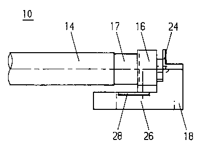
Figure 1 shows a diagrammatic lateral representation of
a connecting accessory 10 for fluorescent lamps. The
connecting accessory 10 comprises in this case two
lampholders 16 constructed separately from one another
and' mutually spaced for holding the corresponding
connecting ends of the fluorescent lamp 14. The
lampholders 16 are each arranged in this case in a
holder receptacle 18 and usually constructed
resiliently. The holder receptacles 18 are mounted on a
corresponding mounting surface 12. It may be seen,
furthermore, that the holder receptacles also each have
a housing cover 20. The housing cover 20 is constructed
in this arrangement in such a way that it covers the
lampholder 16 and a lamp base 17. The housing cover 20
therefore serves additionally to provide shock
protection. Electric connecting lines 22 enter the
holder receptacles 18 at the ends of the holder
receptacle 18 remote from the fluorescent lamp 14. The
electric connecting lines 22 lead in this case to a
ballast (not represented), or come from there.
CA 0224373~ 1998-07-20
97P5556 -7- PATENT APPLICATION
Figure 2 shows a diagrammatically represented side view
of the holder receptacle 18. It may be seen that the
holder receptacle 18 comprises a base element 26 for
holding the device for strain relief 38 (compare
Figures 3 and 4) and a mounting frame 24 for mounting
the lampholder 16. The base element 26 and the mounting
frame 24 are arranged perpendicular to one another in
this case. The base element 26 also has laterally
arranged projections 28 which correspond to
appropriately constructed grooves inside the housing
cover 20 and serve to mount the housing cove~ 20 on the
holder receptacle 18.
Figure 3 shows a longitudinal section through the
holder receptacle 18. It is seen that means 38 for
fixing the electric connecting line 22 in a clamping
fashion are arranged inside the base element 26 (see
also Figure 9). In the exemplary embodiment shown, the
means 38 comprise two mutually spaced strips. The
electric connecting line 22 is guided between said
strips, thus producing a firm seating of electric
connecting line 22 inside the base element 26 by a
corresponding clamping effect. The electric connecting
line 22 is guided in this case through a cutout 36 in
the base element 26 into the latter. After the
connecting line 22 has been appropriately guided
further to the strips, the stripped end of the electric
connecting line 22 lies in a connecting space 42
constructed in the region of the base element 26 (see
also Figure 9). The ends of the electric connecting
line 22 are bent in the direction of the appropriate
connecting points for the purpose of connection to the
actual lampholder 16.
CA 0224373~ 1998-07-20
97P5556 -8- PATENT APPLICATION
Also to be seen are two openings 32, 34 for guiding
through a mounting element (not represented). These
mounting elements are used to mount the connecting
accessory 10 or the individual holder receptacle 18 on
the mounting surface 12.
Figure 4 shows a diagrammatically represented view of
the holder receptacle 18 from below. The position of
the cutouts 36 and 46, which are important for guiding
the electric connecting line 22 inside the base element
26, is to be seen. Also to be seen is that the opening
34 is surrounded by a collar 52. Said collar 52 serves
to deflect the electric connecting line 22 entering the
base element 26 through the cutout 36. At its end
constructed in the region of the mounting frame 24, the
base element 26 has two lateral stops 30 which serve to
stabilize the mounting frame 24. The cutout 40 serves
as an insertion aid for the line 22.
The holder 16 inserted into the mounting frame 24
prevents the connecting line 22 clamped into the strips
from being able to be loosened inadvertently.
Figure 5 shows the holder receptacle 18 with the
housing cover 20 in a diagrammatically represented
front view. In this arrangement, the housing cover 20
surrounds the base element 26 and the mounting frame
24. The lampholder 16 is covered by the housing cover
20.
Figures 6 and 7 show the holder receptacle 18 in a
front view and rear view, respectively. It is to be
seen that the mounting frame 24 has two openings 44 for
holding the mounting element on the lampholder 16.
CA 0224373~ 1998-07-20
97P5556 -9- PATENT APPLICATION
Mounting pins (not represented) of the lampholder 16
are normally guided through said openings 44. It may
also be seen that the mounting frame 24 has two further
openings 46 which serve the purpose of guiding through
electric connecting lines 22. The openings 46 are
arranged in this case in the region of the base element
26 or a base plate 50 (see also Figure 4) of the base
element 26 opposite the cutout 36. This results in a
multiplicity of possible cable runs, the possibilities
for using the connecting accessory 10 thereby being
multiplied in turn. Said possibilities are shown by way
of example in Figures 8a-8c with the aid of
diagrammatically represented side views and bottom
views of three connecting accessories 10 with in each
case a different guidance of the electric connecting
lines 22. A fourth possibility of guidance follows from
Figure 1.