Language selection

Search

Patent 2244178 Summary

Third-party information liability

Some of the information on this Web page has been provided by external sources. The Government of Canada is not responsible for the accuracy, reliability or currency of the information supplied by external sources. Users wishing to rely upon this information should consult directly with the source of the information. Content provided by external sources is not subject to official languages, privacy and accessibility requirements.

Claims and Abstract availability

Any discrepancies in the text and image of the Claims and Abstract are due to differing posting times. Text of the Claims and Abstract are posted:

  • At the time the application is open to public inspection;
  • At the time of issue of the patent (grant).
(12) Patent: (11) CA 2244178
(54) English Title: METHOD OF HEATING A SPECIMEN CARRIER
(54) French Title: METHODE DE CHAUFFAGE POUR PORTE-SPECIMENS
Status: Expired
Bibliographic Data
(51) International Patent Classification (IPC):
  • B01L 7/00 (2006.01)
(72) Inventors :
  • GUNTER, IAN ALAN (United Kingdom)
(73) Owners :
  • BJS COMPANY LTD. (United Kingdom)
(71) Applicants :
  • BJS COMPANY LTD. (United Kingdom)
(74) Agent: NORTON ROSE FULBRIGHT CANADA LLP/S.E.N.C.R.L., S.R.L.
(74) Associate agent:
(45) Issued: 2008-10-14
(86) PCT Filing Date: 1997-01-23
(87) Open to Public Inspection: 1997-07-31
Examination requested: 2002-01-22
Availability of licence: N/A
(25) Language of filing: English

Patent Cooperation Treaty (PCT): Yes
(86) PCT Filing Number: PCT/GB1997/000195
(87) International Publication Number: WO1997/026993
(85) National Entry: 1998-07-24

(30) Application Priority Data:
Application No. Country/Territory Date
9601471.7 United Kingdom 1996-01-25
9603717.1 United Kingdom 1996-02-22

Abstracts

English Abstract


A method and apparatus for heating specimens in wells of a metallic specimen
carrier. The specimen carrier is heated by applying
resistive heating directly to the carrier. An AC source and transformer may be
used where the specimen carrier is in series with a single
turn secondary winding of the transformer.


French Abstract

L'invention porte sur un procédé et un appareil permettant de chauffer des échantillons dans les coupelles d'un porte-échantillons métallique. On chauffe ce dernier directement en faisant directement intervenir une résistance spécifique. On peut utiliser une source de courant alternatif ainsi qu'un transformateur lorsque le porte-échantillon est monté en série, l'enroulement secondaire du transformateur étant à spire unique.

Claims

Note: Claims are shown in the official language in which they were submitted.


CLAIMS:

1. A method of heating a specimen carrier of the kind comprising a plurality
of specimen
sites, which carrier is in the form of a metallic sheet and said sheet is one
of a thin metal
tray coated with a bio-compatible polymer or a metallised plastic tray, the
method
comprising applying a current to said sheet so as to heat specimens carried by
said
carrier.


2. A method according to claim 1 in which the heating is applied as an
alternating current
providing resistive heating, and is controlled to provide repeated cycles of
heating.


3. A method according to any one of claims 1 to 2 in which said metallic sheet
includes a
plurality of wells to contain a plurality of specimens.


4. Apparatus comprising a specimen carrier of the kind carrying a plurality of
specimen
sites, which carrier is in the form of a metallic electrically conductive
sheet, said sheet
being one of a thin metal tray coated with a bio-compatible polymer or a
metallised
plastic tray; power supply means; and a transformer having a primary winding
connected
to said power supply means, and a secondary winding directly connected to said

conductive sheet, thereby providing resistive heating of the sheet to heat the
specimens
carried in the carrier.


5. Apparatus according to claim 4 in which said secondary winding is a single
turn winding.

6. Apparatus according to any one of claims 4 and 5, comprising temperature
control means
connected to regulate flow of heating current through said secondary winding
at a rate
which maintains a controlled heating temperature within said specimen carrier.


7. Apparatus according to claim 6 comprising fan cooling means arranged to
direct cooling
air to a rear side of said specimen carrier and operatively connected to said
temperature
control means.


Description

Note: Descriptions are shown in the official language in which they were submitted.


CA 02244178 2005-01-14
1

METHOD OF HEATING A SPECIMEN CARRIER

The present invention relates to heating and more
particularly to the thermal cycling of specimen carriers.
in many fields specimen carriers in the form of support

blocks or platterns are used for various processes where
small samples are thermally cycled.

A particular example is the Polymerase Chain Reaction
method (often referred to as PCR) for replicating DNA
samples. Such samples require rapid and accurate thermal
cycling, and are typically placed in a multi-well block
and cycled between several selected temperatures in a
pre-set repeated cycle.


Previous methods of heating such specimen carriers have
involved use of resistance wire coiled around the wells,
use of Peltier effect devices or hot air methods.
However such methods are difficult to control to the

precision required, necessitate slow cycle times and can
give rise to thermal over shoot.

The present invention solves this problem by applying
direct electrical resistive heating to a metallic
specimen carrier. Thus the invention provides a method

of heating a specimen carrier in the form of a metallic


CA 02244178 2008-01-17
2

sheet and applying a heating current to said sheet.

In some aspects, there is provided a method of heating a
specimen carrier of the kind comprising a plurality of
specimen sites, which carrier is in the form of a metallic
sheet and said sheet is one of a thin metal tray coated with a
bio-compatible polymer or a metallised plastic tray, the
method comprising applying a current to said sheet so as to
heat specimens carried by said carrier.

In some aspects, there is provided an apparatus comprising a
specimen carrier of the kind carrying a plurality of specimen
sites, which carrier is in the form of a metallic electrically
conductive sheet, said sheet being one of a thin metal tray
coated with a bio-compatible polymer or a metallised plastic
t ray ;
power supply means, and a transformer having aprimary winding
connected to said power supply means, and a secondary winding
directly connected to said conductive sheet, thereby providing
resistive heating of the sheet to heat the specimens carried
in the carrier.

Preferably the metallic sheet will be of silver which has a
high thermal and electrical conductivity. The sheet will
generally have a thin section in the region of 0.3mm
thickness, and may be in a form where a matrix of sample wells
is incorporated in the sheet.

While the metallic sheet may be a solid sheet or block of
silver (which may have cavities forming wells) an alternative
is to use a metallised plastic tray (which may have impressed
wells), in which deposited metal forms a resistive heating
element.


CA 02244178 2008-01-17

2a
Another alternative is to electro form a thin metal tray
(which again may have impressed wells), and to coat the metal
with a bio-compatible polymer.

These measures enable intimate contact to be achieved between
the metallic heating element and the biocompatible sample
receptacles. This gives greatly improved thermal performance
in terms of temperature control and rate of change of
temperature when the actual temperatures of the reagents in
the wells is measured.

The plastic trays are conventionally single use


CA 02244178 1998-07-24

WO 97/26993 PCT/GB97/00195
3
disposable items. The incorporation of the heating
element into the plastic trays may increase their cost,
but the reduction in cycling time for the PCR reaction
more than compensates for any increased cost of the
disposable item.

The bottom of the composite tray should be unobstructed
when fan cooling is employed. If sub-ambient cooling is
required at the end of the PCR cycles, either with a

composite tray or a block, chilled liquid spray-cooling
may be employed. The boiling point of the liquid should
be below the low point of the PCR cycle so that liquid
does not remain on the metal of the tray or block to
impede heating. This also allows for the latent heat of

evaporation of the liquid to increase the cooling effect.
The heating current may be an AC current supplied from
the secondary winding of a transformer. This allows
cycling control to be applied to the primary circuit of

the transformer (higher voltage, lower current) in a
convenient way without encountering problems which arise
when operating with high current devices.

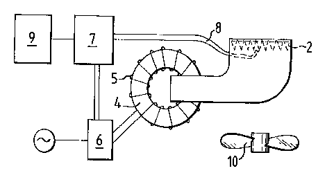
The transformer may comprise a toroidal core having an
appropriate mains primary winding and a single bus bar
looped through the core and connected in series with the


CA 02244178 1998-07-24

WO 97/26993 PCT/GB97/00195
4
metallic sheet to form a single turn secondary circuit.
An embodiment of the invention will now be described by
way of example with reference to the accompanying

diagrammatic drawings in which:

Figure 1 is a side elevation of a heating apparatus, and
Figure 2 is a plan view of the apparatus of Figure 1.

A metallic specimen carrier in the form of a multi-well
block (1) measuring 110mm x 75mm and having 96 wells (2)
disposed in a grid layout is formed in silver nominally
0.3mm thick. This is attached to bus bars (3) of

substantial cross-sectional area. The bus bars loop once
through a transformer (toroidal or square), core (4).
The core (4) has a primary winding (5) appropriate for
the mains voltage employed. The transformer primary
current is controlled using a triac device (6). The

triac device receives current from an AC source and is
controlled by a temperature control circuit (7) which
uses a fine wire thermocouple (8) soldered to a central
underside region of the block to sense the temperature
of the block. The temperature control circuitry may be
operated manually or by a personal computer (9).


CA 02244178 1998-07-24

WO 97/26993 PCT/GB97/00195
Cooling of the block is by means of a fan (10) mounted
under the block, blowing ambient air over the protruding
well forms (2), the air being directed by the enclosure
in which the block is mounted. The fan is controlled by

5 the same temperature control circuitry that drives the
heater triac.

The measured performance of the example apparatus gives
rates of change of temperature in excess of 6 degrees per
second and over/under shoots of less than 0.25 degrees

within the typical PCR working range of 50-100 degrees.
The described examples use a silver block with cavities,
but metalised plastic tray inserts, or electro formed

thin metal trays, as previously described, may also be
used.

The system as described has several important advantages.
1.1 The block is heated directly with no requirement
for heat transfer from an attached heat source. This is

very efficient and taken together with the very low
specific heat capacity of silver allows very rapid
temperature changes.

1.2, Direct heating means that there is no thermal
lag at all. Temperature control functions are immediate


CA 02244178 1998-07-24

WO 97/26993 PCT/GB97/00195
6
so that the block may be cycled in temperature with
little or no over or undershoot. Temperature control is
therefore inherently precise.

1.3 Since there are no obstructions or thermal
barriers attached to the block, simple forced-air cooling
of the back of the block (which may be shaped to increase
its surface area), provides rapid and controllable
cooling.


1.4 The fine wire thermocouple is soldered directly
to the block so as to provide close temperature
measurement and control. Any other temperature
measurement device may be used as long as it does not
introduce significant sensor lag.

1.5 The temperature distribution around the surface
of the block is dependent on the evenness of heating and
the thermal conductivity of the block. The thermal

conductivity of silver is very high, and the distribution
of heat energy around the block is dependent upon the
distribution of the heating current. This may be
regulated by varying the geometry of the multi-well
block.


The large currents required may be easily produced and


CA 02244178 1998-07-24

WO 97/26993 PCT/GB97/00195
7
controlled since the block becomes part of a heavy
secondary circuit of the transformer. The cross-
w
sectional area of the winding bars is made considerably
larger than the cross-sectional area of the block so that
significant heat generation only occurs in the block.

The current can JDe easily controlled in the primary
winding (where the current is small), using thyristors,
triacs or other devices. Alternatively, the primary
winding may be driven by a high frequency, switch mode,

controllable power supply. This allows the same degree
of control of the current induced in the secondary
winding incorporating the block, but the high frequency
allows the use of a more compact core in the transformer,
and reduces inrush current surges when switching the
current on and off.

7

Representative Drawing
A single figure which represents the drawing illustrating the invention.
Administrative Status

For a clearer understanding of the status of the application/patent presented on this page, the site Disclaimer , as well as the definitions for Patent , Administrative Status , Maintenance Fee  and Payment History  should be consulted.

Administrative Status

Title Date
Forecasted Issue Date 2008-10-14
(86) PCT Filing Date 1997-01-23
(87) PCT Publication Date 1997-07-31
(85) National Entry 1998-07-24
Examination Requested 2002-01-22
(45) Issued 2008-10-14
Expired 2017-01-23

Abandonment History

There is no abandonment history.

Payment History

Fee Type Anniversary Year Due Date Amount Paid Paid Date
Registration of a document - section 124 $100.00 1998-07-24
Application Fee $150.00 1998-07-24
Maintenance Fee - Application - New Act 2 1999-01-25 $50.00 1998-07-24
Maintenance Fee - Application - New Act 3 2000-01-24 $50.00 2000-01-20
Maintenance Fee - Application - New Act 4 2001-01-23 $50.00 2001-01-23
Request for Examination $200.00 2002-01-22
Maintenance Fee - Application - New Act 5 2002-01-23 $75.00 2002-01-22
Maintenance Fee - Application - New Act 6 2003-01-23 $75.00 2002-12-30
Maintenance Fee - Application - New Act 7 2004-01-23 $150.00 2003-12-30
Maintenance Fee - Application - New Act 8 2005-01-24 $200.00 2005-01-06
Maintenance Fee - Application - New Act 9 2006-01-23 $200.00 2006-01-13
Maintenance Fee - Application - New Act 10 2007-01-23 $125.00 2007-01-03
Maintenance Fee - Application - New Act 11 2008-01-23 $125.00 2008-01-22
Final Fee $150.00 2008-07-11
Maintenance Fee - Patent - New Act 12 2009-01-23 $125.00 2009-01-12
Maintenance Fee - Patent - New Act 13 2010-01-25 $125.00 2010-01-18
Maintenance Fee - Patent - New Act 14 2011-01-24 $125.00 2011-01-07
Maintenance Fee - Patent - New Act 15 2012-01-23 $225.00 2012-01-19
Maintenance Fee - Patent - New Act 16 2013-01-23 $225.00 2013-01-16
Maintenance Fee - Patent - New Act 17 2014-01-23 $225.00 2014-01-13
Maintenance Fee - Patent - New Act 18 2015-01-23 $225.00 2015-01-21
Maintenance Fee - Patent - New Act 19 2016-01-25 $225.00 2016-01-21
Owners on Record

Note: Records showing the ownership history in alphabetical order.

Current Owners on Record
BJS COMPANY LTD.
Past Owners on Record
GUNTER, IAN ALAN
Past Owners that do not appear in the "Owners on Record" listing will appear in other documentation within the application.
Documents

To view selected files, please enter reCAPTCHA code :


To view images, click a link in the Document Description column. To download the documents, select one or more checkboxes in the first column and then click the "Download Selected in PDF format (Zip Archive)" or the "Download Selected as Single PDF" button.

List of published and non-published patent-specific documents on the CPD .

If you have any difficulty accessing content, you can call the Client Service Centre at 1-866-997-1936 or send them an e-mail at CIPO Client Service Centre.


Document
Description 
Date
(yyyy-mm-dd) 
Number of pages   Size of Image (KB) 
Representative Drawing 2008-09-29 1 7
Abstract 1998-07-24 1 46
Description 1998-07-24 7 205
Claims 1998-07-24 3 62
Representative Drawing 1998-11-13 1 7
Drawings 1998-07-24 1 15
Cover Page 1998-11-13 1 32
Claims 2008-01-17 1 40
Description 2008-01-17 8 226
Description 2005-01-14 7 202
Claims 2005-01-14 2 59
Claims 2005-09-09 2 60
Claims 2006-03-28 2 60
Claims 2006-10-23 2 70
Cover Page 2008-09-25 1 33
Correspondence 2007-07-31 1 39
Prosecution-Amendment 2006-06-15 3 124
Prosecution-Amendment 2008-01-17 8 310
Correspondence 1998-11-06 2 74
PCT 1998-07-24 10 297
Assignment 1998-07-24 6 196
Prosecution-Amendment 2002-01-22 2 52
Prosecution-Amendment 2003-08-25 1 37
Prosecution-Amendment 2005-01-14 6 183
Prosecution-Amendment 2004-09-08 2 56
Prosecution-Amendment 2005-03-09 2 67
Prosecution-Amendment 2005-09-09 3 103
Prosecution-Amendment 2005-10-06 2 73
Prosecution-Amendment 2006-03-28 4 133
Prosecution-Amendment 2006-10-23 4 163
Correspondence 2007-01-19 2 81
Prosecution-Amendment 2007-07-23 3 101
Correspondence 2007-10-10 2 47
Correspondence 2008-07-11 3 111
Correspondence 2009-01-12 1 47
Correspondence 2009-01-12 1 45
Correspondence 2010-01-18 2 86
Correspondence 2011-01-07 1 46