Note: Descriptions are shown in the official language in which they were submitted.
' ~ CA 02244317 1998-07-29
TITLE
APPARATUS FOR PERFORMING A HYDROFORMING OPERATION
s BACKGROUND OF THE INVENTION
This invention relates in general to an apparatus for performing a hydroforming
operation on a closed channel workpiece. In particular, this invention relates to an
irnproved structure for such a hydroforming apparatus that is relative simple and
inexpensive in structure and operation and is well suited for performing a
o hydroforming operation on relatively long workpieces, such as side rails for a véhicle
frame assembly.
Hydroforming is a well known metal working process that uses pressurized
fluid to expand a closed channel workpiece, such as a tubular member, outwardly into
conformance with a die cavity having a desired shape. A typical hydroforming
apparatus includes a frame having a two or more die sections that are supported
thereon for relative movement between opened and closed positions. The die sections
have cooperating recesses formed therein which together define a die cavity having a
shape corresponding to a desired final shape for the workpiece. When moved to the
opened position, the die sections are spaced apart from one another to allow a
workpiece to be inserted within or removed from the die cavity. When moved to the
closed position, the die sections are disposed adjacent to one another so as to enclose
the workpiece within the die cavity. Although the die cavity is usually somewhatlarger than the workpiece to be hydroformed, movement of the two die sections from
the opened position to the closed position may, in some instances, cause some
mechanical deformation of the hollow member. In any event, the workpiece is thenfilled with a fluid, typically a relatively incompressible liquid such as water. The
pressure of the fluid within the workpiece is increased to such a magnitude that the
workpiece is expanded outwardly into conformance with the die cavity. As a result,
the workpiece is deformed into the desired final shape. Hydroforming is an
' ' CA 02244317 1998-07-29
advantageous process for forming vehicle frame components and other structures
because it can quickly deform a workpiece into a desired complex shape.
In a typical hydroforming apl)ar~ s, the die sections are arranged such that an
upper die section is supported on a ram of the al)pa,alus, while a lower die section is
s supported on a bed of the apparatus. A mechanical or hydraulic actuator is provided
for raising the ram and the upper die section upwardly to the opened position relative
to the lower die section, allowing the previously deformed workpiece to be removed
from and the new workpiece to be inserted within the die cavity. The actuator also
lowers the ram and the upper die section downwardly to the closed position relative to
o the lower die section, allowing the hydroforming process to be performed. To
m~int?~in the die sections together during the hydroforming process, a mechanical
clamping device is usually provided. The mechanical clamping device mechanicallyengages the die sections (or, alternatively, the ram and the base upon which the die
sections are supported) to prevent them from moving apart from one another during
lS the hydroforming process. Such movement would obviously be undesirable because
the shape of the die cavity would become distorted, resulting in unacceptable
variations in the final shape of the workpiece.
As mentioned above, the hydroforming process involves the application of a
highly pressurized fluid within the workpiece to cause expansion thereof. The
20 m~nihl~e of the pressure of the fluid within the workpiece will vary according to
many factors, one of which being the physical size of the workpiece to be deformed.
When a relatively small or ~in-walled workpiece is being deformed, the magnitude of
the pressure of the fluid supplied within the workpiece during the hydroforming
operation is relatively small. Accordingly, the amount of the outwardly-directed force
2s exerted by the workpiece on the die sections during the hydroforming operation is also
relatively small. In these instances, only a relatively small amount of inwardly-
directed force is required to be exerted by the hydroforming apparatus to counteract
the outwardly-directed force so as to m~int~in the die sections in the closed position
during the hydroforming operation. Consequently, the physical size and strength of
30 the hydroforming apparatus when used for deforming relatively small or ~in-walled
,. .. . ... . . , ~, .. . . . . . . . .. .. .. . . .. . . .
' CA 02244317 1998-07-29
workpieces is no greater than a typical mechanical press for perforrning a similar
operation.
However, when a relatively large or thick-walled workpiece is being deforrned
(such as is found in many vehicle frame components, including side rails, cross
s members, and the like), the magnitude of the pressure of the fluid supplied within the
workpiece during the hydroforrning operation is relatively large. Accordingly, the
amount of the outwardly-directed force exerted by the workpiece on the die sections
during the hydroforming operation is also relatively large. To counteract this, a
relatively large amount of inwardly-directed force is required to be exerted by the
10 hydroforming apparatus to m~int~in the die sections in the closed position during the
hydroforn~ing operation. Consequently, the physical size and strength of the
hydroforming apparatus is as large or larger than a typical mechanical press forperforming a similar operation. This is particularly troublesome when the workpiece
is relatively long, such as found in side rails for vehicle frames. The cost and5 complexity of manufacturing a conventional hydroforming apparatus which is capable
of deforming such a workpiece is very high. Thus, it would be desirable to provide an
improved structure for a hydroforming apparatus which is capable of deforming
relatively large and thick-walled workpieces, yet which is relatively small, simple, and
inexpensive in construction and operation.
SUMMARY OF THE INVENTION
This invention relates to an improved structure for a hydrofoIming apparatus
which is capable of deforming relatively large and thick-walled workpieces, yet which
is relatively small, simple, and inexpensive in construction and operation. The
25 hydroforming apparatus includes a pressure vessel that is disposed within a frame.
The pressure vessel includes upper and lower vessel members that support respective
die sections therein. When the upper and lower vessel members are moved adjacent to
one another, the die sections cooperate to define a die cavity in which a workpiece to
be hydroformed is disposed. An infl~t~ble bladder is disposed between one or both of
30 the die sections and the associated upper and lower vessel members. Du~ng the
' CA 02244317 1998-07-29
hydroforming operation, pressurized fluid is introduced within the workpiece so as to
expand it outwardly into conformance with the die cavity defined by the die sections.
At the same time, pressurized fluid is introduced into the infl~t~ble bladder, c~llsing it
to expand between the die sections and the associated upper and lower vessel
members. The infl~t~ble bladder allows for limited expansion of the upper and lower
vessel members while preventing relative movement between the die sections. As aresult, the size, complexity, and cost of the hydroforming apparatus can be m~int~ined
at a minimllm while facilitating the hydroforming of relatively large and thick-walled
workpieces, such as vehicle frame components.
Vuious objects and advantages of this invention will become apparent to those
skilled in the art from the following detailed description of the ~lef~.led embo~limerlt
when read in light of the accompanying drawings.
BRIEF DESCRIPTION OF THE DRAWINGS
Fig. 1 is a perspective view of a hydroforming apparatus in accordance with
this invention.
Fig. 2 is an end elevational view, partially in cross section, of the hydroforming
apparatus illustrated in Fig. 1.
Fig. 3 is an enlarged view of a portion of the hydroforming apparatus illustrated
in Fig. 2.
Fig. 4 is a top plan view of the pressure vessel of the hydroforming ap~aralus
illustrated in Fig. 1.
DETAILED DESCRIPTION OF THE PREFERRED EMBODIMENTS
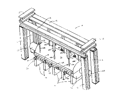
2s Referring now to the drawings, there is illustrated in Figs. 1 through 4 a first
embodiment of a hydroforming apparatus, indicated generally at 10, in accordancewith this invention. The hydroforming apparatus 10 includes a frame that, in theillustrated embodiment, consists of four uprights 11, a pair of longitll~lin~lly extending
side bearns 12, and a pair of transversely extending cross beams 13. The illustrated
uprights 11, side beams 12, and cross beams 13 are embodied as conventional I-beams
' CA 02244317 1998-07-29
(although such is not necessary) and are arranged in the shape of a rectangular
parallelepiped. However, it will be appreciated that the frame of the hydroforrning
apparatus 10 may be constructed in any other conventional manner.
The hydroforming apparatus 10 also includes a pressure vessel, indicated
5 generally at 20, which is disposed within the frame. The pressure vessel 20 isgenerally cylindrical in shape and extends throughout most of the longitll-lin~l length
of the frame 10. A plurality of spaced apart supports 21 are provided for supporting
the pressure vessel 20 on a support surface. As best shown in Figs. 2 and 3, each of
the supports 21 has a semi-circular recess 2 la formed in the upper surface thereof for
o receiving the lower portion of the pressure vessel 20 therein. Although not shown, the
supports 21 may be integrated with the frame 10 into a single unit. Regardless, the
pressure vessel 20 may be supported relative to the frame 10 in any conventionalmanner.
The hydroforming apparatus 10 fur~er includes a pair of end feed cylinders 22
that are located at the opposite ends of the pressure vessel 20. The end feed cylinders
22 are conventional in the art and are adapted to engage the ends of a workpiece (not
shown) disposed wi~in a die cavity defined within the pressure vessel 20 to perform a
hydroforming operation. As is well known, the end feed cylinders 22 are adapted to
fill the workpiece with a fluid, typically a relatively incompressible liquid such as
20 water, from a source of pressurized fluid (not shown). The pressure of the fluid within
the workpiece is then increased to such a magnitude that the workpiece is expanded
outwardly into conformance with the die cavity. Thus, the die cavity is preferably
shaped to have a desired final shape for the workpiece.
Referring now to Figs. 2 and 3, the structure of the pressure vessel 20 is
25 illustrated in detail. As shown therein, the pressure vessel 20 includes an upper vessel
member 30 and a lower vessel member 40, both of which are generally semi-
cylindrical in shape. The vessel members 30 and 40 are preferably formed from a
strong, rigid material, such as steel. The illustrated vessel members 30 and 40 extend
longitudinally throughout the entire length of the pressure vessel 20. However, each
30 of the vessel members 30 and 40 may be divided into a plurality of shorter length
CA 02244317 1998-07-29
segments that are secured together in a conventional marmer. By forrning the vessel
members 30 and 40 in such shorter lengths, the overall size of the pressure vessel 20
may be adjusted to accommodate workpieces of varying length.
The upper vessel member 30 has a central recess 31 formed therein that extends
s longit~l~1in~11y throughout the length thereof. The upper vessel member 30 also has a
pair of relatively narrow slots 32 formed near the sides thereof, preferably on opposite
sides of the central recess 31. The slots 32 extend longitll-lin~lly throughout the length
of the upper vessel member 30 and are provided for a purpose that will be explained in
detail below. A plurality of transversely extending counterbores 33 are forrned in the
o upper vessel member 30, extending inwardly from each of the sides of the uppervessel member 30. As best shown in Fig. 4, fifteen equidistantly spaced counterbores
33 are formed in each side of the upper vessel member 30. However, it will be
appreciated that the number and location of such counterbores 33 may be varied as
desired. Each of the counterbores 33 intersects and extends through the slots 32S formed ~rough the upper vessel member 30. The purpose of the counterbores 33 will
also be explained in detail below.
An upper tool holder 35 is disposed within the central recess 31 foImed in the
upper vessel member 30. The upper tool holder 35 has an outer surface ~at conforms
generally in shape to the inner surface of the central recess 31 of the upper vessel
20 member 30. Thus, the upper tool holder 35 may be secured to the upper vessel
member 30 in any conventional manner, such as by a plurality of threaded fasteners
(not shown). The upper tool holder 35 is formed having a generally U-shaped cross
section, defining a recessed area 36. The illustrated upper tool holder 35 extends
longitudinally throughout the leng~ of the upper vessel member 30. However, as with
2s the upper vessel member 30, the upper tool holder 35 may be divided into a plurality
of shorter length segrnents that are secured together in a conventional manner. An
upper die section or tool insert 37 is disposed within the recessed area 36 forrned in
the upper tool holder 35. The upper die section 37 has an outer surface that conforms
generally in shape to the inner surface of the recessed area 36 of the upper tool holder
30 35. Thus, the upper die section 37 may be secured to the upper tool holder 35 in any
CA 02244317 1998-07-29
conventional manner, such as by a plurality of threaded fasteners (not shown). The
upper die section 37 has a cavity portion 38 formed in the lower surface thereof for a
purpose that will be explained in detail below. The upper tool holder 35 and the upper
die section 37 are preferably formed from a strong, rigid material, such as steel.
The lower vessel member 40 has a central recess 41 formed therein that extends
longit~ in~lly throughout the length thereo~ As best shown in Fig.3, the centralrecess 41 has a pair of inwardly extending shoulders 41a formed on the sides thereof,
extentlin~g longit~din~lly throughout the length thereof. The purpose of the shoulders
4 la will be explained in detail below. The lower vessel member 40 also has a pair of
o relatively narrow slots 42 formed near the sides thereof, preferably on opposite sides
ofthe central recess 41. The slots 42 extend longitll~lin~lly throughout the length of
the lower vessel member 40 and are provided for a purpose that will be explained in
detail below. A plurality of trarlsversely exten~ing counterbores 43 are formed in the
lower vessel member 40, extending inwardly from each of the sides of the lower
vessel member 40. Similar to the upper vessel member 30 described above, fifteenequidistantly spaced counterbores 43 are formed in each side of the lower vesselmember 40. However, it will be appreciated that the number and location of such
counterbores 43 may be varied as desired. Each of the counterbores 43 intersects and
extends ~rough the slots 42 formed through the lower vessel member 40. The
20 purpose of the counterbores 43 will also be explained in detail below.
A lower tool holder 45 is disposed within the central recess 41 formed in the
lower vessel member 40. The lower tool holder 45 has an outer surface that conforms
generally in shape to the inner surface of the central recess 41 of the lower vessel
member 40. However, as best shown in Fig.3, the lower tool holder 45 has a pair of
2~ outwardly extending shoulders 45a forrned on the sides thereof, extending
longitll(lin~lly throughout the length thereof. The outwardly extending shoulders 45a
of the lower tool holder 45 cooperate with the inwardly extending shoulders 4 laformed in the central recess 41 of the lower vessel member 40 to support the lower
tool holder 45 on the lower vessel member 40. When so supported, a relatively small,
30 longitudinally extending space is defined between the lower surface of the lower tool
CA 02244317 1998-07-29
holder 45 and the upper surface of the central recess 41 formed in the lower vessel
member 40. The purpose of this longihl-linally extending space will be explained in
detail below.
The lower tool holder 45 is formed having a generally U-shaped cross section,
s defining a recessed area 46. The illustrated lower tool holder 45 extends
longit~lclin~lly throughout the length of the lower vessel member 40. However, as with
the lower vessel member 40, the lower tool holder 45 may be divided into a plurality
of shorter length segments that are secured together in a conventional manner. An
lower die section or tool insert 47 is disposed within the recessed area 46 formed in
o the lower tool holder 45. The lower die section 47 has an outer surface that conforms
generally in shape to the inner surface of the recessed area 46 of the lower tool holder
40. Thus, the lower die section 47 may simply rest within the lower tool holder 45 or
be secured to the lower tool holder 45 in any conventional manner, such as by a
plurality of threaded fasteners (not shown). The lower die section 47 has a cavity
5 portion 48 formed in the upper surface thereof for a purpose that will be explained in
detail below. The lower tool holder 45 and the lower die section 47 are preferably
formed from a strong, rigid material, such as steel.
When the upper vessel member 30 is located adjacent to the lower vessel
member 40 as illustrated in Figs. 2 and 3, the cavity portions 38 and 48 of the upper
20 and lower die sections 37 and 47, respectively, cooperate to define a die cavity. A
represent~hve shape for a die cavity adapted to hydroform an elongated vehicle side
rail is shown in Fig. 4. As is well known in the a~t, the die cavity defines a desired
shape for a workpiece to be deformed by hydroforming. As mentioned above,
hydroforming is a well known metal working process that uses pressurized fluid to '
25 expand a closed channel workpiece, such as a tubular member, outwardly into
conformance with the die cavity. Thus, in order to perform a hydroforming operation,
the upper vessel member 30 must be moved adjacent to the lower vessel member 40 as
illustrated. The upper vessel member 30 is raised above the lower vessel member 40
to allow a workpiece to be inserted within or removed from the die cavity. Although
30 the die cavity is usually somewhat larger than the workpiece to be hydroformed,
~ CA 02244317 1998-07-29
movement of the upper vessel member 30 to the position illustrated in Figs. 2 and 3
may, in some instanccs, cause some mechanical deformation of the workpiece.
As mentioned above, the lower tool holder 45 is supported on the lower vessel
member 40 in such a m~nner as to provide a relatively small, longitudin~lly extending
s space between the lower surface of the lower tool holder 45 and the upper surface of
the central recess 41 formed in the lower vessel member 40. An infl~t~ble bladder 49
is disposed within this lon,Qit~ldin~lly extending space. The illustrated bladder 49 is
formed from a fluid-tight flexible material, such as rubber or other elastomericmaterial. However, as will be explained in detail below, the bladder 49 may be
o formed in any shape and from any material so as to be capable of physical expansion
in response to the application of pressurized fluid therein. The purpose for the bladder
49 will be explained in detail below.
The pressure vessel 20 includes a locking structure for selectively securing theupper vessel member 30 to the lower vessel member 40 to permit a hydroforming
operation to be performed. The illustrated locking structure includes a pair of locking
bars 50. As best shown in Fig. 3, the upper portions of the locking bars 50 are
disposed within the slots 32 forrned in the upper vessel member 30, while the lower
portions of the locking bars 50 are disposed within the slots 42 formed in the lower
vessel member 40. Each of the locking bars 50 extends longitu~in~lly throughout the
20 lengths of the upper and lower vessel members 30 and 40, as shown in Fig. 4. An
upper plurality of apertures 51 is forrned through the upper portions of each of the
locking bars 50. The upper apertures 51 correspond in size, shape, and location to the
counterbores 33 formed in the upper vessel member 30. Similarly, a lower plurality of
ape~ es.52 is formed through the lower portions of each of the locking bars 50. The
25 lower apertures 52 correspond in size, shape, and location to the counterbores 43
formed in the lower vessel member 40.
The locking structure also includes a mech~ni~m for securing the lower
portions of the locking bars 50 to the lower vessel member 40. In the illustrated
embodiment, this mech~nism includes a plurality of fixed pins 53 that are disposed
30 within each of the counterbores 43 forrned in the lower vessel member 40. As
CA 02244317 1998-07-29
mentioned above, each of the counterbores 43 intersects and extends through the slots
42 formed through the lower vessel member 40. Thus, as shown in Figs. 3 and 4, the
fixed pins 53 extend through both the counterbores 43 and the lower apertures 52formed through the locking bars 50. In this m~nner, the lower portions of the locking
s bars S0 are securely fastened to the lower vessel member 40. In the illustrated
embodiment, the fixed pins 53 are not intended to be readily removable from the
lower vessel member 40. Thus, the fixed pins 53 can be press fit or otherwise retained
within the counterbores 43. However, it will be appreciated that the fixed pins 53 can
be altered to facilitate the removal thereof if desired. Notwithstanding the above, it
lO will be appreciated that any other conventional structure may be used to retain the
locking bars 50 on the lower vessel member 40.
The locking structure further includes a mechanism for releasably securing the
upper portions of the locking bars 50 to the upper vessel member 30. In the illustrated
embo~iment this mech~ni~m includes a plurality of movable pins 54 that are disposed
15 within each of the counterbores 33 formed in the upper vessel member 30. As
mentioned above, each of the counterbores 33 intersects and extends through the slots
32 formed through the upper vessel member 30. Thus, as shown in Figs. 3 and 4, the
movable pins 54 extcnd through both the coullte.bores 33 and the upper apertures 51
formed through the locking bars 50. In ~is m~nner, the upper portions of the locking
20 bars S0 can be securely fastened to the upper vessel member 30. In the illustrated
emboclimerlt, the movable pins 54 are intended to be readily removable from the upper
vessel member 30. To accomplish this, the movable pins 54 are secured to a pair of
header bars 55 that extend longitudinally along the opposed sides of the pressure
vessel 20. Thus, when the header bars 55 are moved outwardly away from the sides25 of the pressure vessel 20, the movable pins 54 are moved out of the upper apertures 51
formed through the locking bars S0. In this manner, ~e upper vessel member 30 can
be released from the locking bars 50 and, consequently, the lower vessel member 40.
The movable pins 54 are shown in Figs. 3 and 4 as being formed integrally with the
header bars 55. However, the movable pins 54 may be forrned separately from the
30 header bars 55 or, alternatively, may be formed as independently movable members
CA 02244317 1998-07-29
that can be individually moved into and out of engagement with the locking bars 50.
Notwithstanding the above, it will be appreciated that any other conventional structure
may be used to retain the locking bars 50 on the lower vessel member 40.
In the illustrated embodiment, a plurality of slides 56 are provided for
5 supporting the header bars 55 (and, thus, the movable pins 54) for sliding movement
between a locked position, wherein the upper vessel member 30 is secured to the
lower vessel member 40, and an unlocked position, wherein the upper vessel member
30 is secured to the lower vessel member 40. As best shown in Fig. 4, each of the
slides 56 includes a shaft portion that is secured to the outer surface of the upper
o vessel member 30 and extends through respective slide apertures 56a formed through
the header bars 55. Each of the slides 56 further includes an enlarged head portion
which limits the outward movement of the header bars 55 away from the opposed
sides of the pressure vessel 20. The slides 56 are designed to support the weight of the
header bars 55 on the upper vessel member 30 so as to allow free sliding movement
thereof. It will be appreciated, however, that any other conventional structure may be
provided for supporting the header bars 55 for sliding movement between the locked
and unlocked positions.
In the illustrated embodiment, a plurality of hydraulic cylinders 57 is providedto effect movement of the header bars 55 (and, thus, the movable pins 54) between the
20 locked position and the ~mlocked position. The body portions of the hydrauiiccylinders 57 are mounted on respective fixed supports illustrated in dotted lines at 57a
in Fig. 3. Movable rod portions 57b extend outwardly from the body portions and are
secured to the header bars 55. The hydraulic cylinders 57 are connected through
conventional valves (not shown) to a source of pressurized fluid. In a manner that is
25 well known in the art, the valves can be actuated so as to cause the rod portions 57b to
be extended from the hydraulic cylinders 57, thereby moving the header bars 55 and
the movable pins 54 inwardly to the locked position illustrated in Figs. 2, 3, and 4.
Similarly, the valves can be actuated so as to cause the rod portions 57b to be retracted
within the hydraulic cylinders 57, thereby moving the header bars 55 and the movable
30 pins 54 outwardly to the unlocked position. Preferably, the valves are actuated by
CA 02244317 1998-07-29
solenoids, and an electronic control circuit is provided to effect the operation of the
hydraulic cylinders 57. However, it will be appreciated that any conventional
structure may be provided to effect movement of the header bars 55 and the movable
pins 54 between the locked position and the unlocked position.
s The hydroforming apparatus 10 further includes a mech~ni.~m for selectively
raising and lowering the upper vessel member 30 relative to the lower vessel member
40. In the illustrated embodiment, this raising and lowering mechanism includes a
plurality of hydraulic cylinders 60. As best shown in Fig. 2, the body portions of the
hydraulic cylinders 60 are secured to the lower surfaces of the lon~ lin~lly
o extending side beams 12, extending downwardly therefrom. Movable rod portions60a of the hydraulic cylinders 60 extend outwardly from the body portions and are
secured to the upper vessel member 30 in any conventional manner. The hydraulic
cylinders 60 are connected through conventional valves (not shown) to a source of
pressurized fluid. In a manner that is well known in the art, the valves can be actuated
so as to cause ~e rod portions 60a to be extended from the hydraulic cylinders 60,
thereby lowering the upper vessel member 30 downwardly into engagement with the
lower vessel member 40, as shown in Figs. 1, 2, and 3. Similarly, the valves can be
actuated so as to cause the rod portions 60a to be retracted within the hydraulic
cylinders 60, thereby raising the upper vessel member 30 above the lower vessel
20 member 40. Preferably, the valves are actuated by solenoids, and an electronic control
circuit is provided to effect the operation of the hydraulic cylinders 60. However, it
will be appreciated that any conventional structure may be provided to effect
movement of the upper vessel member 30 relative to the lower vessel member 40.
The operation of the hydroforming apparatus 10 will now be described.
25 Initially, the hydraulic cylinders 60 are actuated to raise the upper vessel member 30
relative to the lower vessel member 40. As discussed above, the raising of the upper
vessel member 30 allows a workpiece to be disposed within cavity portion 48 formed
in the upper surface of the lower die section 47. As is known in the art, the workpiece
may be prelimin~rily deformed in a conventional tube bending apparatus so as to
30 possess ~e general shape of the die cavity. In any event, the hydraulic cylinders 60
CA 02244317 1998-07-29
are then actuated to lower the upper vessel member 30 into abutment with the lower
vessel member 40, as shown in Figs. 2 and 3. Although the die cavity defined by the
upper die section 37 and the lower die section 47 is usually somewhat larger than the
workpiece to be hydroformed, movement of the two die sections 37 and 47 from thes opened position to the closed position may, in some instances, cause some mechanical
deformation of the workpiece.
In any event, once the upper vessel member 30 is disposed adjacent to the
lower vessel member 40, the locking mech~ni~m is actuated to securely fasten theupper vessel member 30 to the lower vessel member 40. This is accomplished by
o actll~tine ~e hydraulic cylinders 60 to move the header bars 55 from the unlocked
position to the locked position. As discussed above, such movement of the headerbars 55 causes the movable pins 54 to extend into the counterbores 33 formed in the
upper vessel member 30 and the upper apertures 51 formed through the locking bars
50. As a result, the upper vessel member 30 is securely fastened to the lower vessel
5 member 40.
Next, the end feed cylinders 22 are then actuated to engage the ends of the
workpiece and fill the workpiece with a relatively incompressible liquid, such as
water. The pressure of the fluid within the workpiece is increased by a conventional
intencifier or other conventional portion of the source of pressurized fluid to such a
20 m~nit~lde that the workpiece is expanded outwardly into conformance with the die
cavity defined by the cooperating cavity portions 38 and 48. As a result, the
workpiece is deformed into the desired final shape.
Because the hydroforming process involves ~e application of a highly
pressurized fluid within the workpiece to cause expansion thereof, the workpiece25 exerts an outwardly directed force against the die sections 37 and 47 during the
hydroforming operation. This outwardly directed force is, in turn, applied through the
upper and lower tool holders 35 and 45 to the upper and lower vessel members 30 and
40. The magnitude of this force will vary according to many factors, one of which
being the physical size of the workpiece to be deformed. When a relatively large or
30 thick-walled workpiece is being deformed (such as is the case when hydrofo~ning
CA 02244317 1998-07-29
many vehicle frame components), the magnitude of this force is relatively large. As a
result, portions of the upper and lower vessel members 30 and 40 may be deflected
outwardly under the influence of this force. Such deflections would obviously beundesirable because they might allow relative movement to occur between the
s cooperating upper and lower die sections 37 and 47, respectively. As discussedabove, the conventional approach to preventing such deflections is to increase the
physical size of the hydroforming machine, with the attendant increased cost andcomplexity.
The hydroforming apparatus 10 of this invention does not prevent such
o deflections from occurring in the upper and lower vessel members 30 and 40. Rather,
the hydroforming apparatus 10 of this invention relies upon the infl~t~ble bladder 49
to generate an inwardly directed force ~inct the upper and lower die sections 37 and
47, respectively, to n~int~in them in position during the hydroforming operation. To
accomplish this, the infl~table bladder 49 is pressurized prior to and/or during the
hydroforming operation. As discussed above, the infl~t~ble bladder 49 is designed to
be capable of physical expansion in response to the application of pressurized fluid
therein. The infl~t~ble bladder 49 may be connected to the same source of pressurized
fluid as the end feed cylinders 22 such that the sarne pressurized fluid that is supplied
to the interior of ~e workpiece is also supplied within the infl~t~ble bladder 49.
20 Alternatively, pressurized fluid may be supplied within the infl~t~ble bladder 49 from
an independent source. The supply of such pressurized fluid within the infl~t~ble
bladder 49 may be controlled by conventional valves (not shown), and the operation of
such valves may be controlled by a conventional control system (not shown),
including the electronic control circuit provided for automatically operating the
25 hydroforrning apparatus 10 as described above.
In any event, the application of pressurized fluid within the infl~t~ble bladder49 causes physical expansion thereof. As a result of such physical expansion, the
inflated bladder 49 reacts between the lower tool holder 45 and the lower vesselmember 40, exerting a force to urge them apart from one another. The magnitude of
30 ~is force is preferably selected to be approximately equal to the ma~nitude of the
14
_ CA 02244317 1998-07-29
,
outwardly directed force exerted by the workpiece against the lower die section 47
and, thus, the lower tool holder 45. So long as the outwardly directed force generated
by expansion of the workpiece is approxim~tely equal to the inwardly directed force
generated by ~e expansion of the inflated bladder 49, the effective force exerted
s ~g~inst the lower die section 47 tending to move it relative to the upper die section 37
will be rninimi7ed As a result, the lower die section 47 will remain in positionrelative to the upper die section 37 during ~e hydroforming operation, even though
portions of the upper and lower vessel members 30 and 40 may be deflected. In
effect, the infl~t~ble bladder 49 pre-stresses the upper and lower vessel members 30
o and 40 and fills any extra space created by the deflections of portions of such véssel
members 30 and 40, thereby retaining the die sections 37 and 47 in position during the
hydroforming operation.
In accordance with the provisions of the patent statutes, the principle and modeof operation of this invention have been explained and illustrated in its preferred
embo~liment However, it must be understood that this invention may be practiced
otherwise than as specifically explained and illustrated without departing from its
spirit or scope.