Language selection

Search

Patent 2244511 Summary

Third-party information liability

Some of the information on this Web page has been provided by external sources. The Government of Canada is not responsible for the accuracy, reliability or currency of the information supplied by external sources. Users wishing to rely upon this information should consult directly with the source of the information. Content provided by external sources is not subject to official languages, privacy and accessibility requirements.

Claims and Abstract availability

Any discrepancies in the text and image of the Claims and Abstract are due to differing posting times. Text of the Claims and Abstract are posted:

  • At the time the application is open to public inspection;
  • At the time of issue of the patent (grant).
(12) Patent: (11) CA 2244511
(54) English Title: METHOD OF MAKING INJECTION MOLDING COOLED THREAD SPLIT INSERTS
(54) French Title: METHODE DE FABRICATION DE DOUILLES DIVISEES FILETEES ET REFROIDIES POUR LE MOULAGE PAR INJECTION
Status: Deemed expired
Bibliographic Data
(51) International Patent Classification (IPC):
  • B29C 45/73 (2006.01)
  • B23P 15/00 (2006.01)
  • B23P 15/24 (2006.01)
  • B29C 33/04 (2006.01)
  • B29C 33/38 (2006.01)
(72) Inventors :
  • GELLERT, JOBST ULRICH (Canada)
(73) Owners :
  • MOLD-MASTERS (2007) LIMITED (Canada)
(71) Applicants :
  • GELLERT, JOBST ULRICH (Canada)
(74) Agent: RIDOUT & MAYBEE LLP
(74) Associate agent:
(45) Issued: 2008-12-23
(22) Filed Date: 1998-07-29
(41) Open to Public Inspection: 2000-01-29
Examination requested: 2003-07-21
Availability of licence: N/A
(25) Language of filing: English

Patent Cooperation Treaty (PCT): No

(30) Application Priority Data: None

Abstracts

English Abstract

A method of making pairs of thread splits inserts used to injection mold bottle preforms. Machining a hollow outer part of the pair of thread split inserts with an opening therethrough and outer portions of two cooling conduits extending from the opening therethrough to respective inlets and outlets. Making an inner part of the pair of thread split inserts by injection molding a ceramic core with the required shape and investment casting the inner part around the ceramic core. The outer surface of the inner part having grooves to partially form inner portions of the two cooling fluid conduits. Then machining the cast inner part to fit in the opening through the outer part. Mounting the outer part around the inner part with the inner and outer portions of the two cooling fluid conduits aligned. Applying brazing material between the inner and outer parts and heating them in a vacuum furnace to integrally braze them together. Finally, cutting the integral inner and outer parts in half to form the pair of thread split inserts with each of the thread split inserts having one of the cooling fluid conduits therein.


French Abstract

Une méthode de fabrication de paires de pièces rapportées divisées et filetées utilisées pour des préformes de bouteille à moulage par injection. L'usinage d'une partie extérieure creuse de la paire de pièces rapportées divisées et filetées avec une ouverture les traversant et de parties extérieures de deux conduites de refroidissement se prolongeant à partir de l'ouverture vers des entrées et des sorties respectives. La fabrication d'une partie intérieure de la paire de pièces rapportées divisées et filetées par le moulage par injection d'un noyau en céramique avec la forme requise et le moulage par enrobage de la partie intérieure autour du noyau en céramique. La surface extérieure de la partie intérieure étant munie de rainures pour former partiellement des parties intérieures de deux conduites de fluide de refroidissement. Ensuite, l'usinage de la partie intérieure du moule pour s'ajuster dans l'ouverture traversant la partie extérieure. Le montage de la partie extérieure autour de la partie intérieure avec les parties intérieure et extérieure des deux conduites de fluide de refroidissement alignées. L'application de métal d'apport de brasage fort entre les parties intérieure et extérieure et les faisant chauffer dans un four à vide pour les braser ensemble intégralement. Enfin, la découpe en moitié des parties intérieure et extérieure intégrales pour former la paire de pièces rapportées divisées et filetées avec chaque pièce rapportée divisée et filetée munie d'une conduite de fluide de refroidissement.

Claims

Note: Claims are shown in the official language in which they were submitted.


15

CLAIMS

1. A method of making a pair of split inserts used in injection molding
elongated
hollow preforms, each preform having a neck portion with an outer surface,
each split
insert having first and second inner aligned faces extending on opposite sides
of a
curved inner surface, the split inserts to be mounted together in a mold with
the
respective inner faces of the split inserts abutting, wherein the curved inner
surfaces of
the split inserts combine to form an opening therethrough shaped to mold the
outer
surface of the neck portion of the preform, comprising the steps of:

(a) casting a suitable metal in a mold to form a hollow inner part of the pair
of
split inserts extending around a central longitudinal axis, said inner part
having outer surface with grooves therein to partially form inner portions of
two cooling fluid conduits, each cooling fluid conduit to extend around the
curved inner surface of one of the split inserts,

(b) making a hollow outer part of the pair of split inserts of a suitable
metal
having a predetermined shape with an opening therethrough having an inner
surface which fits around the outer surface of the inner part and outer
portions of the two cooling conduits extending from the opening
therethrough to respective inlets and outlets,

(c) mounting the outer part around the inner part with the inner and outer
portions of the two cooling fluid conduits aligned, and

(d) cutting the inner and outer parts to form the pair of split inserts, each
of the
split inserts having one of the cooling fluid conduits therein.


2. The method of making a pair of split inserts as claimed in Claim 1, wherein
the
outer part of the pair of split inserts is made by machining.


16

3. The method of making a pair of split inserts as claimed in Claim 2, wherein
the
inner and outer parts of the split inserts are cut in half by an electrical
discharge
machine.


4. The method of making a pair of split inserts as claimed in Claim 3, further

comprising the steps of machining the inner and outer parts of the split
inserts to
provide the split inserts with a desired finish and shape.


5. A method of making a pair of split inserts for use in injection molding,
comprising the steps of:

(a) casting a hollow inner part;
(b) machining a hollow outer part;

(c) integrally brazing the hollow inner part and the hollow outer part
together;
and

(d) cutting the integral hollow inner and outer parts to form the pair of
split
inserts.


6. A method of making a pair of thread split inserts used in injection molding

elongated hollow bottle preforms, each preform having a neck portion with an
outer
surface forming a ring collar and threads extending between an open end and
the ring
collar, each thread split insert having a front end, a rear end and first and
second flat
inner aligned faces extending on opposite sides of a curved inner surface, the
thread
split inserts to be mounted together in a mold with the respective flat inner
faces of
the thread split inserts abutting, wherein the curved inner surfaces of the
thread split
inserts combine to form an opening therethrough shaped to mold the outer
surface of
the neck portion of the preform, the curved inner surfaces of the thread split
inserts


17

each have a semicircular groove to form the ring collar and a threaded portion

extending between the semicircular groove and the rear end to form the
threads,
comprising the steps of;

(a) injection molding a ceramic core having a predetermined shape,

(b) casting wax around the ceramic core in the shape of an inner part of the
pair
of thread split inserts,

(c) investment casting a suitable metal in a mold to replace the wax around
the
ceramic core to form a hollow inner part of the pair of thread split inserts
extending around a central longitudinal axis, said inner part having a
generally cylindrical outer surface with grooves therein to partially form
inner portions of two cooling fluid conduits, each cooling fluid conduit to
extend around the curved inner surface of one of the thread split inserts,

(d) machining the cast inner part to make the outer surface a predetermined
size,

(e) making a hollow outer part of the pair of thread split inserts of a
suitable
metal having a predetermined shape with an opening therethrough having
an inner surface which fits around the outer surface of the inner part and
outer portions of the two cooling conduits extending from the opening
therethrough to respective inlets and outlets,

(f) mounting the outer part around the inner part with the inner and outer
portions of the two cooling fluid conduits aligned, applying brazing material
between the inner part and the outer part, and heating the assembled inner
part and outer part in a vacuum furnace to integrally braze the inner part
and the outer part together, and


18

(g) cutting the integral inner and outer parts in half along the central
longitudinal axis to form the pair of thread split inserts, each of the thread

split inserts having one of the cooling fluid conduits therein.


7. A method of making a pair of thread split inserts as claimed in claim 6
wherein
the outer part of the pair of thread split inserts is made by machining.


8. A method of making a pair of thread split inserts as claimed in claim 7
wherein
the integrally brazed inner and outer parts of the thread split inserts are
cut in half by
an electrical discharge machine.


9. A method of making a pair of thread split inserts as claimed in claim 8
further
comprising machining the brazed inner and outer parts of the thread split
inserts to
provide the thread split inserts with a desired finish and shape.


10. A pair of split inserts for use in injection molding elongated hollow
preforms,
each preform having a neck portion with an outer surface, each split insert
having first
and second inner aligned faces extending on opposite sides of a curved inner
surface,
the split inserts to be mounted together in a mold with the respective inner
faces of
the split inserts abutting, wherein the curved inner surfaces of the split
inserts combine
to form an opening therethrough shaped to mold the outer surface of the neck
portion
of the preform, each split insert comprising an inner part having an outer
surface and
an outer part, each outer part having an inner surface which fits around the
outer
surface of the respective inner part, each outer part being mounted around the

respective inner part.


11. A pair of split inserts as in Claim 10, wherein the outer surface of each
inner
part has a groove therein to partially form an inner portion of a cooling
fluid conduit,


19

each cooling fluid conduit to extend around the curved inner surface of one of
the split
inserts, each outer part has an outer portion of a cooling conduit extending
to an inlet
and an outlet, and each outer part is mounted around the respective inner part
with
the inner and outer portions of each cooling fluid conduit aligned.


12. A pair of split inserts as in Claim 11, wherein the curved inner surface
of each
split insert is provided with a threaded portion to form threads in the outer
surface of
the neck of the preform.


13. A pair of split inserts used in injection molding elongated hollow
preforms, each
preform having a neck portion with an outer surface, each split insert
comprising:

an inner part comprising an outer surface and a curved inner surface;

an outer part comprising an inner surface shaped to mate with the outer
surface
of the inner part, the outer part being fixed to the inner part;

a cooling fluid conduit having at least a portion extending around the curved
inner surface; and

first and second inner aligned faces extending on opposite sides of the curved

inner surface;

wherein the split inserts are to be mounted together in a mold with the
respective inner faces of the split inserts abutting and the curved inner
surfaces of the
split inserts combine to form an opening therethrough shaped to mold the outer

surface of the neck portion of the preform.


14. A pair of split inserts as claimed in claim 13, wherein the cooling fluid
conduit
also has a portion extending between the inner part and the outer part.


20

15. A pair of split inserts as claimed in claim 13 or 14, wherein the outer
surface of
each inner part comprises a groove therein that partially forms the cooling
fluid
conduit.


16. A pair of split inserts as claimed in any one of claims 13 to 15, wherein
each
cooling fluid conduit comprises an inlet and an outlet.


17. A pair of split inserts as claimed in any one of claims 13 to 16, wherein
the
curved inner surface of each inner part comprises a threaded portion to form a
thread
in the outer surface of the neck of the preform.


18. A pair of split inserts as claimed in any one of claims 13 to 17, wherein
the inner
part and outer part are made of different materials.


19. A pair of split inserts as claimed in claim 18, wherein the inner part is
made of
steel and the outer part is made of tool steel.


20. A pair of split inserts as claimed in any one of claims 13 to 19, wherein
the inner
part and outer part are brazed together.


21. A pair of split inserts as claimed in claim 20, wherein the inner part and
outer
part are joined by nickel brazing material.

Description

Note: Descriptions are shown in the official language in which they were submitted.


CA 02244511 1998-07-29
2

METBOD OF MARINGI IMJECTION 1[OLDINQ
COOLED THREAD SPLIT INSERTS
BACKGROUND OF THE INVENTION

This invention relates a method of making pairs
of cooled thread split inserts used to injection mold
bottle preforms.

As seen in the applicant's U.S. Patent Number
5,599,567 which issued February 4, 1997, it is well known
to use a pair of thread split inserts in a mold to form the
threaded neck portion of a PET bottled preform. The neck
portion of the preform also has a ring collar which is used
to eject the preform from the mold. The thread split

inserts have conduits through which cooling fluid is
circulated to cool the neck portion of the preform prior to
ejection.

In the past, thread split inserts have been made


CA 02244511 1998-07-29
3

by machining steel upper and lower parts and then
integrally brazing them together. This method has the
disadvantage that both parts must be machined to provide
cooling fluid conduits and threads and this is time
consuming and therefore relatively costly.

Si7NIlKARY OF THE INVENTION

Accordingly, it is an object of the present
invention to at least partially overcome the disadvantages
of the prior art by providing a method of making cooled

thread split inserts wherein an inner part which fits in an
outer part is made by casting rather than machining.

To this end, in one of its aspects, the invention
provides a method of making a pair of thread split inserts
used in injection molding elongated hollow bottle preforms.

Each preform has a neck portion with an outer surface
forming a ring collar and threads extending between an open
end and the ring collar. Each thread split insert has a
front end, a rear end and first and second flat inner

aligned faces extending on opposite sides of a curved inner
surface. The thread split inserts are mounted together in
a mold with the respective flat inner faces of the thread
split inserts abutting, wherein the curved inner surfaces
of the thread split inserts combine to form an opening

therethrough shaped to mold the outer surface of the neck


CA 02244511 1998-07-29
4

portion of the preform. The curved inner surfaces of the
thread split inserts each have a semicircular groove to
form the ring collar and a threaded portion extending
between the semicircular groove and the rear end to form

the threads. The method comprises the steps of injection
molding a ceramic core having a predetermined shape and
then casting wax around the ceramic core in the shape of an
inner part of the pair of thread split inserts. Then
investment casting a suitable metal in a mold to replace

the wax around the ceramic core to form a hollow inner part
of the pair of thread split inserts extending around a
central longitudinal axis. The inner part has a generally
cylindrical outer surface with grooves therein to partially
form inner portions of two cooling fluid conduits. Each

cooling fluid conduit extends around the curved inner
surface of one of the thread split inserts. Then machining
the cast inner part to make the outer surface a
predetermined size. Making a hollow outer part of the pair
of thread split inserts of a suitable metal having a

predetermined shape with an opening therethrough having an
inner surface which fits around the outer surface of the
inner part and outer portions of the two cooling conduits
extending from the opening therethrough to respective
inlets and outlets. Mounting the outer part around the

inner part with the inner and outer portions of the two


CA 02244511 1998-07-29

cooling fluid conduits aligned. Then applying brazing
material between the inner part the outer part and heating
the assembled inner part and outer part in a vacuum furnace
to integrally braze the inner part and the outer part

5 together. Cutting the integral inner and outer parts in
half along the central longitudinal axis to form the pair
of thread split inserts, with each of the thread split
inserts having one of the cooling fluid conduits therein.

Further objects and advantages of the invention
will appear from the following description taken together
with the accompanying drawings.

BRIEF DESCRIPTION OF THE DRAWINGS

Figure 1 is an isometric view showing a bottle
preform and a pair of thread split inserts made according
to a preferred embodiment of the invention,

Figure 2 is a sectional view of a ceramic core,
Figure 3 is a sectional view taken along 3-3 in
Figure 2,

Figure 4 is a sectional view of a wax mold having
a cavity in the shape of an inner part of a pair of thread
split inserts,

Figure 5 is a sectional view showing the wax
covered by ceramic coatings during investment casting,

Figure 6 is a sectional view showing the cast


CA 02244511 1998-07-29
6
inner part,

Figure 7 is a sectional view showing the inner
part after machining,

Figure 8 is a sectional view of a machined outer
part of the pair of thread split inserts,

Figure 9 is a bottom view of the outer part seen
in Figure 8,

Figure 10 is a sectional view of the outer part
mounted around the inner part ready for brazing in a vacuum
furnace,

Figure 11 is a plan view of the parts shown in
Figure 10,

Figure 12 is a plan view of the integrally brazed
two parts cut in half to form the pair of thread split
inserts,

Figure 13 is a sectional view of the completed
pair of thread split inserts in Figure 12 after grinding
the outer surfaces, and

Figure 14 is a schematic view showing the
configuration of the cooling fluid conduit in each of the
pair of thread split inserts.

DETAILED DESCRIPTION OF THE INVENTION

Reference is first made to Figure 1 which shows
a bottle preform 10 and a pair of thread split inserts 12,


CA 02244511 1998-07-29
7

14 made according to a preferred embodiment of the
invention. As can be seen, the bottle preform 10 is hollow
and is elongated to a selected length. The bottle preform
has a neck portion 16 with an outer surface 18 forming

5 a ring collar 20 and threads 22 extending between an open
end 24 and the ring collar 20. The bottle preform 10 is
injection molded of polyethylene terephthalate (PET)
according to a conventional injection molding cycle in a
conventional mold.

10 Each thread split insert 12, 14 has a front end
26, a rear end 28 and flat inner aligned faces 30, 32
extending on opposite sides of a curved inner surface 34.
During molding of the bottled preforms 10, the thread split
inserts 12, 14 are mounted in a mold with the respective

flat inner faces 30, 32 of the thread split inserts 12, 14
abutting, whereby as seen in Figure 13 the curved inner
surfaces 34 of the thread split inserts 12, 14 combine to
form an opening 35 therethrough shaped to mold the outer
surface 18 of the neck portion 16 of the preform 10. The

curved inner surfaces 34 of the thread split inserts 12, 14
each have a semi-circular groove 36 to form the ring collar
20 and a threaded portion 38 extending between the semi-
circular groove 36 and the rear end 28 to form the threads
22.

The bottle preform 10 has an elongated


CA 02244511 1998-07-29
8

cylindrical portion 40 and may include a slightly tapered
portion 42 extending from the neck portion 16. As is well
known, the cylindrical portion 40 and tapered portion 42
are later enlarged by stretching and then blow molding to

form a beverage bottle. After the preform 10 is stretch-
blow molded and the resulting bottle is filled with a
suitable beverage, a removable threaded cap (not shown) is
screwed on to the threads 22 to close the bottle. The ring
collar 20 is used in the stretch-blow molding process, but
is also used to assist in ejecting the preform 10.

Reference will now be made to rest of the
drawings in describing the method of making the pair of
thread split inserts 12, 14 by casting a hollow inner part
44, machining a hollow outer part 46, integrally brazing

the hollow inner part 44 and the hollow outer part 46
together, and then cutting the integral hollow inner and
outer parts 44, 46 in half to form the pair of thread split
inserts 12, 14.

Reference will first be made to Figures 2 - 7 to
describe how the hollow inner part 44 is made by a
conventional lost wax or investment casting process.
First, as seen in Figures 2 and 3, a hollow core 48 is
injection molded of a suitable material such as ceramic.
As seen in Figure 3, the ceramic core 48 is made with an

outer surface 49 shaped to form the inner surfaces 34 of


CA 02244511 1998-07-29
9

the thread split inserts 12, 14. The ceramic core 48 also
has a locating ridge 50 on its inner surface 52 and is
generally cylindrical, but has two flat sections 54 which
are long enough to allow the integral thread split inserts

12, 14 to be circular after some material is lost when they
are cut in half. As seen in Figure 4, the hollow ceramic
core 48 is then placed on a mounting pin 56 extending
upwardly from a bottom plate 58 of a wax mold 60. The
locating ridge 50 fits in a groove (not shown) on the

mounting pin 56 to ensure the ceramic core 48 is properly
orientated. The wax mold 60 has a top plate 62 and two
inserts 64, 66 which slide inwardly together to form a
cavity 68 extending between them around the hollow ceramic
core 48. After the mold 60 is closed, screws 70 are

inserted to hold the.plates 58, 62 and the inserts 64, 66
together during molding. A resilient 0-ring 72 extending
around the mounting pin 56 ensures the ceramic core 48 is
positioned at the top of the mold 60. The sliding inserts
64, 66 are made having inner surfaces 74, 76 shaped with a

configuration of interconnected ridges 78 extending
therefrom to provide the hollow inner part 44 of the pair
of thread split inserts 12, 14 with a generally cylindrical
outer surface 80 with the same configuration of
interconnected grooves 82 therein to form inner portions 84

of two cooling fluid conduits extending around the curved


CA 02244511 1998-07-29

inner surface 34 of the thread split inserts 12, 14.
Molten wax is then injected into the cavity 68 through a
large casting gate 86. After the wax has cooled and
solidified, the mold 60 is opened leaving a wax part 88

5 having the same shape as the hollow inner part 44 of the
pair of thread split inserts 12, 14 extending around the
ceramic core 48.

As seen in Figure 5, the wax part 88 is dipped
repeatedly in a bath (not shown) of ceramic material which
10 harden to form an outer shell 90 of several layers 92 of

ceramic material. The coated wax part 88 is then heated in
an autoclave to remove the wax and the empty shell 90 is
then filled with a suitable molten material such as steel
through the gate 86. After cooling, the outer shell 90 and

the ceramic core 48 are removed leaving the hollow raw cast
inner part 44 of the pair of thread split inserts 12, 14
extending around a central longitudinal axis 96 as seen in
Figure 6. As can be seen, the cast hollow inner part 44
has the generally cylindrical outer surface 80 with the

grooves 82 therein to partially form the inner portions 84
of the two cooling conduits. It also has a central opening
98 with the same shape as the ceramic inner core 48. This
process of making the raw cast inner part 44 is a
conventional lost wax or investment casting process.

Although only one hollow inner part 44 is shown for ease of


CA 02244511 1998-07-29
11

illustration, normally the wax parts 88 and the hollow
inner parts 44 are made in interconnected arrangements or
trees to expedite the process. The raw cast inner part 44
seen in Figure 6 is then mounted on spindles 100 as seen in

Figure 7 and machined to make the outer surface 80 a
predetermined size and to form tapered end portions 102.
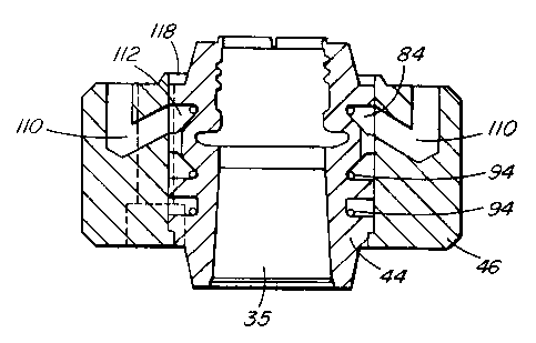
Reference is now made to Figures 8 and 9 which

show the hollow outer part 46 which is machined of a
suitable material such as tool steel. As can be seen, the
hollow outer part 46 is made with four retaining bolt holes

104 as well as a central opening 106 extending therethrough
with an inner surface 108. The inner surface 108 is made
to fit around the outer surface 80 of the hollow inner part
44. The hollow outer part 46 is also machined to have

outer portions 110 of two cooling fluid conduits which are
made to align respectively with the inner portions 84 of
the two cooling fluid conduits in the outer surface 80 of
the inner part 84.

Nickel brazing paste 94 is applied to the inner
portions 84 of the cooling conduits and the hollow inner
part 44 is inserted into the central opening 106 through
the hollow outer part 46 to form the pair of thread split
inserts 12, 14. As can be seen in Figures 10 and 11, this
completes the inner portions 84 of the cooling conduits in

the hollow inner part 44 which are aligned with the


CA 02244511 1998-07-29
12

corresponding outer portions 110 of the cooling conduits in
the hollow outer part 46. This produces the two cooling
conduits 112 through which cooling water flows from inlets
114 to outlets 116 on the front end 26. Nickel brazing

material is inserted into circular groove 118 and the
assembled hollow inner and hollow outer parts 44, 46 are
gradually heated in a vacuum furnace (not shown) to a
temperature of approximately 1925 F which is above the
melting point of the nickel alloy. As the furnace is

heated, it is evacuated to a relatively high vacuum to
remove substantially all of the oxygen and then partially
backfilled with an inert gas such as argon or nitrogen.
When the melting point of the nickel is reached, it melts
and flows by capillary action between the hollow inner part

44 and the hollow outer part 46 to integrally braze them
together to form the pair of thread split inserts 12, 14.
Brazing them together this way in the vacuum furnace
provides a metallurgical bonding between them to maximize
their strength and prevent leakage of the cooling water
from the cooling conduits 112.

After removal of the integral pair of thread
split inserts 12, 14 from the vacuum furnace, they are cut
in half along the longitudinal axis 96 in an electrical
wire-cut machine to form the two separate thread split

inserts 12, 14 shown in Figure 12. As shown, they are cut


CA 02244511 1998-07-29
13

in the correct plane to have one of the cooling conduits
112 in each of the thread split inserts 12, 14. The pair
of thread split inserts 12, 14 are then machined to provide
a good outer finish and the tapered portions 120, 122 at

their front and rear ends 26, 28. During molding the pair
of thread split inserts 12, 14 are secured tightly together
by the tapered flange portions 120, 122 being engaged by
the rest of the mold (not shown). In this position, the
matching flat inner surfaces 30, 32 abut and the curved

inner surfaces 34 of the pair of thread split inserts 12,
14 combine to form the opening 35 therethrough shaped to
mold the outer surface 18 of the neck portion 16 of the
preform 10. Of course, during molding an elongated
cylindrical core (not shown) extends through this opening
35 to form the inner surface 124 of the preform 10.

In use in a multi-cavity mold, a number of pairs
of thread split inserts 12, 14 made according to the
invention are mounted in a conventional mold. A supply of
cooling water or other suitable cooling fluid is connected

to the inlet 116 of the cooling fluid conduit 112 in each
thread split insert 12, 14 to circulate through each
cooling fluid conduit 112. Pressurized melt from a molding
machine is then injected into the cavity in the opening 35
through each pair of thread split inserts 12, 14 according

to a predetermined injection cycle. After the cavities are


CA 02244511 1998-07-29

14
full, injection pressure is held momentarily to pack and
then released. After a short cooling period, the mold is
opened to eject each preform 10. This is done by the
preform 10 first being ejected from the core and the two

thread split inserts 12, 14 then separated to drop the
preform 10 onto a conveyor belt or cooling plate. Of
course, this requires that the two thread split inserts 12,
14 be separated enough to release the ring collar 20 and
threads 22 of the preform 10. After ejection, the mold is

closed and injection pressure is reapplied to refill the
cavity and the injection cycle is repeated continuously.
While the description of the method of making the

pair of thread split inserts 12, 14 has been given, with
respect to a preferred embodiment, it will be evident that
various other modifications are possible without departing

from the scope of the invention as understood by those
skilled in the art and as defined in the following claims.

Representative Drawing
A single figure which represents the drawing illustrating the invention.
Administrative Status

For a clearer understanding of the status of the application/patent presented on this page, the site Disclaimer , as well as the definitions for Patent , Administrative Status , Maintenance Fee  and Payment History  should be consulted.

Administrative Status

Title Date
Forecasted Issue Date 2008-12-23
(22) Filed 1998-07-29
(41) Open to Public Inspection 2000-01-29
Examination Requested 2003-07-21
(45) Issued 2008-12-23
Deemed Expired 2018-07-30

Abandonment History

There is no abandonment history.

Payment History

Fee Type Anniversary Year Due Date Amount Paid Paid Date
Application Fee $300.00 1998-07-29
Maintenance Fee - Application - New Act 2 2000-07-31 $100.00 2000-06-13
Maintenance Fee - Application - New Act 3 2001-07-30 $100.00 2001-06-27
Maintenance Fee - Application - New Act 4 2002-07-29 $100.00 2002-06-27
Maintenance Fee - Application - New Act 5 2003-07-29 $150.00 2003-06-26
Request for Examination $400.00 2003-07-21
Maintenance Fee - Application - New Act 6 2004-07-29 $200.00 2004-06-22
Maintenance Fee - Application - New Act 7 2005-07-29 $200.00 2005-06-22
Maintenance Fee - Application - New Act 8 2006-07-31 $200.00 2006-06-21
Maintenance Fee - Application - New Act 9 2007-07-30 $200.00 2007-06-20
Registration of a document - section 124 $100.00 2007-10-11
Registration of a document - section 124 $100.00 2007-11-16
Registration of a document - section 124 $100.00 2008-02-21
Maintenance Fee - Application - New Act 10 2008-07-29 $250.00 2008-06-23
Final Fee $300.00 2008-10-02
Maintenance Fee - Patent - New Act 11 2009-07-29 $250.00 2009-06-25
Maintenance Fee - Patent - New Act 12 2010-07-29 $250.00 2010-06-25
Maintenance Fee - Patent - New Act 13 2011-07-29 $250.00 2011-06-27
Maintenance Fee - Patent - New Act 14 2012-07-30 $250.00 2012-06-26
Registration of a document - section 124 $100.00 2013-04-08
Maintenance Fee - Patent - New Act 15 2013-07-29 $450.00 2013-06-26
Registration of a document - section 124 $100.00 2013-10-01
Maintenance Fee - Patent - New Act 16 2014-07-29 $450.00 2014-06-23
Maintenance Fee - Patent - New Act 17 2015-07-29 $450.00 2015-06-26
Maintenance Fee - Patent - New Act 18 2016-07-29 $450.00 2016-06-21
Owners on Record

Note: Records showing the ownership history in alphabetical order.

Current Owners on Record
MOLD-MASTERS (2007) LIMITED
Past Owners on Record
4437667 CANADA INC.
GELLERT, JOBST ULRICH
Past Owners that do not appear in the "Owners on Record" listing will appear in other documentation within the application.
Documents

To view selected files, please enter reCAPTCHA code :


To view images, click a link in the Document Description column. To download the documents, select one or more checkboxes in the first column and then click the "Download Selected in PDF format (Zip Archive)" or the "Download Selected as Single PDF" button.

List of published and non-published patent-specific documents on the CPD .

If you have any difficulty accessing content, you can call the Client Service Centre at 1-866-997-1936 or send them an e-mail at CIPO Client Service Centre.


Document
Description 
Date
(yyyy-mm-dd) 
Number of pages   Size of Image (KB) 
Representative Drawing 2000-01-10 1 7
Representative Drawing 2008-11-28 1 12
Cover Page 2008-11-28 2 52
Cover Page 2000-01-10 1 41
Abstract 1998-07-29 1 32
Description 1998-07-29 13 451
Claims 1998-07-29 3 91
Drawings 1998-07-29 6 143
Claims 2006-02-17 6 223
Claims 2006-10-19 6 193
Assignment 1998-07-29 3 94
Correspondence 2001-01-12 7 332
Correspondence 2001-01-25 1 1
Correspondence 2001-01-25 1 2
Prosecution-Amendment 2003-07-21 1 46
Correspondence 2008-04-30 6 289
Fees 2004-06-22 1 38
Correspondence 2004-07-08 2 58
Correspondence 2004-07-12 9 581
Correspondence 2004-07-20 1 13
Correspondence 2004-07-20 1 15
Fees 2005-06-22 1 28
Prosecution-Amendment 2006-01-11 1 28
Prosecution-Amendment 2006-02-17 8 270
Prosecution-Amendment 2006-04-19 2 34
Fees 2006-06-21 1 29
Prosecution-Amendment 2006-10-19 9 270
Prosecution-Amendment 2007-06-12 2 36
Fees 2007-06-20 1 29
Assignment 2007-11-16 26 1,192
Prosecution-Amendment 2007-12-12 3 118
Assignment 2008-02-21 8 447
Assignment 2008-02-29 6 334
Fees 2008-06-23 1 36
Correspondence 2008-10-02 1 33
Assignment 2007-10-11 30 792
Assignment 2013-04-08 9 505
Assignment 2013-10-01 32 1,186