Language selection

Search

Patent 2244845 Summary

Third-party information liability

Some of the information on this Web page has been provided by external sources. The Government of Canada is not responsible for the accuracy, reliability or currency of the information supplied by external sources. Users wishing to rely upon this information should consult directly with the source of the information. Content provided by external sources is not subject to official languages, privacy and accessibility requirements.

Claims and Abstract availability

Any discrepancies in the text and image of the Claims and Abstract are due to differing posting times. Text of the Claims and Abstract are posted:

  • At the time the application is open to public inspection;
  • At the time of issue of the patent (grant).
(12) Patent Application: (11) CA 2244845
(54) English Title: IMPROVEMENTS IN OR RELATING TO FIRE ASSEMBLIES
(54) French Title: AMELIORATIONS DE RADIATEURS A GAZ
Status: Deemed Abandoned and Beyond the Period of Reinstatement - Pending Response to Notice of Disregarded Communication
Bibliographic Data
(51) International Patent Classification (IPC):
  • F24B 1/189 (2006.01)
  • F24B 1/18 (2006.01)
  • F24B 7/04 (2006.01)
(72) Inventors :
  • KINDER, JOHN MICHAEL (United Kingdom)
  • GREEN, MICHAEL JOHN (United Kingdom)
(73) Owners :
  • KINDER FIRES LIMITED
(71) Applicants :
  • KINDER FIRES LIMITED (United Kingdom)
(74) Agent: RICHES, MCKENZIE & HERBERT LLP
(74) Associate agent:
(45) Issued:
(86) PCT Filing Date: 1997-02-04
(87) Open to Public Inspection: 1997-08-14
Availability of licence: N/A
Dedicated to the Public: N/A
(25) Language of filing: English

Patent Cooperation Treaty (PCT): Yes
(86) PCT Filing Number: PCT/GB1997/000310
(87) International Publication Number: WO 1997029327
(85) National Entry: 1998-07-29

(30) Application Priority Data:
Application No. Country/Territory Date
9602382.5 (United Kingdom) 1996-02-06

Abstracts

English Abstract


Gas fire assembly (10) comprising a turbine (32) rotatably mounted in a first
conduit (18) through which exhaust gases pass. The turbine (32) is drivably
connected to freely rotatable fans (40, 42) located in a second conduit
located immediately behind the gas burner (12), such that convected air is
warmed in the second conduit (22) and pulled therethrough by the fans (40, 42)
to push convected air into a room space.


French Abstract

L'invention concerne un radiateur à gaz (10). Ce radiateur comprend une turbine (32) montée rotative dans une première conduite (18) à travers laquelle passent les gaz d'échappement. La turbine (32) est reliée, en vue de son entraînement, à des ventilateurs tournant librement (40, 42) placés dans une deuxième conduite située immédiatement derrière le bec de gaz (12). Ainsi, l'air convecté est chauffé dans la deuxième conduite (22) et aspiré dans cette dernière par les ventilateurs (40, 42) pour pousser l'air convecté dans l'espace de la pièce.

Claims

Note: Claims are shown in the official language in which they were submitted.

Claims:-
1. A fire assembly (10) for heating a room space, comprising a first conduit
(18,46,48,50) to allow flue gases from the heating means (12) to exhaust from
the assembly (10), a second conduit (22) arranged in association with the
heating means (12) such that air in the second conduit is heated by the heating
means (12), characterised in that the assembly also comprises vapour operated
drive means (30) arranged in the first conduit (18,46,48,50), and air impeller
means (40,42,56) drivably connected to the drive means (30), the assembly (10)
being arranged such that flue gases exhausting through the first conduit
(18,46,48,50) operate the drive means (30) to drive the impeller means
(40,42,56) thereby to impel heated air through the second conduit (22) to heat
the room space.
2. An assembly according to claim 1, characterised in that the air impeller
means comprises a rotary member (40,42,56) arranged to be rotatable by the air
drive means (30).
3. An assembly according to claim 2, characterised in that the rotary
member comprises a fan (40,42,56) to impel the air through the second conduit
(22).
4. An assembly according to any of claims 1 to 3, characterised in that the
first conduit (18,46,48,50) extends through the second conduit (22).
5. An assembly according to claim 4 when dependent on claims 2 or 3,
characterised in that the air impeller means comprises rotary members (32,54)
arranged respectively on either side of the first conduit (18).
6. An assembly according to claim 5, characterised in that a plurality of
first conduits (46,48,50) are provided, each extending through the second
conduit (22), with drive means (54) in each first conduit, and respective
rotary members (56) arranged on either side of some or all of the first

conduits (46,48,50).
7. An assembly according to any of the preceding claims, characterised in
that the drive means (30) is arranged to be rotated by flue gases from the
heating means (12).
8. An assembly according to claim 7, characterised in that the drive means
(30) comprises one or more turbines (32,54) arranged to be rotatable by flue
gases exhausted from the fire assembly (10).
9. An assembly according to any of the preceding claims, characterised in
that the drive means (30) is connected by connection means (34,58) to the
impeller means (40,42,56).
10. An assembly according to claim 9, characterised in that the connection
means comprises a shaft (34,58) extending through the or each first conduit
(18,46,48,50) and the second conduit (22), upon which shaft (34,58) the drive
means (30) and impeller means (40,42,56) are mounted.
11. An assembly according to any of the preceding claims, characterised in
that the heating means comprises a gas fired burner (12).
12. An assembly according to any of the preceding claims, characterised in
that the second conduit (22) extends from an air inlet (24) at a lower region ofthe fire assembly (10) to an air outlet (26) at an upper region of the fire
assembly (10).
13. An assembly according to any of the preceding claims, characterised in
that the fire assembly (10) comprises a front and a rear region, the heating
means (12) preferably being provided at said front region and the second
conduit (22) preferably being provided at said rear region.
14. An assembly according to claim 13, characterised in that a chamber (16)

is provided at said front region to house the heating means (12).
15. An assembly according to claim 14 when dependent on claim 12,
characterised in that the air inlet (24) for the second conduit (22) is providedbelow said chamber (16).
16. An assembly according to claims 14 or 15 when dependent on claim 12,
characterised in that the air outlet (26) for the second conduit (22) is provided
above said chamber (16).
17. An assembly according to any of claims 14 to 16, characterised in that
heat exchange means is provided on the rear of the chamber (16) within the
second conduit (22).
18. An assembly according to any of claims 14 to 17, characterised in that
the or each first conduit (18,46,48,50) extends from an inlet or inlets opening
into said chamber (16) to an outlet at the rear of said fire assembly.
19. An assembly according to claim 18, characterised in that the or each first
conduit (18,46,48,50) is arranged towards the upper region of said fire assembly(10).

Description

Note: Descriptions are shown in the official language in which they were submitted.


CA 02244845 l998-07-29
PCT/GB97/00310
W O 97~9327
IMPROVEMENTS IN OR RELATI~G TO FIRE ASSEr~ TFS
This invention relates to fire assemblies. More particularly, but not
exclusively, this invention relates to convection type fire assemblies.
i
Conventiona~ convection type gas fires operate by providing a convection
conduit at the rear of the fire which is heated by the gas burner. The air in the
conduit is thus heated, which is passed by convection into the room. Ways
have been sought in order to enhance the flow of air through the convection
conduit.
According to the invention there is provided a fire assembly for heating a
room space, comprising a first conduit to allow vapour from the heating means
to exhaust from the assembly, a second conduit arranged in association with
the heating means such that air in the second conduit is heated by the heating
means, vapour operated drive means arranged in the first conduit, and air
impeller means drivably connected to the drive means, the assembly being
arranged such that vapour exhausted from the heating means operates the
drive means to drive the irnpeller means thereby to impel heated air through
the second conduit to heat the room space.
Preferably, the air impeller means comprises a rotary member arranged
to be rt)tatable by the air drive means. Preferably, the rotary member comprisesa fan to impel the air through the second conduit. Preferably the first conduit
extends through the second conduit and the air impeller means may comprise
rotary members arranged respectively OIl either side of the first conduit. A
p~urality of first conduits may be provided, each extending through the second
conduit, with drive means in each first conduit, and respective rotary members
arranged on either side of some or all of the first conduits.
..
The drive means is preferably arranged to be rotated ~y vapour from the
heating means. The drive means may comprise one or more turbines arranged
to be rotatable by vapour exhausted from the fire assembly.

CA 02244845 l998-07-29
PCT/GB97/00310
WO g7129327
Preferably, the drive means is connected by connection means to the
impeller means. The connection means may comprise a shaft extending c
through the or each first conduit and the second conduit, upon which shaft the
drive means and impeller means are mounted. .;
Preferably, the heating means comprises a gas fired burner, and the
vapour exhausted from the fire assembly may comprise flue gas forrned during
the burning of gas in the burner.
The second conduit may extend from an air inlet at a lower region of the
fire assembly to an air outlet at an upper region of the fire assembly.
Preferably, the fire assembly comprises a front and a rear region, the heating
means preferably being provided at said front region and the second conduit
preferably being provided at said rear region. A chamber may be provided at
said front region to house the heating means. Preferably, the air irllet for thesecond conduit is provided below said chamber and the air outlet is preferably
provided above said chamber.
E~eat exchange means may be provided on the rear of the chamber within
the second conduit.
The or each first conduit preferably extends from an inlet or i}~ets
opening into said chamber to an outlet at the rear of said fire assembly.
Preferably, the or each first conduit is arranged towards the upper region of
said fire assembly.
Embodiments of the invention will now be described by way of example
only in which:
Fig. 1 is a schematic front, part sectional view of a fire assembly
according to the invention, showing a drive means and an impeller means;
~ ig. 2 is a view along the lines II-II in Fig. l;
Fig. 3 is a view along the lines III-III in Fig. 2; and
Fig. 4 fs a plan view of part of a modified assembly according to the
-
-

CA 0224484~ 1998-07-29
W O 97/29327 PCTIGB97/00310
invention.
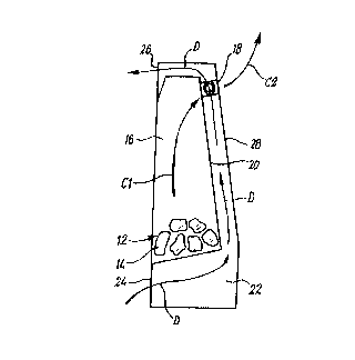
~ eferring to the drawings, there is shown a fire assembly 10 which is in
the form of a gas fire, for heating a room space. The fire assembly 10
comprises hearing means in the form of a gas burner 12. The gas burner 12
may be in the form of a live fuel effect burner, and may include imitation fuel,schematically represented at 14. The gas burner ~2 is connected to the mains
gas supply in the normal way.
The gas burner 12 is housed within a chamber 16 which is in
communication with the region external of the fire assembly 10 via a first
conduit 18. The chamber 16 is isolated from the room space to prevent flue
gases entering the room space.
When the gas burner 12 is burning, flue gases are emitted which pass
from the burner 12 in the direction of the arrow Cl to be exhausted from the
fire assembly 10 via the first conduit 18 in the direction of the arrow C2. The
flue gases are usually then passed by a chimney or other appropriate
construction to a region outside the ~ ling
The chamber 16 is defined at the rear by a back wall 20. A: second
conduit 22 extends from an inlet 24 at a lower region of the fire assembly 10 toan outlet 26 at an upper region of the fire assembly 10. ~he second conduit 22
extends behind the chamber 16 and is defined by the back wall 20 of the
chamber 16 and a rear wall 2~ of the fire assembly 10.
When the gas burner 12 is in operation, to burn gas fed from the mains,
the heat produced thereby warms the back wall 20 which, in turn, warms the air
in the second conduit 22 directly behind the back wall 20.
. ~
The air in the second conduit 22 then rises by convection in the direction
of the arrows D. The rising air in the section of the conduit 22 behind the backwall 20 creates a partial vacuum which causes air to be sucked into the conduit

CA 0224484~ 1998-07-29
W 097/29327 PCT/GB97/00310
22 from outside the fire assembly 10 via the inlet 24. The rising air then passes
out of the conduit 22 via the outlet 26 to warm the room.
Vapour operated drive means 30 is mounted in the first conduit 18. The
drive means 30 comprises a turbine 32 mounted on a shaft 34.
As can be seen, the first conduit 18 extends through the second conduit
22 centrally thereof. The first and second conduits 18, 22 are isolated from
each other by walls 36,38. The sha~t 34 extends from the turbine 32 through
the walls 36,38 and is journalled in suitable bearings in the walls 36,38.
Appropriate sealing means are provided to ensure that the flue gases passing
through the first conduit 18 do not leak into the second conduit 22.
Mounted on the shaft 34 in the second conduit 22, at either side of the
turbine 32 are first and second rotary fans 40,42, the purpose of which is to
impel air through the second conduit 22 thereby enhancing the warming of the
room as effected by convection.
In operation, the turbine 32 iS rotated about the shaft 3~ by the flue
gasses passing through the first conduit 18. Since the turbine 32, and the fans
40,42 are each fixedly mounted on the shaft 3~, the rotation of the turbine 32
causes corresponding rotation of the fans 40,42. The fans 40, 42 are provided
with a plurality of vanes 44, which are so angled that rotation thereof by the
rotating turbine 32 causes the fans 40,42 to impel air in the direction of the
arrows D. This impelling of the air by the fans ~0,42 enhances the ~low of
warrn air through the second conduit 22 over that which would be caused by
convection alone, thereby improving the efficiency of the fire assembly 10.
The flue gases will be pulled by the chimney or other structure through j~
the first conduit 18. The taller the chirnney, generally the greater the pull
provided thereby. In conventional fires this can be disadvantageous in taldng
heat too quickly from the fire. ~owever, in assemblies according to the
invention, the greater the pull the greater the speed of rotation of the turbine

CA 0224484~ 1998-07-29
W O 97/29327 PCT/GB97/00310
30 and hence fans 40,42, and thus the circulation of hot air into the room
space.
Fig. 4 shows a modified arrangement with three first conduits 46,48,50
extending through the second conduit 22 which is hence divided into four parts
52. The central first conduit 48 is larger than the two side first conduits Ds6~50
and each first conduit is equispaced from each other and the sides of the
second conduit 22, by the parts 52. Each first conduit 46,48,aO locates a
respective size turbine 54, and fans 56 are located in each of the parts 52. Theturbines 54 and fans 56 are all mounted on a shaft 58. This arrangement
provides for a more even draw off of flue gases, and also better heat transfer.
Various other modifications can be made without departing from the
scope of the invention. For example, the first conduit 18 could be arranged to
pass through the second conduit 22 at ~~ne side thereof. In such an
arrangement, the fans 40,42 could be replaced by a single fan. In fact a wide
variety of configurations of the first and second conduits are possible. Also,
instead of a direct drive between the turbine 32 and the fans ~0,42 an
appropriate gearing arrangement could be provided. Heat exchanger means
such as fins, could be provided on the rear of the back wall 20 and/or elsewhereto assist heating of the air passing through the second conduit.
Whilst endeavouring in the foregoing specification to draw attention to
those features of the invention believed to be of particular importance it should
be understood that the Applicant claims protection in respect of any patentable
feature or combination of features hereinbefore referred to and/or shown in the
drawings whether or not particular emphasis has been placed thereon.

Representative Drawing
A single figure which represents the drawing illustrating the invention.
Administrative Status

2024-08-01:As part of the Next Generation Patents (NGP) transition, the Canadian Patents Database (CPD) now contains a more detailed Event History, which replicates the Event Log of our new back-office solution.

Please note that "Inactive:" events refers to events no longer in use in our new back-office solution.

For a clearer understanding of the status of the application/patent presented on this page, the site Disclaimer , as well as the definitions for Patent , Event History , Maintenance Fee  and Payment History  should be consulted.

Event History

Description Date
Inactive: IPC from MCD 2006-03-12
Application Not Reinstated by Deadline 2001-02-05
Time Limit for Reversal Expired 2001-02-05
Deemed Abandoned - Failure to Respond to Maintenance Fee Notice 2000-02-04
Inactive: Single transfer 1998-12-04
Inactive: First IPC assigned 1998-11-07
Classification Modified 1998-11-07
Inactive: IPC assigned 1998-11-07
Inactive: Courtesy letter - Evidence 1998-10-13
Inactive: Notice - National entry - No RFE 1998-10-10
Application Received - PCT 1998-10-05
Application Published (Open to Public Inspection) 1997-08-14

Abandonment History

Abandonment Date Reason Reinstatement Date
2000-02-04

Maintenance Fee

The last payment was received on 1998-07-29

Note : If the full payment has not been received on or before the date indicated, a further fee may be required which may be one of the following

  • the reinstatement fee;
  • the late payment fee; or
  • additional fee to reverse deemed expiry.

Please refer to the CIPO Patent Fees web page to see all current fee amounts.

Fee History

Fee Type Anniversary Year Due Date Paid Date
Registration of a document 1998-07-29
MF (application, 2nd anniv.) - small 02 1999-02-04 1998-07-29
Basic national fee - small 1998-07-29
Owners on Record

Note: Records showing the ownership history in alphabetical order.

Current Owners on Record
KINDER FIRES LIMITED
Past Owners on Record
JOHN MICHAEL KINDER
MICHAEL JOHN GREEN
Past Owners that do not appear in the "Owners on Record" listing will appear in other documentation within the application.
Documents

To view selected files, please enter reCAPTCHA code :


To view images, click a link in the Document Description column. To download the documents, select one or more checkboxes in the first column and then click the "Download Selected in PDF format (Zip Archive)" or the "Download Selected as Single PDF" button.

List of published and non-published patent-specific documents on the CPD .

If you have any difficulty accessing content, you can call the Client Service Centre at 1-866-997-1936 or send them an e-mail at CIPO Client Service Centre.


Document
Description 
Date
(yyyy-mm-dd) 
Number of pages   Size of Image (KB) 
Abstract 1998-07-29 1 50
Description 1998-07-29 5 232
Claims 1998-07-29 3 98
Drawings 1998-07-29 1 33
Cover Page 1998-11-12 1 36
Representative drawing 1998-11-12 1 5
Notice of National Entry 1998-10-10 1 192
Courtesy - Certificate of registration (related document(s)) 1999-02-01 1 115
Courtesy - Abandonment Letter (Maintenance Fee) 2000-03-06 1 185
PCT 1998-07-29 11 359
Correspondence 1998-10-13 1 29