Note: Descriptions are shown in the official language in which they were submitted.
CA 0224~07~ 1998-07-31
WO 97128349 PCT/GB97/0~1308
IMPROVED DOWNHOLE APP~RATUS
This invention relates to apparatus for use in
downhole operations. In particular, but not exclusively,
the apparatus relates to an lsolation valve intended for
use in completion testing and in operations which take
place immediately following completion testing.
In the oil and gas exploration and extraction
industries, deep bores are drilled to gain access to
hydrocarbon-bearing strata. The section of bore which
intersects this strata or "production zone" is typically
provided with a steel "llner", while the section of bore
extending to the surface is lined with steel "casing". Oil
and gas is extracted from the production zone through
production tubing extending through the casing from the
upper end o~ the liner. The production tubing is formed of
a string of threaded sections or "subs" which are fed
downwards from the surface, additional subs being added at
the surface until the string is of the desired length. As
the string is assembled and fed into the bore its pressure
integrity, or "completion", is tested at regular intervals.
Such testing is also carried out on the complete string.
The testing is accomplished by pressurising the internal
bore of the string. Of course this re~uires that the
string bore is sealed at its lower end.
This sealing of the string bore is generally
accomplished using a valve or plug which will normally
remain closed or in place once testing is completed, to
CA 0224~07~ 1998-07-31
W097128349 PCT/Gs97/00308
allow the packers mounted on the string to be set to locate
and seal the string within the casing or liner. The valve
or plug may then be opened or removed to permit ~ormation
~luid to ~low upwardly to the sur~ace through the
production tubing. The opening or removal operation
generally requires running in of an appropriate tool on,
~or example, wireline or coiled tubing, which will involve
additional time and expense.
It is among the objectives o~ embodiments o~ this
invention to obviate or mitigate these disadvantages. It
is a ~urther objective o~ embodiments o~ this invention to
provide an isolation valve which will hold pressure in two
directions, that is ~rom the sump side and the sur~ace
side.
According to a ~irst aspect o~ the present invention
there is provided a downhole valve comprising a body
de~ining a bore, a valve closure member positioned in the
bore, first and second retaining members positioned on
respective sides o~ the valve closure member ~or ret~; n; n~
2~ the valve closure member in a closed position and to hold
pressure ~rom both sides, one o~ the ret~i n; ng members
being retractable to permit opening o~ the valve closure
member.
In use, such a downhole valve will hold pressure ~rom
both the sur~ace side and the sump side. The terms "above"
and "below" are used herein, but those o~ skill in the art
will o~ course realise that the invention may be used with
equal utility in inclined or horizontal bores, and the
CA 0224~07~ l998-07-3l
W097l28349 PCTIGB97/00308
orientation of the valve may be varied.
Preferably, with the valve closure member in the open
position, the body defines a slick bore.
Preferably also, the valve closure member c-omprises a
flapper in the form of a disc. Most preferably, the disc
is in the form of a curved or concave disc. In the
preferred embodiment a convex surface of the disc engages
a valve seat.
Preferably also, one of the retaining members is
extendable to maintain the valve closure member in an open
position and to provide a slick bore. In the preferred
embodiment one o~ the retaining members is both
retractable, to permit opening of the valve closure member,
and extendable to maintain the valve closure member in the
open position.
Preferably also, one of the ret~;ning members
incorporates a valve seat. The valve seat may include an
elastomeric seal located in an end surface of the retaining
member. Most preferably, the retaining member
incorporating the valve seat is non-retractable.
Alternatively, a separate valve seat may be provided.
Preferably also, the retractable retaining member is
moveable by application of fluid pressure thereto. The
fluid pressure may be provided by well fluid in the
borehole, and most pre~erably by the well fluid in the body
bore. The supply of fluid from the body bore to actuate
the retaining member may be controlled by an appropriate
valve, such as described in PCT\GB95\02046.
CA 0224~07~ l998-07-3l
W097/28349 PCT/GB97/00308
Preferably also, the retractable retaining member
includes a sleeve portion de~ining a piston, such that
application o~ fluld pressure between the sleeve portion
and the body tends to retract the member from a retaining
position. The member may be biassed towards the ret~; n; ng
position by biassing means, such as a spring.
Pre~erably also, the retractable retaining member is
lockable in the retaining position, but is releasable, most
pre~erably on application of actuating fluid pressure.
Most preferably, the unlocking of the retractable retaining
member is controlled by a ratchet assembly comprising first
and second axially relatively movable parts, each part
de~ining a toothed face, and a ratch member located between
the toothed ~aces, pressure induced reciprocal movement of
the parts advancing the ratch member axially along the
toothed face of the first part, in an advanced position the
ratch member engaging a unlocking member such that further
movement o~ the first part actuates the unlocking member to
release the retaining member.
Additionally, or alternatively, the retractable
retaining member may be releasable by application of
physical force by a further tool located in the bore.
~referably, the unlocking member de~ines a tool engaging
profile for cooperating with said further tool.
2~ Preferably also, the retractable retaining member may
be latched in the retracted position, to permit opening of
the valve closure member, and then released to return to an
extended position ~o maintain the valve closure member open.
CA 0224~07~ 1998-07-31
W097/28349 PCT/GB97/00308
Preferably also, the valve closure member is in the
form o~ a ~lapper and is mounted on a valve carriage which,
with the ret~;n;ng member retracted, is axially movable
towards the retaining member such that the ret~ln;ng member
may contact the flapper and push the flapper towards the
open position. The valve carriage and the retaining member
are preferably connected by a resilient link. In the
preferred embodiment, retraction of the retaining member is
achieved by pressurising the bore, which also maintains the
valve carriage and ~lapper in the closed position, with the
~lapper in sealing contact with the other retaining member.
Bleeding o~f bore pressure ~ollowing retraction of the
retaining member allows the ~1apper to lift from the other
retaining member and the valve carriage to follow the
retracted retaining member, and the end of the retaining
member to contact the ~lapper and push the ~lapper to the
open position.
The valve may include vent means for equalising
pressure across the valve closure member prior to the
Z0 retractable retaining member permitting opening. The vent
means may be openable by initial application of ~luid
pressure, to permit ~luid communication across the valve
member. Most preferably, the vent means includes a
moveable member, such as a sliding sleeve, which initially
closes a vent passage but is moveable to open the passage.
Pre~erably also, the moveable member also serves, in its
initial position, to lock the retractable retaining member
in the retaining position.
CA 0224~07~ l998-07-3l
W097/28349 PCT/GB97/00308
The other o~ the retaining members may be biassed to
move the valve closure member to the open position.
Alternatively, the valve closure member may be provided
with means ~or biassing the member towards the open
position.
According to another aspect of the present invention
there is provided a method o~ completing a downhole string
including the steps o~:
providing a valve in a tubular strlng, which valve is
~0 capable o~ holding pressure from both above and below;
running the string into a bore with the valve closed;
securing the string in the bore; and
opening the valve to permit ~low o~ fluid through the
string.
Conventionally, in a completion operation, the string
is provided with a normally-closed valve which opens in
response to higher pressure in the well to permit well
~luid to ~low into the string. Thus, such valves are not
suitable ~or use as sa~ety valves, and separate sa~ety
valves must be provided in the string to sa~eguard against
surges o~ fluid up through the string when upper end o~ the
string is opened. A valve which will hold pressure from
both the sump and sur~ace sldes allows ~or completion
testing against the valve and may also serve as a sa~ety
2~ valve. In the method o~ this aspect o~ the invention top
~illing may be utilised ~or ~illing the string with ~luid
as i_ is run into the bore.
According to a further aspect o~ the present invention
CA 0224~07~ l998-07-3l
Wog7/2~349 PCT/GB97/00308
..
there is provided a downhole valve comprising: a curved
valve closure member defining a convex ~ace and a seal area
on said ~ace; and a valve seat ~or engaging the seal area.
Preferably, the valve includes a tubular valve body
having a main axis and the seal area defines a surface
which is substantially perpendicular to said axis.
According to a still ~urther aspect of the present
invention there is provided a downhole valve for holding
fluid pressure in a first direction, the valve including a
non-planar valve closure member defining a peripheral seal
surface and a valve seat having a corresponding sealing
area, the seal sur~ace and sealing area being substantially
perpendicular to said first direction.
It has been ~ound that the sealing capabilities of
valves in accordance with this aspect of the invention
compare favourably in comparison with valves in which the
seal surface simply coincides with the surface of the valve
closure member.
Pre~erably, the valve closure member is a curved
~lapper, and most preferably the seal sur~ace is provided
at the periphery of the convex ~ace of the member.
Preferably also, the sealing area includes a resilient
sealing portion.
According to a yet further aspect o~ the present
invention there is provided a ratchet arrangement ~or
downhole apparatus, the arrangement comprising first and
second parts, each part de~ining a toothed face, and a
ratch member located between the toothed ~aces, the parts
CA 0224~07~ l998-07-3l
W097/28349 PCT/GB97/00308
being axially relatively movable by application o~ fluid
pressure thereto, wherein reciprocal movement of the parts
advances the ratch member axially along the toothed ~aces.
The ratch member may engage a part of another tool or
device on reaching an advanced position, and serve to
actuate the tool or device or transfer force thereto from
one o~ the parts. In a preferred embodiment the ratch
member is utilised to trans~er force ~rom the ~irst part to
unlock a further part o~ a valve to permit opening o~ the
valve.
Pre~erably, the ~irst part defines a piston and is
movable on application o~ fluid pressure thereto, and the
first part has a stroke corresponding to the tooth spacing
on the toothed ~aces o~ the parts such that each pressure
cycle will advance the ratch member one tooth.
Accordingly, by providing a known number o~ teeth and
knowing the initial position o~ the ratch ~ember, the ratch
member may be moved to a predetermined advanced position by
application of a predetermined number of pressure cycles.
This ~eature is useful when used in conjunction with
pressure actuated tools ~or use in completion operations,
where pressure is used in, ~or example, completion testing
and setting packers. Using this aspect of the invention,
t~e operation o~ a particular pressure actuated tool, such
2~ as an isolation valve, may be controlled by the ratchet
assembly, and will only commence after a predetermined
number o~ pressure cycles, thus accommodating completion
testing operations and the setting of packers.
CA 0224~07~ 1998-07-31
W097128349 PCT/GB97/00308
9 ~.
The piston and toothed ~ace o~ the ~irst part may be
lntegral. Alternatively, the toothed ~ace may-~orm part o~
a unit, incorporating the other toothed face and the ratch
member, which is separable ~rom the tool or device provided
in combination with the ratchet assembly.
Pre~erably, the ratch m,ember comprises ~irst and
second portions and a spring portion acting therebetween to
urge the ~irst and second portions into engagement with the
respective toothed ~aces. Pre~erabl~, the ratch member
portions are combined as a single integral part.
These and other aspects o~ the present invention will
now be described, by way o~ example, with re~erence to the
accompanying drawings, in which:-
Figure 1 is a sectional view o~ a downhole isolation
valve in accordance with a first embodiment o~ the presentinvention;
Figure lA illustrates the true cross-section at area
lA o~ Figure 1;
Figure 2 is a sectional view on line 2 - 2 o~ Figure
1;
Figure 3 is an enlarged view o~ a portion of the
isolation valve o~ Figure 1, with the valve closure member
in the closed position;
Figures 4, 5 and 6 are sectional views corresponding
to Figure 3, and illustrating the se~uence o~ events
culminating in the valve being locked open; and
Figure 7 is a sectional view o~ a downhole isolation
valve in accordance with a second embodiment o~ the present
CA 02245075 1998-07-31
WO 97128349 PCT/GB97/00308
invention;
Figures 8 and 9 are sectional views of a downhole
isolation valve in accordance with a preferred embodiment
of the present invention;
Figure 10 is a view from below of the valve disc of
the valve of Figure 8;;
Figure 11 ls a side view of the disc of Figure 10;
Figure 12 is a sectional view on line 12-12 of Figure
1 0 ;
Figure 13 is a plan view of the lower retaining sleeve
of the valve o~ Figure 8;
Figure 14 is a sectional view on line 14-14 of Figure
13;
CA 0224~07~ l998-07-3l
W097J28349 11 pcTlGs97loo3~8
isolation valve 20 in accordance with a first embodiment o~
the present invention.
The isolation valve 20 comprises a tubular body 22
provided with upper and lower end caps 24, 25 provided with
threaded ends ~or locating the body 22 in a tubular string
(not shown). A valve member in the form o~ a concave
circular disc 26 is mounted towards the upper end o~ the
body 22, and is initially locked closed. The disc 26 seals
against the ends o~ corresponding pro~iled upper and lower
sliding sleeves 30, 31 de~ining respective seals 32, 33.
The seals 32, 33 are pre-loaded by a compression spring 34
located= on the lower or sump side o~ the disc 26, and
acting between the lower end o~ the sleeve 31 and the lower
end cap 25, to provide low pressure sealing. Pressure on
lS the upper or surface side loads a snap ring 36 which locks
the lower end o~ the sleeve 31 relative to the body 26 (see
Figure lA ~or true cross-section at snap ring 36) .
Pressure ~rom the sump side loads the upper end cap 24, via
the upper sleeve 30. A compression spring 37 is provided
between the upper end cap 24 and the upper sliding sleeve
30 and is used in opening the disc 26, as will be
described.
There is an annular volume 38 de~ined between the
inner wall o~ the body 22 and the outer wall o~ the lower
sleeve 31. The volume 38 accommodates two sleeves: a disc
mounting sleeve 40, to which the disc 26 is hinged and
which is ~ixed to the body 22; and a sliding vent sleeve 42
which is axially movable within the volume 38. Rotational
CA 0224~07~ l998-07-3l
W09~28349 12 PCT/GB97/00308
movement of the sleeve 42 is restricted by a guide pin 44
extending through the sleeve 31. In its initial position
the vent sleeve 42 closes a vent passage 46 linking the
volume 38 with a volume 48 on the sur~ace side o~ the disc
26 which accommodates the spring 37. The sleeve 42 i8
initially fixed at the lower end o~ the volume 38 and is
held in position by a shear pin 50. The sleeve 42 de~ines
an annular groove 52 on its outer ~ace which accommodates
the snap ring 36 in its locked position. The sleeve 42
defines a shoulder 56 positioned above the outlet o~ a
~luid passage 58 which communicates, through appropriate
control lines and valves, to a supply o~ pressurised ~luid
or, most preferably, to a respective shuttle valve on a
control tool as described in PCT\GB95\02046 or
PCT\G~96\Q1907, the disclosures o~ which are incorporated
herein by re~erence; the shuttle valve permits ~luid
communication between the body bore and the passage 58.
As noted above, the valve 20 is run in the closed
position with the sump side compression spring 34 providing
a low pressure sealing ~orce. Pressure ~rom the sump side
acts over seals 32, 33 and also a seal 60 between the lower
end o~ the sleeve 31 and the body 22. The load generated
by this pressure is supported by the upper end cap 24.
Pressure ~rom the surface side acts over the seals 32, 33
and also the seal 62 between the upper end o~ the sleeve 30
and the body 22.
To open the valve 20, a control tool (not shown) as
described above is subject to a predetermined number of
CA 0224~07~ l998-07-3l
W097J2~349 p~TlGs97loo3o8
13
pressure cycles to open the appropriate shuttle valve,
allowing pressurised well ~luid to ~low into the passage
58. This pressure acts on the lower sliding vent sleeve
shoulder 56, shears the pin 50 and moves the sleeve 42
upwardly in the volume 48 li~ting the upper end o~ the
sleeve 42 clear o~ the vent passage 46, and permitting
~luid communication over the disc 26 and allowing the
pressure to balance between each side o~ the disc 26.
Upward movement o~ the sliding vent sleeve 42 also unlocks
the snap ring 36.
With the snap ring 36 unlocked, the lower sliding
sleeve 31 can now retract as the hydraulic ~luid pressure
~orce created in the volume 38 overcomes the biassing ~orce
produced by the spring 34. When the lower sleeve 31 is
1~ ~ully retracted, the upper sliding sleeve 30 ~orces the
disc 26 open under spring ~orce.
On hydraulic pressure being bled o~ ~rom the volume
38, the lower sliding sleeve 31 is returned to its initial
position by spring force. As the lower sliding sleeve 31
returns to its initial position it retains the disc 26 in
the open position, and provides a slick bore.
Re~erence is now made to Figure 7 o~ the drawings,
which illustrates a downhole isolation valve in accordance
with a second embodiment o~ the present invention. The
valve 70 comprises a tubular body 72 comprising an outer
- sleeve 73 with upper and lower end caps or sleeves 74, 75
threaded to the ends thereo~. A valve member in the ~orm
o~ a concave circular disc 76 is mounted towards the lower
CA 0224~07~ l998-07-3l
W 097~8349 PCT/G~97/0030S
14
end o~ the body 72, and is initially locked closed, as
illustrated in Figure 7. In the closed position the convex
disc suri~ace 77 is in sealing contact with a valve seat 78
defined by the upper end of a lower retaining sleeve 80.
The seat 78 includes a groove which accommodates an
elastomerlc seal 79. The lower end sleeve 75 provides a
mounting ~or the retaining sleeve 8 Q and a sealing O-ring
82 is provided therebetween.
The disc 76 is retained in the closed position,
against the valve seat 78, by an upper retaining sleeve 84
having a lower end which corresponds to the concave i~ace 86
o~ the disc 76. ~nitially, with the disc 76 locked closed,
the upper end o~ the retaining sleeve 84 i9 f~ixed against
axial movement relative to the outer sleeve 73 by a
1~; split\snap ring 88 located in an external annular groove 90
in the sleeve 84 and engaging an internal groove 92 on the
inner wall o:~ the outer sleeve 73. Part o~ the retaining
sleeve groove 90 is ~ormed in the upper portion of an
actuator sleeve 94, the lower portion oi~ which is slightly
enlarged and ~orms a piston within an annular chamber 96
~:,etween the outer wall o~ the retalning sleeve 84 and the
inner wall of~ the outer sleeve 73. The space between the
retaining sleeve 84 and the outer sleeve 73 above the
actuator sleeve 94 iS in communication with a pressurising
~luid line ~or connection to a control line (not shown~
linked to a pressurised ~luid source. The control line
leads into a ~luid communication line 98 ~ormed through the
upper end sleeve 74 and which line 98 continues through the
CA 0224~07~ 1998-07-31
W097l28349 pcTlGs97loo3o8
upper end of the outer sleeve 73 and opens into a small
chamber 100 at the upper end o~ the retaining sleeve 84.
Thus, application o~ ~luid pressure through the line 98
into the chamber 100 will ~orce the actuator sleeve 94
downwardly and push the split ring 88 radially outwardly
and ~ully into the groove 92, thus unlocking the retaining
sleeve 84 ~rom the outer sleeve 73.
On release o~ the split ring 88, the retaining sleeve
84 will not be immediately retracted, as the sleeve 84 is
biassed into the retalning position by a compression spring
104 provided in a spring housing 106 and which acts between
the lower ~ace o~ the upper end sleeve 74 and a shoulder
108 on the housing 106. However, by increasing the
pressure that is applied through the line 98 into the
chamber 100 an upwardly directed pressure ~orce will act
against the lower side o~ the spring housing shoulder 108
and above a predetermined bore\annulus pressure
di~erential this pressure ~orce will overcome the
retaining spring ~orce and retract the retaining sleeve 84.
The retraction o~ the sleeve 84 continues until a set of
latch ~ingers 110 engage an annular groove 112 on the outer
sur~ace o~ the retaining sleeve 84. The latch ~ingers 110
are mounted on a sleeve 114 located in the chamber 96 and
which is ~ixed relative to the outer sleeve 73 by anchor
pins 116.
The disc 76 is mounted, via a hinge pin 117, to a
valve sleeve or carriage 118 which is axially movable
within the chamber. The carrlage 118 is threaded to the
CA 0224~07~ l998-07-3l
W097l28349 PCT/GB97/00308
16
lower end o~ a trigger sleeve 120 linked to the retaining
sleeve 84 via a compression spring 122; the spring 122 acts
between a shoulder 124 towards the upper end o~ the sleeve
120 and a collar 126 ~ixed to the retaining sleeve 84. A
retaining sleeve 128 extends upwardly ~rom the upper end o~
the trigger sleeve 120.
When the retaining sleeve 84 is retracted as described
above, by application o~ bore pressure through the line 98
to the chamber 100, and has been latched in the retracted
posltion by the latch ~ingers 110, the pressure within the
bore retains the disc 76 in the closed position and in
contact with the va~ve seat 78. However, the relative
axial movement between the retaining sleeve 84 and the
valve carriage 118 on retraction o~ the sleeve 84 results
~5 in compression o~ the spring 122. Accordingly, as pressure
is bled o~ ~rom the bore, and the pressure di~erential
across the disc ~alls, the disc 76 will be lifted ~rom the
valve seat 78 by the extension o~ the spring 122. The
upward movement of the valve carriage 118 and disc 76
continues until the upper concave disc ~ace 86 contacts the
lower end o~ the retaining sleeve 84, which contact causes
the disc 76 to be pivoted to the open position.
Once the disc 76 has been pushed to the ~ully open
position, the upper end o~ the trigger sleeve 120 comes
into contact with the latch ~ingers 110 and li~ts the
~ingers 110 out o~ the groove 112 to latch with the ~inger
retaining sleeve 128, such that the valve disc retaining
sleeve 84 is ~ree to move downwardly once more under the
CA 0224~07~ l998-07-3l
W097/28349 17 PCT/~B97/00308
in~luence o~ the spring 104. The ~reed retaining sleeve 84
moves downwardly, to isolate the dlsc 76 between the sleeve
and the outer sleeve 73, and al90 such that the lower end
of the sleeve 84 comes into contact with the valve seat 78.
The valve is now held in the open position, with the sleeve
84 de~ining a slick bore past the open disc 76.
In the event that, for whatever reason, it is not
possible to open the valve solely by application o~ ~luid
pressure, a mechanical override sleeve 130 is provided
within the valve bore at the upper end o~ the retaining
sleeve 84. The outer wall o~ the sleeve 130 de~ines a
groove 132. A number o~ balls 134 are provided in the
groove and extend through corresponding openings 136 in the
retaining sleeve 84 and contact the inner sur~ace o~ the
split ring 88. Accordingly, when the sleeve 130 is pulled
upwardly using a suitable downhole tool, the balls 134 are
pushed outwardly through the openings 13 6 to push the split
ring 88 into the outer sleeve groove and release the
retaining sleeve 84 ~rom the outer sleeve 73. Further
20 upward movement o~ the sleeve 130 will li~t the retaining
sleeve 84 and permit the disc 76 to open, as described
above.
It will be evident that the valve 70 described above
will hold pressure ~rom both the sur~ace and sump sides,
but may be opened when desired either by application o~
bore pressure or by mechanical means, to provide an
unrestricted or slick bore.
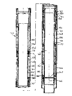
Re~erence is now made to Figures 8 and 9 o~ the
CA 0224~07~ l998-07-3l
WO97/28349 ~8 PCT/G~97/00308
drawings, which illustrate an isolation valve 140 in
accordance with a preferred embodiment of the present
invention. Like the embodiments described above, the valve
140 ~eatures a concave valve disc 142 and upper and lower
retaining members or sleeves 144, 146, and the disc
mounting and retaining arrangement is substantially similar
to the valve 70. However, this valve 140 is operated in a
somewhat different manner, in that the retractable
ret~ n, ng sleeve 144 is actuated by the pressure of well
fluid directly above the disc 142 wlthout requiring the
provision of a separate control tool, and the control of
the unlocking of the sleeve 144 is accomplished by an
arrangement forming part of the valve 140, rather a
separate control tool, as will be described.
I~ reference is made also to Figures 10 to 14 O~ the
drawings, the disc 142 and lower retaining member 146 are
illustrated in greater detail. The concave disc I42
defines a peripheral sealing area 147 on its convex face
which surface is perpendicular to the disc Z-axis. The
sleeve 146 defines a corresponding valve seat 149, defining
a gr~ove to receive a resilient seal member.
As with the valve 70 described above, the retractable
sleeve 144 is locked in position relative to the valve body
148 by a lock ring 150. A lock sleeve 152 holds the lock
ring 150 in a radially extended con~iguration in a groove
154 in the valve body 148 and in this position a shoulder
15Ç defined by the sleeve 144 abuts the ring 150,
restricting upward axial movement of the sleeve 144. The
lock sleeve 152 may be lifted to release the lock ring 150,
CA 0224~07~ l998-07-3l
W097/28349 19 PCT/G~97/00308
and thus release the retaining sleeve 144, by a ratch-
member 158 which is movable along an axial slot 160 in the
lock sleeve 152. The ratch member 158 is located between
two opposing toothed surfaces 162, 163 provided on
respective sleeves 164, 165. The inner sleeve 164 is
threaded to the upper end of the retractable retaining
sleeve 144, while the outer sleeve 165 is movable
independently of the sleeve 144, but is biassed downwardly
by a compression spring 166 which acts between the upper
end o~ the sleeve 165 and a shoulder ~ormed on the valve
body 148. The interaction of the ratch member 158 with the
toothed surfaces 162, 163, allows a number of pressure
cycles to be applied to the valve 140 before the retaining
sleeve 144 is unlocked to allow opening of the disc 142, a8
described below.
When the string and thus the valve bore 168 is
pressurised, fluid pressure acts on two piston areas 170,
171. The first piston area 170 is formed on the
retractable retaining sleeve 144 and is in communication
with the valve bore 168 vla ports 172. However, while the
sleeve 144 is locked relative to the valve body 148 by the
lock ring 150, no movement of the sleeve 144 may take
place. The second piston area 171 is defined by the sleeve
16S and is in communication with the valve bore 168 via
ports 173 in the inner sleeve 164. Application o~ a fluid
pressure force to the piston area 171 lifts the sleeve 165,
against the action of the spring 166, until a split collar
174 located ln an annular groove in the upper end of the
sleeve 165 engages a shoulder 176 defined by the inner
CA 0224~07~ l998-07-3l
WOs7/28349 pcTlGs97loo3o8
sleeve 164. This "stroke" o~ the sleeve 165 corresponds to
the length o~ one o~ the teeth o~ the toothed sur~ace 163.
Thus, as the sleeve 165 is li~ted by application o~ well
~luid pressure, the ratch member 158 is also li~ted a
corresponding distance, however when the ~luid pressure in
the valve bore 168 is reduced, and the spring 166 moves the
sleeve 165 downwards, the ratch member 158 is retained in
its advances position by the toothed sur~ace 162 o~ the
inner sleeve 164.
}0 I~ re~erence is made to Figure 15 o~ the drawings, it
will be noted that the ratch member 158 comprises two
inter-~itting part annular segments 180, 181 which are
urged into a radially extended position by a coil spring
182. A guide pin 184 is ~ixed to the inner segment 180,
and extends through an opening in an outer segment 181.
The pin 184 corresponds with an axial slot 186 in the outer
sleeve 165.
With each pressure cycle that is applied to the
string, the ratch member 158 is advanced one step along the
inner sleeve toothed sur~ace 162. A~ter a predetermined
number o~ cycles, the ratch member 158 reaches the end o~
the ~ock sleeve groove 160, such that the next increase in
pressure within the string and valve bore 168 will result
in the ratch member 158 li~ting the lock sleeve 152,
allowing the lock ring 150 to contract radially, and thus
~reeing the retaining sleeve 144 ~rom the valve body 148.
The subsequent sequence o~ events is similar to that
described with re~erence to the valve 70 described above,
as described brie~ly below.
CA 0224~07~ l998-07-3l
wo97n~349 21 PCT/GB97/00308
Once the retaining sleeve 144 has been released ~rom
the body 148, the ~luid pressure acting on the piston area
170 will tend to li~t the sleeve 144 relative to the valve
body 148, bringing the inner sleeve 164 into contact with
the outer sleeve 165 at the piston area 171, such that
subsequent movement of the sleeve 144 is resisted by the
action o~ the spring 166. While the sleeve 144 moves
upwardly, the disc 142 is maintained in contact with the
~alve seat 149 de~ined by the lower member 146 by the
pressure acting downwardly on the disc 142. As with the
above-described embodiment, the disc 142 is mounted on a
carriage 188 linked to the sleeve 144 v a a trigger sleeve
190 and a spring 192. The retraction o~ the sleeve 144
continues until latch ~ingers 194 mounted on the valve body
148 engage a pro~ile 196 on the sleeve 144.
I~ pressure is then bled o~ ~rom the valve bore 168
above the disc 142, the pressure ~orce maintaining the disc
142 in contact with the lower seat ~alls, until, when the
pressure across the disc 142 is almost equalised, the
spring 192 li~ts the carriage 188 and disc 142 towards the
end o~ the sleeve 144. The upper sur~ace o~ the disc 142
will then be brought into contact with the lower end o~ the
sleeve 144 and will be pushed into the open position. When
the disc 142 is ~ully open, a trigger nose 198 provided on
the upper end o~ the trigger sleeve 190 releases the latch
~ingers 194, such that the action o~ the spring 166 pushes
the sleeve 144 downwardly to retain and isolate the disc
142 in the open position.
Re~erence is now made to Figures 16 to 20 o~ the
CA 0224~07~ l998-07-3l
W097/28~49 22 PCT/GB97/00308
drawings, which illustrate part of a valve 198 and a
modi~ied ratch assembly 200, in accordance with aspects of
the present invention. The ratch assembly 200 operates in
a manner which is substantially the same as the ratch
assembly described above, however, this assembly 200
includes a unit 202 (Figure 18), consisting of the first
and second toothed tracks 204, 205 and the ratch member
206, which is removable ~rom the r~m~;n~er of the device.
The sleeve 208 incorporating the piston 210 which induces
movement of the first toothed track 204 is mounted on the
valve, separately from the unit 202, and may be connected
to an upper portion of the track 204 using an appropriate
~astener.
The unit 202 is located in the valve by passing the
unit 202 through a suitable door in the valve body (not
shown) into a longitudinally extending aperture 212 in an
upper portion o~ the unlocking member 214 (Figure 17
illustrates the position of the unlocking member 214 a~ter
it has been li~ted by the ratch member 206).
The ratch member 206 is formed of a single wedge-
shaped block of metal in which a key-hole slot has been cut
to permit deformation of the block as it climbs the tracks
204, 205.
In use, two units 202 will be fitted to the valve
after the assembled valve has been tested, such that there
is no requirement to reset the ratch members following
testing. This provides an additional advantage in that it
is no longer necessary to form a slot in the valve body
along the length of the toothed tracks, as required in the
CA 0224~07~ l998-07-3l
W097/28349 23 PCT/GB97/00308
above described embodiment, to allowing resetting of the
ratch member; the presence of the slot leads to a weakening
of the valve body.
It will be clear to those of skill in the art that the
valves described above may be used in many downhole
applications, and offer many advantages over conventional
isolation valves and plugs. The valves may be opened
merely by appropriate application of bore pressure, and
thus obviate the need for intervention using, for example,
wireline mounted tools Further, the valves may be located
at any convenient location in a string and may be
positioned below a packer or other apparatus if desired.
It will further be clear to those of skill in the art that
the above-described embodiments are merely exemplary of the
present invention, and that various modifications and
improvements may be made thereto without departing from the
- scope of invention as defined in the appended claims.