Language selection

Search

Patent 2245286 Summary

Third-party information liability

Some of the information on this Web page has been provided by external sources. The Government of Canada is not responsible for the accuracy, reliability or currency of the information supplied by external sources. Users wishing to rely upon this information should consult directly with the source of the information. Content provided by external sources is not subject to official languages, privacy and accessibility requirements.

Claims and Abstract availability

Any discrepancies in the text and image of the Claims and Abstract are due to differing posting times. Text of the Claims and Abstract are posted:

  • At the time the application is open to public inspection;
  • At the time of issue of the patent (grant).
(12) Patent Application: (11) CA 2245286
(54) English Title: WAVE PROPULSION DEVICE
(54) French Title: PROPULSEUR A VAGUES
Status: Deemed Abandoned and Beyond the Period of Reinstatement - Pending Response to Notice of Disregarded Communication
Bibliographic Data
(51) International Patent Classification (IPC):
  • B63H 01/37 (2006.01)
  • A01K 85/14 (2006.01)
  • A01K 85/18 (2006.01)
  • B63H 01/14 (2006.01)
  • B63H 01/36 (2006.01)
  • B63H 19/02 (2006.01)
  • B64C 11/00 (2006.01)
  • F03B 13/14 (2006.01)
(72) Inventors :
  • MANCUSO, ROBERT BRIAN (Canada)
(73) Owners :
  • ROBERT BRIAN MANCUSO
(71) Applicants :
  • ROBERT BRIAN MANCUSO (Canada)
(74) Agent:
(74) Associate agent:
(45) Issued:
(22) Filed Date: 1998-09-04
(41) Open to Public Inspection: 2000-03-04
Availability of licence: N/A
Dedicated to the Public: N/A
(25) Language of filing: English

Patent Cooperation Treaty (PCT): No

(30) Application Priority Data: None

Abstracts

English Abstract


An externally powered propulsion device particularity designed
to propel floating and submerged water craft, as well as
any other vehicles (land or air). The device utilizes a
helical coil drive mechanism which causes a flexible body
plate(s) to move and undulate in such a way that a travelling
unilineal wave motion is produced. The resulting wave creates
thrust within any fluidic medium. (See attached description for
more detailed information.)
In brief, the device is designed to transform mechanical
standing wave motion into a travelling wave pattern applicable
as a propulsion mechanism.
The device is also broadly applicable in many situations
where a travelling wave pattern may be desirable for reasons
not related to vehicular propulsion (e.g., pumps, fans, fishing
lures, massaging devices, conveyers, amusement devices, etc.).


Claims

Note: Claims are shown in the official language in which they were submitted.

CLAIMS
The embodiments of the invention
in which an exclusive property
or privilege is claimed are defined
as follows:
1 A device for propelling or driving
an object through a liquidic or
gaseous medium by means of
undulating travelling lineal wave
action, comprising a rotating helical
or spiral coil or spiral crankshaft
threaded or inserted through an
assemblage or series of slotted plates
flexibly attached or hinged together.
2 A device as defined in claim 1,
in which the helical coil, comprised of
sufficiently rigid material of variable
length with variable number of loops,
is rotated around its central
longitudinal axis by means of an
external power source.
3 A device as defined in claim 1, in
which the plate assemblage is
comprised of a variable number of
sufficiently rigid plates of variable
else flexibly attached or swing hinged
together with edges parallel to each
other or end to end or leading edge to
trailing edge in a repetitive lineal
sequence.
4 A device as defined in claim 1,
in which the flexible attachment or
hinging mechanism only allows for one
way swinging side to side lateral
movement of each plate relative to the
other along an axis 90 degrees to the

long axis of the connected plate edges,
by means, for example, of hinges
connecting both the top and bottom
edges of adjoining plates.
A device as defined in claim 1, in
which each plate consists of an open
slot hole running continually from
leading to trailing end inside of each
plate with its longest lateral axis
aligned parallel to the long axis of the
hinged or flexibly attached plate edge.
8 A device as defined in claim 1,
except, instead of plate assemblage
and flexible connections as defined
respectively in claims 3 and 4, utilizes
a one piece flattened unibody housing
or sleeve comprised of flexible material
such as rubber, plastic, etc., of which
the lateral height of the hollow cavity,
is longer at 90 degrees to the lateral
width of the hollow cavity to supplant
the slot mechanism as defined in
claim 5.
7 A device as defined in claims 1
through 6, except for the purpose
of creating jet or pumping action,
in which the entirety of the
embodiments are positioned
lengthwise or longitudinally
within a squared cylinder or tube in
such a way that all nonhinged plate
edges and wave peaks of undulating
plate assemblage meet parallel and
flush or with minmal clearance to
cylinder or tube walls, creating a
constant and travelling four
way seal tracking along all contact
points in a sequence.
6

8 A device as defined in claims 1
through 7, except not externally
powered as defined in claim 2,
in which the device is operated in
reverse action by pulling it
through a fluidic or gaseous medium,
or by fixing the device in a stationary
position within a head-on flow of a
fluidic or gaseous medium.
7

Description

Note: Descriptions are shown in the official language in which they were submitted.


CA 02245286 1999-12-02
SPECIFICATION Application No. : 2,245,285
The device is uniquely designed as a means to simply transform
mechanical standing helical or spiral wave motion into a travelling
lineal wave pattern applicable as a propulsion mechanism within a
liquidic or gaseous medium. The invention replicates both fish
swimming body motiom and propulsion.
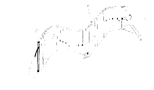
In drawings which illustrate embodiments of the invention, Figure 1
is a 8 dimensional representation of the invention from a side view
perspective, Figure 2 is an expanded view of a single slotted plate
and a section of the coil, Figure 3 is a top view of the invention,
Figure 4 is a front endl view of the invention, Figure 5 is a view of
the coil only, and Figure 6 is a close up view of hinging mechanisms
Joining two plates.
The device consists of a sufficiently rigid elongated helical coil (Fig. 1-1,
Fig. 4-5, Fig. 5j or spiral coil or spiral crank shaft and, using example as
depicted in Figure 1, a horisontai row of sufficiently rigid slotted plates
(Fig. 1-2j hinged or flexibly attached one to another (Fig. 6j.
The coil is threaded through all plate slots (Fig. 2, Fig. 3-4) and the front
leading end of the coil (Fig. 1-3j is centrally connected to a rotating
shaft driven by an energetic source such as an electric motor, gasoline
engine, elastic band, human muscle power, etc.
The hinging or flexible attachment mechanism only allows for one way
swinging side to side !lateral movement of each plate relative to the
other along an axis 8Q~ degrees to the long axis of the connected plate
edges, by means, for example, of hinges connecting both the top and
bottom edges of adjoining plates.
The number and size c~f coil laops and plates varies according to any
particular application.
Externally applied energy causes the coil to rotate its loops around
a common central axis (longitudinally in line with the motor shaft)
(Fig. 4~5, Fig. 5j. The rotating coil creates an undulating screwing
movement also described as a 3 dimensional sinuose standing wave
pattern (Any point in the coil rotates along a fixed arc around the axis.)
(Fig. 1, Fig. 3j. The screwing movement can run forward or backward,
depending on the rotational direction of the coil.
Each plate moves laterally back and forth or side to side across the
central axis (Fig. 4j, while remaining in a vertical upright postion, as the

CA 02245286 1999-12-02
plate tracks with the point of the coil with which it is attached (in
contact with) by means of the slots (Fig. 1, Fig. 2, Fig. 3,4). With
each revolution of the coil, a plate is forced to one side as a point
in the coil (at slot contact point) reaches maximal lateral hor,zontal
distance from the central axis (Fig. 2, Fig. 4). As the contact point
in the coil moves toward the maximal vertical ditance above or below
the central axis, the contact point of the coil slides up or down inside
the slot (Fig. 2) allowing the plate to move horizontally with the point
in the coil toward the central axis with out any vertical (up and down)
movement. The coil can not push the plate up or down, only left or
rightl side to side because the vertical slot permits vertical free play,
while maintaining constant horizontal contact between the coil and
the plate. The result is a graduated movement of the plate from one
side of the axis to the other; from 0 horizontal movement, when the
coil contact point is positioned within the extreme top or bottom of
the slot, to maximum horizontal movement, when the coil is
positioned in the middle of the slot. Any tendency for vertical
movement of the plates, due to frictional or inertial forces are
overcome or neutralised by means of the plates being connected
together (Fig. 6-6, Fig.g-7). Bath the combined weight of the plates and
differential coil and slot relationships existent in the plate assemblage
work to counter the effect of any vertical plate movement. Also,
because the plate ass~embiage is attached to a leading plate (housing
the connection between coil end and motor shaft) which contains no
coil/ slot contact mechanism, the leading plate serves to stabilize
wayward movement of the plates (The leading plate is connected to
the assemblage by means of a horizontally swinging hinge mechanism.).
Angular rotational movement of the unit as a whole is countered
by the use of stabilizing fins (Fig. 1) and weights positioned low on the
body (Fig. 1), if the device is to be used as a self contained vehicle in
itself. Otherwise, the idevice can be attached directly to the
super structure of the vehicle it propels.
The combined effect of all plate movement is an undulating lineal
wave pattern, or serpentine motion, (Fig. 1, Fig. 3) travelling along the
horizontal axis from one end to the other of the plate assemblage.
Each plate is differentially positioned in relation to other plates with
the result that when one plate is at the crest postion of the wave
cycle, another is located at the trough position, while others
represent various intermediate positions along the wave curve. Each
2

CA 02245286 1999-12-02
plate, in turn, reaches any point in the wave profile according to a
graduated sequence, creating an over all multiphasic wave pattern.
in effect, each rotational cycle of every plate , at all times,
contributes, in part, to the development of an overall transcendent
"S' wave pattern comprised of many differentially fixed cycles working
in concert.
The crest peak of the resultant or transcendental wave moves along
(a travelling wave), tracking the points where each wave cycle reaches
maximal horizontal distance away from the central axis, one after the
other. All other points in the transcendent wave also represent the
same action sequence, except they track the rising/ falling or centering
(positioned at center axis) points of individual plate cycles. The leading
edge of the transcendent wave consists of individual plates rising
horizontally in sequence, while the trailing side of the wave is comprised
of individual plates sequentially returning back to the central axis along
a horisontal path. Once each plate returns or falls back to and crosses
the central axis, it immediately begins the rising phase of the cycle again.
The direction of the transcendent wave pattern movement against a
medium such as water creates thrust in the opposite direction because
the sum of the advancing forces on the leading aids of the wave curve
(effect of rising plate :sequence) exceeds the sum of the forces exerted
by the receding side of the wave curve (effect of retreating plate
sequence). The extended flat sides of the wave aid propulsion.
Propulsion effect of the device can occur in any kind of fluidic or
gaseous medium.
in reverse action effect, pulling the device in an unpowered state
through water, air, etc., so that water pressure forces out standing
plates to recede in sequence, causes the plates to undulate
according to a travelling wave pattern, producing a torque force in
the coil (coil rotates).
Modification allows for entire plate assemblage to be replaced with a
flexible flattened sleeve-like unibody housing consisting of material
such as rubber, plastic, etc. of which the lateral height of the hollow
cavity, is longer at 90 degrees to the lateral width of the hollow cavity
to supplant the slot mechanism.
3

CA 02245286 1999-12-02
Applications for the device are as follows:
Propulsion device for floating and submerged watercratt utilising
the linear wave action to create thrust. The unit can replace
conventional propeller mechanisms or be incorporated directly into
the the body structure of watercraft in that the outer hulls become
the propulsion mechanism. Advantages over conventional screw
propellers: more ~cient (harmonic rhythmic motion/ gaps, as is
the case with propeil~:r blades, are non existent between thrusting
platesl little or no cavitation), more quiet (minimal perturbation),
safer (no sharp cutting edges), and less likely to become snagged in
materials such as seaweed (no external screwing action).
A propulsion device for aircraft utilising high speed lineal wave motion
incorporated into the wing and or body structure or as an attachment.
Fishing lure utilizing realistic features of swimming body movement of
marine creatures such as fish as created by the device. The body of a
fish-like lure is constructed from flexibly joined plates actuated by a coil
mechanism. Dragging the lure through water will cause the lure body
to undulate and mimic fish movement. A propeller attached to the
leading or trailing end of coil shaft will facilitate coil rotation.
Massaging/ therapeutic device utilizing the wave motion as a means
to soothe or invigorates human bodily tissues.
A means to harness and utilise energy (e.g., transform wind/ ocean
wave power into usable energy) by exposing the device to head-on
liquidic of gaseous pr~asures, especially when the device is in a
stationary fixed position. The rotating coil can be utilized to perform
work, for example, by coupling a free end of the coil to an
electrical generator.
Pump to move fluldic or gaseous material (Device pieced longitudinally
within a square tunnell wlll allow little or no space between actuator and
tunnel wall, resulting iin less back seepage because the device also acts
as a seal). In this case, the device is utilised to create Jet or pumping
action by placing the ~:ntirety of the embodiments lengthwise or
longitudinally within a squared cylinder or tube in such a way that ail
nonhinged plate edgeac and wave peaks of undulating plats assemblage
meet parallel and flush or with minmal clearance to cylinder or tube
walls, creating a constant and travelling four way seat tracking along
all contact points in a sequence.
4

Representative Drawing
A single figure which represents the drawing illustrating the invention.
Administrative Status

2024-08-01:As part of the Next Generation Patents (NGP) transition, the Canadian Patents Database (CPD) now contains a more detailed Event History, which replicates the Event Log of our new back-office solution.

Please note that "Inactive:" events refers to events no longer in use in our new back-office solution.

For a clearer understanding of the status of the application/patent presented on this page, the site Disclaimer , as well as the definitions for Patent , Event History , Maintenance Fee  and Payment History  should be consulted.

Event History

Description Date
Inactive: IPC from MCD 2006-03-12
Application Not Reinstated by Deadline 2004-09-07
Inactive: Dead - RFE never made 2004-09-07
Deemed Abandoned - Failure to Respond to Maintenance Fee Notice 2004-09-07
Letter Sent 2003-09-15
Inactive: Abandon-RFE+Late fee unpaid-Correspondence sent 2003-09-04
Reinstatement Requirements Deemed Compliant for All Abandonment Reasons 2003-08-29
Inactive: Adhoc Request Documented 2003-06-06
Deemed Abandoned - Failure to Respond to Maintenance Fee Notice 2002-09-04
Application Published (Open to Public Inspection) 2000-03-04
Inactive: Cover page published 2000-03-03
Inactive: Correspondence - Formalities 1999-12-02
Classification Modified 1998-12-02
Inactive: First IPC assigned 1998-12-02
Inactive: IPC assigned 1998-12-02
Inactive: First IPC assigned 1998-12-02
Inactive: IPC assigned 1998-12-02
Inactive: Filing certificate - No RFE (English) 1998-10-09
Application Received - Regular National 1998-10-07

Abandonment History

Abandonment Date Reason Reinstatement Date
2004-09-07
2002-09-04

Maintenance Fee

The last payment was received on 2003-08-29

Note : If the full payment has not been received on or before the date indicated, a further fee may be required which may be one of the following

  • the reinstatement fee;
  • the late payment fee; or
  • additional fee to reverse deemed expiry.

Patent fees are adjusted on the 1st of January every year. The amounts above are the current amounts if received by December 31 of the current year.
Please refer to the CIPO Patent Fees web page to see all current fee amounts.

Fee History

Fee Type Anniversary Year Due Date Paid Date
Application fee - small 1998-09-04
MF (application, 2nd anniv.) - small 02 2000-09-05 2000-09-01
MF (application, 3rd anniv.) - small 03 2001-09-04 2001-08-31
MF (application, 4th anniv.) - small 04 2002-09-04 2003-08-29
Reinstatement 2003-08-29
MF (application, 5th anniv.) - small 05 2003-09-04 2003-08-29
Owners on Record

Note: Records showing the ownership history in alphabetical order.

Current Owners on Record
ROBERT BRIAN MANCUSO
Past Owners on Record
None
Past Owners that do not appear in the "Owners on Record" listing will appear in other documentation within the application.
Documents

To view selected files, please enter reCAPTCHA code :


To view images, click a link in the Document Description column. To download the documents, select one or more checkboxes in the first column and then click the "Download Selected in PDF format (Zip Archive)" or the "Download Selected as Single PDF" button.

List of published and non-published patent-specific documents on the CPD .

If you have any difficulty accessing content, you can call the Client Service Centre at 1-866-997-1936 or send them an e-mail at CIPO Client Service Centre.


Document
Description 
Date
(yyyy-mm-dd) 
Number of pages   Size of Image (KB) 
Representative drawing 2000-02-13 1 14
Abstract 1998-09-03 1 23
Description 1998-09-03 3 214
Drawings 1998-09-03 2 53
Description 1999-12-01 4 206
Claims 1999-12-01 3 64
Filing Certificate (English) 1998-10-08 1 163
Notice: Maintenance Fee Reminder 2000-06-05 1 118
Notice: Maintenance Fee Reminder 2001-06-04 1 120
Notice: Maintenance Fee Reminder 2002-06-04 1 120
Courtesy - Abandonment Letter (Maintenance Fee) 2002-10-01 1 182
Second Notice: Maintenance Fee Reminder 2003-03-04 1 121
Reminder - Request for Examination 2003-05-05 1 113
Notice: Maintenance Fee Reminder 2003-06-04 1 115
Notice of Reinstatement 2003-09-14 1 167
Courtesy - Abandonment Letter (Request for Examination) 2003-11-12 1 166
Notice: Maintenance Fee Reminder 2004-06-06 1 118
Courtesy - Abandonment Letter (Maintenance Fee) 2004-11-01 1 176
Correspondence 1998-10-12 1 37
Correspondence 1999-12-01 9 324
Fees 2003-08-28 1 36
Fees 2001-08-30 1 25
Fees 2000-08-31 2 91