Note: Descriptions are shown in the official language in which they were submitted.
CA 02245359 1998-11-17
TITLE: PRESSURE MODULATION VALVE ASSEMBLY
INVENTOR: ROGER W. FINCHER
FIELD OF THE INVENTION
The field of this invention relates to drilling string pressure modulation
valves,
particularly those useful in combination with a drill string thruster used in
conjunction
with a drilling motor during drilling.
BACKGROUND OF THE INVENTION
One way drilling a borehole can be accomplished is by circulation of fluid
through a downhole motor which is operably connected to the drill bit. Such
bottom
hole assemblies have, at times in the past employed thrusters in an effort to
improve
drilling efficiency. The thruster is a telescoping tube arrangement which
allows the
drill bit to advance while the tubing string is supported in a rather
stationary position
at the surface. Ultimately, when the thruster has advanced its full stroke, or
a
notable potation thereof, the drill sting is lowered from the surface which
causes the
upper end of the thuster to slide down and therein close the thruster for the
next
stroke. When the drilling Kelley or the stand being drilled down by the top
drive
reaches the drill rig floor, circulation is interrupted and another piece of
tubing is
added to the string at the surface or the coiled tubing is further unspooled
into the
wellbore. This also causes the thruster to retract as a result of this
procedure and
the drilling procedure using the downhole motor begins once again.
In the past, depending on drilling conditions, fluid resistance in the
downhole
motor varies as a result of torque generated at the drill bit which is
connected to the
drilling motor. Fluctuations of pressure drop through the motor caused by the
above
noted bit torque change has in the past impeded the function of the thruster.
What
had occurred in the past was that the thruster responded to changes in
pressure
drop through the downhole motor instead of simply feeding out pipe as the
drill bit
advanced at at a constant weight on bit (WOB). The inability of the thruster
to
sense relatively constant pressures, regardless of the amount of work the
drilling
motor was required to do, caused instability to such thrusters to the point of
-1-
CA 02245359 1998-11-17
negating their functional operation and negatively impacting the drilling
operation.
What occurred was a pressure increase due to higher torque load on the motor
as a
result of changing drilling conditions. The higher or increased pressure was
sensed
at the thruster causing it to extend the telescoping portion out further which
in turn
increased the weight on the bit. Ultimately, with increasing weight on bit the
motor
torque was greater and the pressure sensed by the thruster was therein greater
and
drilling would cease as the thruster drove the motor in a stall condition
where the
drill bit is no longer turning.
In these past applications of the thruster, the weight on bit was a function
of
the pressure difference between inside and outside the thruster. The greater
the
difference the more force on the bit is exerted by the thruster. As a result,
assemblies using thrusters with downhole motors in combination with drill bits
have
not been as effiecent and useful as possible.
An object of this invention is to provide a pressure modulation valve in the
bottom-hole assembly between the thruster and the downhole motor to compensate
for pressure increases as a result of changing drilling conditions which have
in the
past caused an increase in torque and as a result winched the WOB applied by
the
thruster. Ultimately, it is the function of this invention to make a thruster
operable
when used in conjunction with the drilling motor so that it can efficiently
and reliably,
without undue cycling or oscillation, feed out pipe in response to advancement
of
the drill bit during the drilling operation. Use of the pressure modulation
valve
facilitates a constant weight on the bit since variations in pressure drop in
the
circulating mud in the drilling motor do not affect the relative force exerted
on the bit.
With the modulation feature fully effective, these variations in pressure drop
are
compensated by the pressure modulation valve with the result being a
facilitation of
a constant weight on bit regardless of motor differential pressure.
SUMMARY OF THE INVENTION
A drill string pressure modulation valve is disclosed which is usable in
combination with a downhole drilling motor and a drill string thruster to
compensate
for changes in pressure drop through the drilling motor which normally occur
during
-2-
CA 02245359 1998-11-17
drilling. When conditions change during drilling, which in turn changes the
pressure
drop through the drilling motor, the drill string pressure modulation valve
compensates for such changes to minimize the effect of such changes on the
operation of the thruster and the resulting WOB created by the thruster. The
modulation valve has a feature which allows it to find automatically a
balanced
preload condition for the main needle valve, the primary functional element
within
the modulation valve each time the rig pumps are turned off and then turned
on.
The modulation valve is fully self-contained, and is assembled as part of the
bottom-
hole assembly. The device senses the no-load pressure drop in the system and
sets itself each time the rig pumps are turned on to compensate for any change
in
the no-load pressure drop experienced below the device which could be
attributable
to such things as motor wear, bit nozzle plugging, or changes in the flow
rate.
Accordingly, the hydraulic thrusting force remains constant over a wide range
of
drilling environments. As the drilling conditions change and the pressure drop
in the
downhole motor increases, the needle valve shifts to compensate for such
additional
pressure drop with a resultant small or no effect on the thruster and the
resulting
WOB created by the thuster located upstream of this modulation value.
DETAILED DESCRIPTION OF THE DRAWINGS
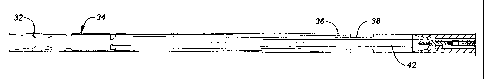
Figure 1A-C illustrates a bottom-hole assembly in a sectional, elevation view
showing the layout of the components, as well as a possible location for a
measurement while drilling system which can be used in tandem with the
apparatus.
Figure 2A-B is a sectional view of the drill string pressure modulation valve
in
the run-in position without the rig pump circulating.
Figure 3A-B is the view of Figure 2A-B with the pumps circulating, but the bit
off bottom.
Figure 4A-B is the view of Figure 3A-B with the pumps running and the drill
bit on bottom.
-3-
' CA 02245359 1998-11-17
DETAILED DESCRIPTION OF THE PREFERRED EMBODIMENT
The drill string modulation valve of the present invention is illustrated in
the
bottom-hole assembly illustrated in Figure 1A-C. A drill or tubing string 32,
which
can be rigid jointed pipe, reeled pipe or coiled tubing, supports a drill
string thruster
34 and related bottom hole assembly elements. The thruster 34 has an outer
housing 36 and an internal pipe 38. The internal pipe 38 is reciprocally
mounted
within the outer housing 36 and extends as the drill bit 40 advances. The
thruster
34 is responsive to pressure difference between internally of the bottom-hole
assembly, referred to as 42, and externally in an annulus around the assembly,
referred to as 44. The apparatus A is connected to the internal pipe 38. Below
the
apparatus A, a measurement while drilling system can be inserted to supply
data to
the surface regarding formation conditions and/or the rotary orientation of
the drill
motor assembly 40. The bottom-hole assembly of Figure 1 A-C also indicates an
upper stabilizer 46 and a lower stabilizer 48 between which is a drilling
motor 50.
Optionally, to assist in drilling deviated wellbores, bent subs 52 and 54 can
be
employed in the bottom-hole assembly as well as, or alternatively, other
desirable
steering arrangements may be used.
This type of a bottom-hole assembly is typically used for deviated wellbores.
The drilling motor 50 can be a progressive cavity type of a motor which is
actuated
by circulation from the surface through the drill string 32. The weight or
force on the
drill bit 40 is determined by the pressure difference internally to the
thruster 34 at
point 42 and the annular pressure outside at point 44. The drilling motor 50
is a
variable resistance in this circuit in that the pressure drop across it is
variable
depending on the load imposed on the motor 50 by troque created at the drill
bit 40.
For example, as drilling begins, the bit 40 causes an increase in load on the
drilling
motor 50 which increases the pressure drop between the drilling motor 50 and
the
annulus 44. That increase in pressure drop raises the pressure difference
across
the thruster 34 (if the apparatus A is not used) by raising the pressure at
point 42
with respect to the pressure at point 44. As a result, the thruster 34 adds an
-4-
CA 02245359 1998-11-17
incremental force through the drilling motor 50 down to bit 40. As additional
weight
is put on the bit 40, the drilling motor 50 increasingly bogs down to the
point where
this cycle continues until the drill bit 40 stalls the motor 50 due to the
extreme
downward pressure that is brought to bear on the bit 40 from the ever
increasing
internal pressure at point 42 inside the thruster 34. The thruster 34 instead
of
feeding out the internal pipe 38 in direct compensation for the advancement of
the
bit 40 instead is urged by the rise in pressure internally at point 42 to feed
out the
internal pipe 38 at a greater rate than the advancement of the bit 40, thus
adding the
force on bit, which in turn finally stalls the drilling motor 50. This had
been the
problem and the apparatus A of the present invention, when inserted in the
bottom-
hole assembly, as shown in Figure 1 B, addresses this problem. The apparatus A
acts as a compensation device, which, as its objective, keeps the pressure
constant
as possible at the internal point 42 of the thruster 34 despite variations in
pressure
drop that the drilling motor 50 created during drilling.
Referring now to Figure 2A and B, the apparatus A has a containment sub 1
which has a lower end 56 which is oriented toward the drilling motor 50, and
an
upper end 58, which is oriented toward the thruster 34. In order to describe
the
operation of the apparatus, the p~'essure adjacent lower end 56 will be
referred to as
P,; the pressure adjacent the upper end will be referred to as Pz; and the
annulus
pressure outside the containment sub 1 will be referred to as P3. Again, the
objective is to keep Pz as constant as possible.
The assembly shown in Figure 2 starts near the upper end with lifting head 2
which is supported from the containment sub 1 at thread 60. Attached to the
lower
end of the lifting head 2 is compressive pad 4, which in turn is secured to a
porous
metal filter 7. Below the porous metal filter 7, liquid that gets through it
flows
through mud flow port 6 to a cavity 62 above delay valve piston 9. Delay valve
piston 9 is sealed at its periphery by seal 64 to divide the delay valve tube
8 into
cavity 62 and cavity 66. Delay valve spring 10 resides in cavity 66 and biases
the
delay valve piston 9 toward the porous metal filter 7. A delay valve orifice
assembly
12 is located at the lower end of the delay valve tube 8. This is an orifice
which, in
-5-
CA 02245359 1998-11-17
essence, regulates the displacement of clean fluid in cavity 66 into cavity
68. Those
skilled in the art will appreciate that movement of delay valve piston 9
downhole
toward the lower end 56 will result in displacement of clean fluid, generally
an oil,
from cavity 66 through delay valve orifice block 11 into cavity 68 for
ultimate
displacement of piston valve 15. Piston valve 15 is sealed internally in delay
valve
tube 8 by seal 70. The piston valve 15 has a receptacle 72, which includes a
seal
74, which ultimately straddles the low-pressure transfer tube 16, as shown by
comparing Figure 2A to Figure 3A. The low pressure transfer tube 16 extends to
compensation tube body 20. Inside of compensation tube body 20 is compensation
spring 22. Spring 22 bears on compensation piston 76 at one end and on the
other
end against modulating ram needle 27. Needle 27 is sealed internally in the
compensation tube body 20 by seal 78. The compensating piston 76 is also
sealed
within the compensation tube body 20 by seal 80. Both the compensating piston
76
and the needle 27 are movable within the compensating tube body 20 for reasons
which will be described below. In effect, the piston 76 and the needle 27
define a
cavity 82 within the compensation tube body 20. The low pressure transfer tube
16
spans the entire cavity 82, but is not in fluid communication with that
cavity. A vent
port 23 is in fluid communication with cavity 82. The port 23 is in fluid
communication with cartridge vent port 24, which ultimately leads to transfer
groove
25, which in turn leads to the porous metal filter 26. Accordingly, the
pressure P3 is
communicated into the cavity 82. Port 24 can be sized to make cavity 82
operate as
a dampener on the movements of needle 27. It can be directly connected to P3
as
shown or to an external or internal reservoir. The reservoir can have a
floating
piston with one side exposed to P3 through the filter 26. This layout can
reduce
potential plugging problems in filter 26.
Referring now toward the lower end of the compensation tube body 20, the
needle 27 extends beyond an opening 84 and into the restrictor orifice 31. The
preferred components for the needle 27 and the restrictor orifice 31 is a
carbide
material. As illustrated in Figure 2B, the pressure at the inlet of the
drilling motor 50
-6-
CA 02245359 1998-11-17
(see Figure 1 B) is the pressure P,, which is also illustrated in Figure 2B.
Normal
flow to the motor 50 occurs from upper end 58 through passage 86 down around
needle 27 and out lower end 56.
In the position shown in Figure 2A, the low pressure transfer tube 16
communicates with cavity 88, which in turn through openings or ports 17
communicates with cavity 90. Those skilled in the art will appreciate that as
long as
the seals 74 do not straddle the top end of the low pressure transfer tube 16,
the
pressure P, at the lower end 56 communicates through low pressure transfer
tube
16 through cavity 88 and into cavity 90 so that the pressure P, acts on the
area of
the compensating piston 76 exposed to cavity 90. A seal 92 retains the
pressure P,
in cavity 90 while, at the same time, allowing the compensating piston 76 to
move
with respect to the low pressure transfer tube 16. The low pressure transfer
tube 16
is secured to the needle 27 and is placed in alignment with a longitudinal
passage
94 in the needle 27. A seal 96 separates the pressure P,, which exists in
passage
94 and in low pressure transfer tube 16, from pressure P3, which exists in
cavity 82.
Seal 78 serves a similar purpose around the periphery of the needle 27.
The significant components of the apparatus now having been described, its
operation will be reviewed in more detail. Figures 2A-B reflect the apparatus
A in
the condition with the surface pumps turned off. In that condition, the spring
22
pushes the compensation piston 76 against delay valve tube 8 and, at the same
time, pushes the needle 27 against the ledge formed by opening 84. At the same
time the delay valve spring 10 pushes the delay valve piston 9 against
hydrostatic
pressures applied through the upper end 58 through the porous metal filter 7
and
mud flow port 6. At this point with no flow, P,=PZ and the delay valve piston
9 is in
fluid pressure balance.
When the surface pumps are turned on, the first objective of the apparatus A
of the present invention is to obtain a preload force on the needle 27 which
actually
compensates for the mechanical condition of the motor 50 and any other
variables
downhole which have affected the pressure drop experienced in the region of
the
drilling motor 50 and the bottom-hole assembly since the last time the pumps
were
operated from the surface. The desired preload acts to put a force on the
needle 27
_7_
CA 02245359 1998-11-17
which will prevent it from rising on increasing pressure P, until a
predetermined level
is exceeded. Stated in general terms, the pressure PZ is maintained at a
desirably a
steady level as possible by modulation of the position of needle 27 responsive
to
fluctuations in pressure P,. Variations in pressure P, will occur as a result
of the
drilling activity being conducted with bit 40. Accordingly, with the surface
pumps
turned on and the bit 40 off of bottom, meaning that there is no drilling
going on, the
pressure PZ increases with respect to pressure P3 as circulation is
established.
When this occurs, the pressure P, also increases with respect to pressure P3.
As
previously stated, cavity 82 communicates with pressure P3 through the porous
metal filter 26. By proper configuration of the compensating piston 76, the
pressure
P,, which exceeds the pressure P3, communicates through the low pressure
transfer
tube 16 into cavity 88 through ports 17 and into cavity 90, and onto the top
of
compensating piston 76. Ultimately, an imbalance of forces occurs on
compensating piston 76 due to pressure P, in cavity 90 and P3 in cavity 82
which
causes piston 76 to compress the compensation spring 22. The compensating
piston 76 is designed to complete its movement and reach an equilibrium
position
before the piston valve 15 moves downward sufficiently to bring the seal 74
over the
upper end of the low pressure transfer tube 16. Figures 3A and B show the
conclusion of all the movements when the pumps on the surface are turned on
and
the bit 40 is off of bottom. However, the movement occurs sequentially so that
the
piston 76 finds its preload position, shown in Figure 3B, before movement of
piston
valve 15 occurs. Movement of piston valve 15 occurs as the pressure P2
ultimately
communicates with cavity 62, as described previously. The fluids in the well,
which
have been passed through the porous metal filter 7 push on the delay valve
piston 9
and ultimately the delay valve spring 10 is compressed. As previously stated,
the
cavity 66 is filled with a clean oil which is ultimately forced through the
orifice
assembly 12 into cavity 68 by movement of delay valve piston 9. The orifice
assembly 12 is designed to provide a sufficient time delay, generally 1-2
minutes, so
that the compensating piston 76 can find its steady state position. Those
skilled in
the art will appreciate that when the surface pumps are turned on and flow is
_g_
CA 02245359 1998-11-17
initiated, it takes a little time for the circulating system to stabilize.
Thus, one of the
desirable functions of the apparatus A is that the low pressure transfer tube
16 is
not capped by the piston valve 15 by virtue of seal 74 until the compensating
piston
76 has found its desirable position shown in Figure 3B. In the position shown
in
Figure 3B, the forces on the compensating piston 76 have reached equilibrium.
Thus, the pressure P3 acting on the bottom of compensating piston 76 in
conjunction
with the force of compensation spring 22 becomes balanced with the pressure P,
that is acting in the now enlarged cavity 90. Ultimately, enough clean fluid
passes
through the delay valve orifice assembly 12 to urge the piston valve 15
downwardly
to the position shown in Figure 3A such that the seal 74 straddles the low
pressure
transfer tube 16. As soon as this occurs, the compensation piston 76 is in
effect
isolated from further fluctuations of the pressure P,. In effect, the pressure
at the
lower end 56 can no longer communicate with the top end of the compensating
piston 76 because the piston valve 15 has cutoff the access to cavity 90 by
capping
off the low pressure transfer tube 16.
After having attained the position shown in Figures 3A and B, the drilling
with
bit 40 begins. This puts an additional load on the motor 50 which in turn
raises the
pressure P,. As the pressure P, rises, the needle 27 has a profile, which in
turn
decreases the pressure drop across the restrictor orifice 31 as the needle 27
moves
upwardly. Due to the profiles of needle 27 as the needle moves up the pressure
drop change per unit of linear movement is increased. The spring 22 resists
upward
movement of the modulation ram needle 27. At this point in time when the bit
40
contacts the bottom of the hole, the compensating piston 76 is immobilized
against
upward movement because the piston valve 15 has capped off the pressure P,
from
communicating with cavity 90. Since PZ is always greater than P, due to
frictional
losses and the pressure drop across the orifice 31, the pressure in cavity 68,
which
is PZ, keeps the piston valve 15 firmly bottomed in the delay valve tube 8. As
previously stated, the seal 70 prevents the pressure PZ, which is in cavity 68
in
Figure 4A from getting into cavity 90. Accordingly, the compensating piston 76
now
is in a position where it supports the spring 22 with a given preload force on
the
_g_
CA 02245359 1998-11-17
needle 27. As the motor 50 takes a greater pressure drop, which tends to
increase
P,, the upward forces on needle 27 eventually exceed the downward forces on
needle 27. The downward forces on needle 27 comprise the pressure P3 acting on
top of the needle 27 in cavity 82 in combination with the preload force from
spring
22. Thus, an increase in the pressure P, which exceeds P3 backs the needle 27
out
of the orifice 31 removing some of the pressure losses that had been
previously
taken across the orifice 31. Thus, the increase in pressure drop at the motor
50 is
compensated for by a decrease in pressure drop at the orifice 31 with the net
result
being that very little, if any, pressure change occurs as PZ remains nearly
steady. In
other words, the system pressure drops upstream of the upper end 58 remains
steady and all that desirably occurs is an increase in pressure drop through
the
motor 50 compensated for by a corresponding decrease in pressure drop across
the
restrictor orifice 31 with the net result that the thruster 34 sees little, if
any, pressure
change as indicated by the symbol P2.
When the pumps are again turned off at the surface, the apparatus A quickly
resets itself. As the pumps are turned off at the surface PZ decreases, thus
reducing
the pressure in cavity 62. A check valve 13 allows flow into cavity 66 from
cavity 68.
Accordingly, when the spring 10 pushes the piston 9 upwardly, it draws fluid
through
the check valve 13, which in turn draws fluid out of cavity 68. The drawing of
fluid
out of cavity 68 brings up the piston valve 15 and ultimately takes the seal
74 off of
the top of the low pressure transfer tube 16. When this occurs, P, can then
communicate through the low pressure transfer tube 16 and into cavity 90 as
previously described. Ultimately, with no fluid circulating, P3 will be equal
to P, and
the spring 22 will bias the compensating piston 76 back to its original
position shown
in Figure 2B. Therefore, the next time the surface pumps are started, the
process
will repeat itself as the compensating piston 76 seeks a new equilibrium
position
fully compensating for any changes in condition in the circulating system from
the
drilling motor 50 down to the bit 40.
Those skilled in the art will appreciate that the configuration of the
compensating piston 76 is selected in combination with a particular spring
rate for
-10-
CA 02245359 1998-11-17
the compensating spring 22 to deliver a preload force on the needle 27 within
a
limited range. Too little preload is undesirable in the sense that minor
pressure
fluctuations in P, during drilling will cause undue oscillation of the needle
27. On
the other hand, if the preload force is too great, the system becomes too
insensitive
to changes in P,, thus adversely affecting the operation of the thruster 34
and if
extreme enough causing the thruster 34 to load the bit 40 to the extent that
the
motor 50 will bog down and stall. Thus, depending on the parameters of the
drilling
motor 50 and the bit 40, the configurations of the compensating piston 76 and
spring
22, as well as the profile of the needle 27 can be varied to obtain the
desired
performance characteristics. Similarly, the orifice assembly 12 can be
designed to
provide the necessary delay in the capping of the low pressure transfer tube
16 to
allow the system to stabilize before the low pressure transfer tube 16 is
capped.
This, in turn, allows the compensating piston 76 to seek its neutral or steady
state
position before its position is immobilized as the piston valve 15 caps off
the low
pressure transfer tube 16. In essence, what is created is a combination spring
and
damper acting on the needle 27. The spring is the compensation spring 22,
while
the damper is the cavity 82 which varies in volume as fluid is either pushed
out or is
sucked in through port 24 or the porous metal filter 26 which can act as an
orifice in
the damper system.
Those skilled in the art will now appreciate that the apparatus A provides
several important benefits. It is self-contained and it is a portion of the
bottom-hole
assembly. Each time the surface pumps are turned on the compensating feature
adjusts the preload on the needle 27 to account for variations within the
circulating
system. Once in operation during drilling, the system acts to smooth out
pressure
fluctuations caused by changes in the drilling activity so that the pressure
fluctuations are isolated as much as possible from the thruster 34. With these
features in place, drilling can occur using a downhole motor. Downhole motors
are
desirable when using coiled tubing or when the string, even though it is rigid
tubing,
is sufficiently long and flexible to the extent that a downhole motor becomes
-11-
CA 02245359 1998-11-17
advantageous. The system using the apparatus A resets quickly using the check
valve feature and stands ready for a repetition of the process the next time
the
surface pumps are turned on.
It should be noted that the normal pressure drop across the orifice 31 with
the
bit 40 off of bottom is approximately 400 or 500 psi or better stated should
equal or
slightly exceed the expected maximum drilling pressure drop expected to be
generated by the drilling motor at full load conditions, in the preferred
embodiment.
That pressure drop is reduced during operation as the drilling motor 50
resistance
increases which causes the needle 27 to compensate by backing out of the
orifice
31, thus reducing the pressure drop. It should also be noted that the amount
of
preload provided by the compensation spring 22 needs to be moderated so as not
to
be excessive. Excessive preload on the needle 27 reduces the sensitivity of
the
apparatus A in that it requires the pressure P, to rise to a higher level
prior to the
apparatus reacting by moving the needle 27 against the spring 22. Thus, a
higher
preload on spring 22 also reduces sensitivity. Those skilled in the art can
use
known techniques for adjusting the variables of preload and needle profile
within an
orifice 31 to obtain not only the desired pressure compensation. result but
the
appropriate first, second, and higher order responses of the control system so
that a
stable operation of the modulation ram needle 27 in orifice 31 is achieved.
The foregoing disclosure and description of the invention are illustrative and
explanatory thereof, and various changes in the size, shape and materials, as
well
as in the details of the illustrated construction, may be made without
departing from
the spirit of the invention.
-12-