Note: Descriptions are shown in the official language in which they were submitted.
CA 02245416 1998-08-24
TRUCK TUNNEL
BACKGROUND OF THE INVENTION
Field of the Invention
The instant invention relates generally to
passageway structure seals and more specifically it relates
to a truck tunnel. The truck tunnel is an inflatable
circular tube for securement between a rear wall of a pickup
truck cab and a front wall of a camper cap to form a
weatherproof and windproof seal therebetween.
. ,_
CA 02245416 1998-08-24
Description of the Prior Art
Numerous passageway structure seals have been
provided in prior art. For example, U.S. patents numbered
3,897,970 to Gattenby; 4,095,836 to Pettit; 4,299,422 to
Pettit and 4,616,871 to Pettit all are illustrative of such
prior art. While these units may be suitable for the
particular purpose to which they address, they would not be
as suitable for the purposes of the present invention as
heretofore described.
_2_
CA 02245416 1998-08-24
GATTENBY, HERBERT H.
INFLATABLE DETACHABLE GAP FILLER FOR CAMPER CAPS
U.S. Patent Number 3,897,970
A flexible, resilient, soft material inflatable
filler is tapered and flat-sided with corner beading to
firmly and frictionally lodge between cab wall and cap wall
while extending around the cab window and camper cap window
to enable vision therethrough while preventing accumulation
of snow or leaves in the gap. The filler is of inverted U-
shape, and generally quadrangular in cross section, and
entirely fills the gap. It is self-supporting when inflated
for easy insertion in, and withdrawal from the gap, held in
place by full inflation to the desired pressure, but foldable
into a compact package when deflated, the seal extends fully
across the gap from one side of the cab and cap to the other
side thereof.
-3-
CA 02245416 1998-08-24
'PETTIT, JOHN E.
INFLATED LOAD BEARING CUSHION
FOR CAMPER VEHICLES AND THE LIKE
U.S. Patent Number 4,095,836
To provide needed stability between a vehicle, such
as a pickup truck, and an added removable body component,
such as a camper, one or more large inflatable structural
components are positioned fully between them at the cab '
location. For example, wherein a large camper is placed on a
pickup truck and the camper has a cab-over portion generally
housing a sleeping space, two inflatable structural
components are utilized. One structural component is located
fully on the cab roof and inflated into mutual contact with
the cab-over portion of the camper that is directly opposite
the full cab roof. The other structural component is located
-4-
CA 02245416 1998-08-24
between the full rear of the cab, minus any window area, and
v
the front wall of the'camper, minus any window area, and is
inflated into mutual contact with their respective surfaces.
Each structural component functions to withstand and to
modify the possible changing relative motions between the
vehicle and body component so they become more of an overall
single-like structural unit increasing the overall stability
of their combination.
-5-
CA 02245416 1998-08-24
PETTIT, JOHN E.
WINDOW BOOT FOR TRUCK-CAMPER
COMBINATIONS AND THE LIKE
U.S. Patent Number 4,299,422
A flexible, plastics material boot for insertion
within the adjacent opened windows in a camper, cap or canopy
and truck combination. A central flexible tunnel has two
inflatable toroidal chambers at the tunnel ends which are
simply pushed or popped into place after chamber inflation.
No other attachment of any kind is required to install the
boot in place.
-6-
CA 02245416 1998-08-24
PETTIT, THOMAS L.
SNAP-IN WINDOW BOOT FOR TRUCK-CAMPER
COMBINATIONS AND THE LIKE
U.S. Patent Number 4,616,871
A plastics material boot for insertion within
adjacent, aligned openings or windows in a camper, cap or
canopy and truck combination. A central, flexible tunnel in
the form of an inflatable toroidal chamber has spring loaded,
compressible, generally quadrilaterally shaped ends inserted
through and behind the openings in a compressed state where
after they are released to expand and retain the ends behind
the openings. The central tunnel is then inflated. No other
attachment of any kind is needed to install and retain the
boot in place.
_~_
CA 02245416 1998-08-24
SUMMARY OF THE INVENTION
A primary object of the present invention is to
provide a truck tunnel that will overcome the shortcomings of
the prior art devices.
Another object is to provide a truck tunnel that is
an inflatable circular tube that can be secured within a gap
between a rear wall of a cab of a pickup truck and a front
wall of a camper cap, so that the tube can be manipulated to
fit about a rear window of the cab and a front window of the
camper cap to form a weatherproof and windproof seal
therebetween.
An additional object is to provide a truck tunnel
that will greatly improve rear visibility for the driver of
the pickup truck, since the rear window of the cab and the
front window of the camper cap can be left opened to allow
heated or cool air to go from the cab into the camper cap.
CA 02245416 1998-08-24
A further object is to provide a truck tunnel
that is simple and easy to use.
A still further object is to provide a truck tunnel
that is economical in cost to manufacture.
Further objects of the invention will appear as the
description proceeds.
To the accomplishment of the above and related
objects, this invention may be embodied in the form
illustrated in the accompanying drawings, attention being
called to the fact, however, that the drawings are
illustrative only, and that changes may be made in the
specific construction illustrated and described within the
scope of the appended claims.
_g_
CA 02245416 1998-08-24
BRIEF DESCRIPTION OF THE DRAWING FIGURES
Various other objects, features and attendant
advantages of the present invention will become more fully
appreciated as the same becomes better understood when
considered in conjunction with the accompanying drawings, in
which like reference characters designate the same or similar
parts throughout the several views, and wherein;
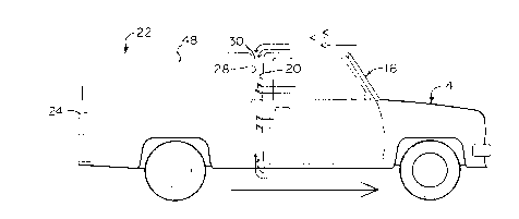
FIGURE 1 is a side elevational view of a pickup
truck with a camper cap upon its bed, showing a gap between a
cab of the pickup truck and the camper cap.
FIGURE 2 is a plan view of the instant invention
having annular ribs thereon.
,n_
CA 02245416 1998-08-24
FIGURE 3 is a cross sectional view taken along line
3-3 in Figure 2.
FIGURE 4 is a plan view of the instant invention
similar to Figure 2, without the annular ribs thereon.
FIGURE 5 is a cross sectional view taken along line
5-5 in Figure 4.
FIGURE 6 is a side elevational view similar to
Figure 1, showing the instant invention installed within the
gap.
FIGURE 7 is a rear perspective view taken in the
direction of arrow 7 in Figure 6, with parts broken away and
the camper cap in phantom, showing how the instant invention
can be installed within the gap.
-11-
CA 02245416 1998-08-24
FIGURE 8 is a cross sectional view taken along line
8-8 in Figure 6, showing the instant invention installed
within the gap about a front window in the camper cap and a
rear window in the cab of the pickup truck.
FIGURE 9 is an enlarged cross sectional view of an
area indicated by arrow 9 in Figure 8.
FIGURE l0A is a diagrammatic cross sectional view
taken along line l0A-l0A in Figure 6, showing the front
window in the camper cap and the rear window in the cab of
the pickup truck closed.
FIGURE lOB is a diagrammatic cross sectional view
taken along line lOB-lOB in Figure 6, showing the front
window in the camper cap and the rear window in the cab of
the pickup truck opened.
Similar reference characters denote corresponding
features consistently throughout the attached drawings.
-12-
CA 02245416 1998-08-24
DETAILED DESCRIPTION OF THE PREFERRED EMBODIMENTS
Turning now descriptively to the drawings, in which
similar reference characters denote similar elements
throughout the several views, Figures 2 to lOB illustrates a
truck tunnel 12. With regard to the reference numerals used,
the following numbering is used throughout the various
drawing figures.
12 truck tunnel
14 pickup truck
16 cab on 14
18 rear window in 20
-13-
CA 02245416 1998-08-24
20 rear wall of 16
22 camper cap on 24
24 bed of 14
26 front window in 28
28 front wall of 22
30 predetermined gap
32 inflatable apertured structural component
of 12
34 driver of 14
-14-
CA 02245416 1998-08-24
36 rear view mirror in 16
38 cylindrical tube for 32
40 relatively flexible, soft, resilient air
impervious material for 32
42 inflating structure of 12
44 air valve for 42 in 32
46 annular rib on 38
48 side window of 22
50 rear window of 22
-15-
CA 02245416 1998-08-24
Figure 1 shows a pickup truck 14 having a cab 16
with a rear window 18 in a rear wall 20 and a camper cap 22
on a bed 24 of the pickup truck 14 with a front window 26 in
a front wall 28, spaced by a predetermined gap 30 from the
rear wall 20 of the cab 16.
The truck tunnel 12 in Figures 2 to lOB, comprises
an inflatable apertured structural component 32 that is
insertable into the predetermined gap 30 between the rear
wall 20 of the cab 16 and the front wall 28 of the camper cap
22 and can be manipulated to extend about the rear window 18
in the rear wall 20 of the cab 16 and the front window 26 in
the front wall 28 of the camper cap 22, to form a
weatherproof and windproof seal therebetween. The rear
window l8 and the front window 26 can be left opened to allow
heated and cool air to go from the cab 16 into the camper cap
22, while greatly improving rear visibility for the driver 34
of the pickup truck 14, when looking in a rear view mirror 36
in the cab 16 through the opened rear window 18 and front
window 26.
-16-
CA 02245416 1998-08-24
The inflatable apertured structural component 32 is
a cylindrical tube 38. The inflatable apertured structural
component 32 is fabricated out of a relatively flexible,
soft, resilient air impervious material 40.
The truck tunnel 12 further contains a structure 42
for inflating the inflatable apertured structural component
32 with air. The inflating structure 42 is an air valve 44
connected to the inflatable apertured structural component
32.
The truck tunnel 12 shown in Figures 2, 3, 8 and 9, ,
can further include a plurality of annular ribs 46 integral
with and extending about opposite sides of the cylindrical
tube 38, to form a better grip and weather tight seal within
the gap 30 between the rear wall 20 in the cab 16 of the
pickup truck 14 and the front wall 28 in the camper cap 22.
The circumference of the cylindrical tube 38 is approximately
the same size as the circumference of the open rear window 18
-17-
CA 02245416 1998-08-24
in the rear wall 20 of'the cab 16 and the open front window
26 in the front wall 28 of the camper cap 22, so that the
cylindrical tube 38 can be adjusted to fit thereabout.
The cylindrical tube 38 is normally circular. When
the cylindrical tube 38 is inserted within the gap 30 between
the rear wall 20 in the cab 16 of the pickup truck 14 and the
front wall 28 in the camper cap 22 and fully inflated, the
cross sectional area of the cylindrical tube 38 will become
oval to make a tighter weatherproof and windproof seal
therebetween.
The relatively flexible, soft, resilient air
impervious material 40 in Figures 2 and 5, is shown as
rubber. The relatively flexible, soft, resilient air
impervious material 40 in Figures 8 and 9, is shown as
plastic. The camper 22 has side windows 48 and rear windows
50. The rear window 18 in the rear wall 20 of the cab 16 and
the front window 26 in the front wall 28 of the camper cap 22
-18-
CA 02245416 1998-08-24
are in alignment and can both slide open. This allows the
driver 34 of the pickup truck 14 to look into the rear view
mirror 36 past the open rear window 18 and the open front
window 26 and out through the rear windows 50 in the camper
cap, without any interference or glare. The driver 34 can
also turn to look out of one of the side windows 48, as
illustrated in Figure lOB.
-19-
CA 02245416 1998-08-24
OPERATION OF THE INVENTION
To use the truck tunnel 12, the following steps
should be taken:
1. Open the rear window 18 in the rear wall 20 of
the cab 16 on the pickup truck 14.
2. Open the front window 26 in the front wall 28
of the camper cap 22.
3. Partly inflate the cylindrical tube 38 through
the air valve 44 with an air pump.
4. Insert the partly inflated cylindrical tube 38
into the predetermined gap 30.
-20-
CA 02245416 1998-08-24
5. Manipulate the partly inflated cylindrical
tube 38, so that it extends about the opened
rear window 18 and the opened front window 26.
6. Fully inflate the cylindrical tube 38 through
the air valve 44 with the air pump, so that
the cylindrical tube 38 is securely locked
into place to prevent debris, air, wind, noise
and water from entering the gap 30, the opened
rear window 18 and the opened front window 26.
-21-
CA 02245416 1998-08-24
It will be understood that each of the elements
described above, or two or more together may also find a
useful application in other types of methods differing from
the type described above.
While certain novel features of this invention have
been shown and described are pointed out in the annexed
claims, it is not intended to be limited to the details
above, since it will be understood that various omissions,
modifications, substitutions and changes in the forms and
details of the device illustrated and in its operation can be
made by those skilled in the art without departing in any way ,
from the spirit of the present invention.
Without further analysis, the foregoing will so
fully reveal the gist of the present invention that others
can, by applying current knowledge, readily adapt it for
various applications without omitting features that, from the
standpoint of prior art, fairly constitute essential
characteristics of the generic or specific aspects of this
invention.
-22-