Language selection

Search

Patent 2245441 Summary

Third-party information liability

Some of the information on this Web page has been provided by external sources. The Government of Canada is not responsible for the accuracy, reliability or currency of the information supplied by external sources. Users wishing to rely upon this information should consult directly with the source of the information. Content provided by external sources is not subject to official languages, privacy and accessibility requirements.

Claims and Abstract availability

Any discrepancies in the text and image of the Claims and Abstract are due to differing posting times. Text of the Claims and Abstract are posted:

  • At the time the application is open to public inspection;
  • At the time of issue of the patent (grant).
(12) Patent: (11) CA 2245441
(54) English Title: SHROUD MOUNTED DOOR
(54) French Title: PORTE MONTEE SUR UNE ENVELOPPE DE RENFORT
Status: Expired and beyond the Period of Reversal
Bibliographic Data
(51) International Patent Classification (IPC):
  • D06F 37/28 (2006.01)
  • D06F 39/12 (2006.01)
  • D06F 58/20 (2006.01)
(72) Inventors :
  • DAVIES, LONNIE O., JR. (United States of America)
(73) Owners :
  • MAYTAG CORPORATION
(71) Applicants :
  • MAYTAG CORPORATION (United States of America)
(74) Agent: FINLAYSON & SINGLEHURST
(74) Associate agent:
(45) Issued: 2004-01-06
(22) Filed Date: 1998-08-21
(41) Open to Public Inspection: 1999-04-29
Examination requested: 2000-04-18
Availability of licence: N/A
Dedicated to the Public: N/A
(25) Language of filing: English

Patent Cooperation Treaty (PCT): No

(30) Application Priority Data:
Application No. Country/Territory Date
08/960,415 (United States of America) 1997-10-29

Abstracts

English Abstract


An improved laundry appliance is provided wherein
the door is mounted to a shroud, separate from the
front and top panels of the cabinet. Therefore, during
manufacturing assembly or repair work, the door can be
shut and the operation of the appliance tested with the
front and top panels removed from the appliance. After
the operational testing is completed, the front and top
panels can be installed to the remaining cabinet
panels.


French Abstract

Appareil de buanderie amélioré dans lequel la porte est montée sur une enveloppe de renfort, séparée des panneaux avant et supérieur de la carrosserie. Par conséquent, pendant la fabrication ou lors d'une réparation, on peut fermer la porte et vérifier le fonctionnement de l'appareil sans que les panneaux avant et supérieur soient en place. Une fois la vérification terminée, on peut remettre en place les panneaux avant et supérieur pour compléter l'assemblage de la carrosserie.

Claims

Note: Claims are shown in the official language in which they were submitted.

The embodiments of the invention in which an
exclusive property or privilege is claimed are defined
as follows:
1. An improved laundry appliance including a
cabinet with a rotatable tub mounted therein, and a
shroud mounted on the cabinet, the shroud having an
opening therein to provide access to the tub,
comprising:
a door pivotally mounted on the shroud for movement
between open and closed positions relative to the
shroud opening;
a panel removably mounted on the cabinet; and
the appliance being operable with the panel removed
from the cabinet.
2. The improved laundry appliance of claim 1
wherein the panel has an opening such that the panel
fits around the door.
3. The improved laundry appliance of claim 2
wherein the panel opening has a perimeter edge which
matingly surrounds the door when the door is in the
closed position.
4. The improved laundry appliance of claim 1
wherein the panel includes a substantially vertically
disposed front portion.
5. The improved laundry appliance of claim 1
wherein the panel includes a substantially horizontally
disposed top portion.

6. The improved laundry appliance of claim 1
wherein the panel includes a front portion and a top
portion.
7. The improved laundry appliance of claim 1
wherein the door pivots about a vertical axis.
8. The improved laundry appliance of claim 1
wherein the door pivots about a horizontal axis.
9. An improved laundry appliance including a
cabinet frame, opposite side panels mounted on the
frame, a rear panel mounted on the frame, a tub
rotatably mounted within the frame and having an
opening for loading and unloading laundry, and a shroud
attached to the frame and surrounding the tub opening
comprising:
a door pivotally mounted to the shroud and being
movable between open and closed positions relative
to the tub opening;
a front panel mounted to the frame;
a top panel mounted to the frame;
at least one of the front and top panels at least
partially surrounding the door and being removable
from the frame without making the appliance
inoperable.
10. The improved laundry appliance of claim 9
wherein the door is pivotally mounted along one side
edge thereof to the shroud.
11. The improved laundry appliance of claim 9
wherein the door is pivotally mounted along the bottom
edge thereof to the shroud.

Description

Note: Descriptions are shown in the official language in which they were submitted.


CA 0224~441 1998-08-21
SHROUD MOUNTED DOOR
BACKGROUND OF THE INVENTION
In conventional laundry appliances, including
front loading washing machines and dryers, the cabinet
includes opposite side panels, a rear panel, and a
front panel with a door pivotally mounted therein. In
such conventional machines, the front panel with the
door can be removed to repair internal components of
the appliance, such as the motor which rotates the tub.
However, to test the operation of the machine, either
after manufacturing assembly or after repair work, the
front panel with the door must be installed so that the
door can be closed over the access opening of the tub.
If further repair work is required, the front panel
with the door must again be removed and then
reinstalled for further operational testing. This
necessity to install or reinstall the front panel and
door prior to testing is time consuming and adds to
manufacturing and repair costs.
Therefore, a primary objective of the present
invention is the provision of an improved laundry
appliance having a door mounted separately from a
removable panel such that the operation of the
appliance can be tested without the removable panel
being installed.
Another objective of the present invention is the
provision or an improved laundry appliance wherein the
door is mounted to the shroud, separately from a
removable panel which forms a part of the appliance
cabinet.
A further objective of the present invention is
the provision of an improved laundry appliance which is
economical to manufacture, efficient and safe in use,
and quick and easy to repair.

CA 0224~441 1998-08-21
Still another objective of the present invention
is the provision of an improved laundry appliance
wherein the operation can be quickly and easily tested
while a front panel is removed.
These and other objectives of the present
invention will become apparent from the following
description of the invention.
SUMMARY OF THE INVENTION
An improved laundry appliance is provided with a
cabinet comprised of opposite side panels, a front
panel and a top panel. The front and top panels are
removable for access to the interior of the cabinet
such that assembly, repair work and operational testing
can be quickly and easily performed. The door of the
appliance is pivotally mounted to the shroud which is
mounted on the cabinet. The door remains in functional
position when the front panel is removed from the
remaining cabinet panels. Thus, the operation of the
machine can be fully tested while the front panel is
removed. In the preferred embodiment wherein the
profile of the door extends partially into the plane of
the top panel, the top panel is also removable, along
with the front panel, while allowing the door to remain
mounted so that the appliance can be operationally
tested without reinstalling the top panel and front
panel.
BRIEF DESCRIPTION OF THE DRAWINGS
Figure 1 is a perspective view of the improved
laundry appliance of the present invention with the
door closed.
Figure 2 is a perspective view of the improved
laundry appliance of the present invention with the
door open.

CA 0224~441 1998-08-21
Figure 3 is a perspective view of the appliance
with the front and top panels removed from the
remaining cabinet panels, and showing the door in the
closed position.
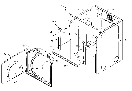
Figure 4 is an exploded perspective view of the
appliance cabinet, without the front and top panels.
Figure 5 is a partial sectional view of an
alternative embodiment wherein the door is hinged along
the bottom edge.
Figure 6 is an enlarged view taken along lines 6-6
of Figure 5.
DETAILED DESCRIPTION OF THE DRAWINGS
The improved laundry appliance of the present
invention is generally designated by the reference
numeral 10 in the drawings. The appliance includes a
cabinet 12 which comprises opposite side panels 14
mounted on internal frame members 15, a rear panel 16,
a front panel 18, and a top panel 20. Preferably, the
front panel 18 and the top panel 20 have an integral
construction with a beveled panel portion 22 extending
therebetween adjacent the upper front portion of the
cabinet 12. The front and top panels 18, 20 are
removably mounted on the frame members 15, as shown in
Figure 3.
A conventional tub 24 is mounted within the
cabinet 12, with an enlarged opening 26 providing
access to the tub for loading and unloading laundry. A
shroud 28 is mounted to the cabinet 12, via opposite
side support brackets 30, and upper bridge 32, a lower
bridge 34, and a plurality of screws or bolts 36. The
shroud 28 includes an opening 38 aligned with the
opening 26 of the tub 24. A door boot or seal 40
extends around the shroud opening 38.

CA 0224~441 1998-08-21
A door 42 is pivotally mounted to the shroud 28 by
hinges 44. The door is pivotally movable between an
open position and a closed position relative to the
shroud opening 38. The door 42 includes an inner plug
46 which sealingly engages with the door boot 40 when
the door is in the closed position.
Since the door 42 is mounted to the shroud 28,
rather than to the front panel 18, the front panel 18
and top panel 20 can be removed from the remaining
frame members 15 while the door 42 remains functionally
attached to the shroud 28. This removability of the
front and top panels 18, 20 without removal of the door
42 allows the operation of the appliance 10 to be
checked or tested before the front and top panels 18,
20 are installed. Thus, during manufacturing assembly,
or during repair work when the front panel 18 and top
panel 20 are removed for access to internal appliance
components, the door can be shut without the front and
top panels being installed so that the machine
operation can be tested. After the appliance 10 is
operating properly, either during the manufacturing or
during repair work, the front panel 18 and the top
panel 20 can be installed.
In an alternative embodiment, the door 42 is
hinged to the shroud 28 along the bottom edge of the
door by one or more hinges 48, as shown in Figures 5
and 6.
Whereas the invention has been shown and described
in connection with the preferred embodiments thereof,
it will be understood that many modifications,
substitutions, and additions may be made which are
within the intended broad scope of the following
claims. For example, in the drawings, the door is
shown to extend in the planes of both the front panel
18 and top panel 20. As an alternative, the door may

CA 02245441 1998-08-21
reside in a single plane of the front panel or top
panel.
From the foregoing, it can be seen that the
present invention accomplishes at least all of the
stated objectives.

Representative Drawing
A single figure which represents the drawing illustrating the invention.
Administrative Status

2024-08-01:As part of the Next Generation Patents (NGP) transition, the Canadian Patents Database (CPD) now contains a more detailed Event History, which replicates the Event Log of our new back-office solution.

Please note that "Inactive:" events refers to events no longer in use in our new back-office solution.

For a clearer understanding of the status of the application/patent presented on this page, the site Disclaimer , as well as the definitions for Patent , Event History , Maintenance Fee  and Payment History  should be consulted.

Event History

Description Date
Time Limit for Reversal Expired 2011-08-22
Letter Sent 2010-08-23
Inactive: IPC from MCD 2006-03-12
Grant by Issuance 2004-01-06
Inactive: Cover page published 2004-01-05
Inactive: Final fee received 2003-10-24
Pre-grant 2003-10-24
Notice of Allowance is Issued 2003-08-06
Letter Sent 2003-08-06
Notice of Allowance is Issued 2003-08-06
Inactive: Approved for allowance (AFA) 2003-07-25
Letter Sent 2000-05-10
Amendment Received - Voluntary Amendment 2000-04-27
Request for Examination Requirements Determined Compliant 2000-04-18
All Requirements for Examination Determined Compliant 2000-04-18
Request for Examination Received 2000-04-18
Inactive: Cover page published 1999-05-20
Application Published (Open to Public Inspection) 1999-04-29
Inactive: First IPC assigned 1998-11-20
Classification Modified 1998-11-20
Inactive: IPC assigned 1998-11-20
Inactive: Filing certificate - No RFE (English) 1998-10-09
Application Received - Regular National 1998-10-08

Abandonment History

There is no abandonment history.

Maintenance Fee

The last payment was received on 2003-04-16

Note : If the full payment has not been received on or before the date indicated, a further fee may be required which may be one of the following

  • the reinstatement fee;
  • the late payment fee; or
  • additional fee to reverse deemed expiry.

Patent fees are adjusted on the 1st of January every year. The amounts above are the current amounts if received by December 31 of the current year.
Please refer to the CIPO Patent Fees web page to see all current fee amounts.

Owners on Record

Note: Records showing the ownership history in alphabetical order.

Current Owners on Record
MAYTAG CORPORATION
Past Owners on Record
LONNIE O., JR. DAVIES
Past Owners that do not appear in the "Owners on Record" listing will appear in other documentation within the application.
Documents

To view selected files, please enter reCAPTCHA code :


To view images, click a link in the Document Description column. To download the documents, select one or more checkboxes in the first column and then click the "Download Selected in PDF format (Zip Archive)" or the "Download Selected as Single PDF" button.

List of published and non-published patent-specific documents on the CPD .

If you have any difficulty accessing content, you can call the Client Service Centre at 1-866-997-1936 or send them an e-mail at CIPO Client Service Centre.


Document
Description 
Date
(yyyy-mm-dd) 
Number of pages   Size of Image (KB) 
Representative drawing 1999-05-17 1 14
Representative drawing 2003-07-27 1 16
Abstract 1998-08-20 1 14
Description 1998-08-20 5 172
Claims 1998-08-20 2 61
Drawings 1998-08-20 5 107
Courtesy - Certificate of registration (related document(s)) 1998-10-12 1 114
Filing Certificate (English) 1998-10-08 1 163
Acknowledgement of Request for Examination 2000-05-09 1 178
Reminder of maintenance fee due 2000-04-25 1 111
Commissioner's Notice - Application Found Allowable 2003-08-05 1 160
Maintenance Fee Notice 2010-10-03 1 170
Correspondence 2003-10-23 1 31