Language selection

Search

Patent 2245602 Summary

Third-party information liability

Some of the information on this Web page has been provided by external sources. The Government of Canada is not responsible for the accuracy, reliability or currency of the information supplied by external sources. Users wishing to rely upon this information should consult directly with the source of the information. Content provided by external sources is not subject to official languages, privacy and accessibility requirements.

Claims and Abstract availability

Any discrepancies in the text and image of the Claims and Abstract are due to differing posting times. Text of the Claims and Abstract are posted:

  • At the time the application is open to public inspection;
  • At the time of issue of the patent (grant).
(12) Patent: (11) CA 2245602
(54) English Title: FLUID CONTROLLER
(54) French Title: REGULATEUR DE FLUIDE
Status: Expired and beyond the Period of Reversal
Bibliographic Data
(51) International Patent Classification (IPC):
  • F16K 31/122 (2006.01)
  • F16B 21/18 (2006.01)
  • F16J 01/12 (2006.01)
  • F16K 01/32 (2006.01)
(72) Inventors :
  • NISHIMURA, RYUTARO (Japan)
  • KOJIMA, TETSUYA (Japan)
(73) Owners :
  • FUJIKIN INCORPORATED
(71) Applicants :
  • FUJIKIN INCORPORATED (Japan)
(74) Agent: SMART & BIGGAR LP
(74) Associate agent:
(45) Issued: 2005-12-06
(22) Filed Date: 1998-08-25
(41) Open to Public Inspection: 1999-03-22
Examination requested: 2003-05-26
Availability of licence: N/A
Dedicated to the Public: N/A
(25) Language of filing: English

Patent Cooperation Treaty (PCT): No

(30) Application Priority Data:
Application No. Country/Territory Date
9/256578 (Japan) 1997-09-22

Abstracts

English Abstract


A ring divided in two is fitted around a valve stem
at a portion thereof projecting upward beyond a piston,
with a C-ring fitted around the divided ring. The
divided ring has an annular projection formed on its
inner periphery and fitted in an annular groove which is
formed in the valve stem at the portion thereof
projecting upward beyond the position. The divided ring
is formed in its outer periphery with an annular recess
having fitted therein the inner peripheral portion of
the C-ring.


Claims

Note: Claims are shown in the official language in which they were submitted.

10
What is claimed is:
1. A fluid controller wherein a piston connected to
an upper end of a valve stem is driven by fluid pressure
to thereby move the valve stem upward and downward and
open and close a fluid channel, the fluid controller
being characterized in that a ring divided in two is
fitted around the valve stem at a portion thereof
projecting upward beyond the piston, a C-ring being
fitted around the divided ring, the divided ring having
an annular projection formed on an inner periphery
thereof, the valve stem being formed with an annular
groove having the annular projection fitted therein, the
divided ring being formed in an outer periphery thereof
with an annular recess having fitted therein an inner
peripheral portion of the C-ring.

Description

Note: Descriptions are shown in the official language in which they were submitted.


CA 02245602 1998-08-25
1
TILE OF THE INVENTION
FLUID CONTROLLER
BACKGROUND OF THE INVENTION
The present invention relates to fluid controllers,
and more particularly to fluid controllers wherein fluid
pressure is used for moving a valve stem upward and
downward.
Fluid controllers are already known wherein a piston
attached to the upper end of a valve stem is driven by
fluid pressure to move the valve stem upward and down-
ward and thereby open and close a fluid channel. FIG. 3
shows an example of such a fluid controller, which
comprises a valve body 1, a bonnet 2 secured to the
upper end of the valve body 1, a cylinder 3 fixed to the
upper end of the bonnet 2 and having an upward opening,
a cylinder head 4 fitted over the cylinder 3, a valve
stem 5 in the form of a solid cylinder and having a
lower portion positioned in the valve body 1, an inter-
mediate portion positioned inside the bonnet 2 and an
upper portion positioned inside the cylinder 3, a valve
element 6 provided at the lower end of the valve stem 5,
a piston 7 mounted on the upper end of the valve stem 5,
an annular flange 8 secured to the intermediate portion

CA 02245602 1998-08-25
2
of the valve stem 5, and a coiled compression spring 9
bearing on the top wall of the bonnet 2 for biasing the
valve stem 5 downward.
When the fluid controller is in the usual state, the
valve stem 5 is held depressed by the elastic force of
the compression spring 9, closing a communication
passageway 12 between an inlet passageway 10 and an
outlet passageway 11. The communication passageway 12
between the passageways 10 and 11 is opened by a fluid
flowing into a cylinder chamber 14 through a working
fluid inflow passageway 13 in the cylinder 3 and pushing
up the piston 7.
The piston 7 is connected to the valve stem 5, for
example, by an E-ring 16 fitted in an annular groove 15
formed in the valve stem 5 at the portion thereof
projecting upward beyond the piston 7.
FIG. 4 shows on an enlarged scale the portion of the
piston 7 connected to the valve stem 5. The E-ring 16
comprises a C-shaped member 17, and three claws 18
integral with the inner periphery of the member and each
having an inner end fitted in the annular groove 15.
Alternatively, a U-ring 19 is used in place of the
E-ring 16. FIG. 5 shows the U-ring 19. Base portions
of bifurcated part of the ring 19 are fitted in the

CA 02245602 1998-08-25
3
annular groove 15 formed in the valve stem 5.
The E-ring 16 and the U-ring 19 have a spring
property, are fittable around the valve stem 5 when
spread out at the opening, and are prevented from
slipping off on contracting at the opening after fitting
around the stem. Thus, the piston 7 is connected to the
valve stem 5, and the fluid pressure acting on the
piston 7 is transmitted to the valve stem 5 through the
ring 16 or 19.
The conventional fluid controller has the problem
that when the piston is subjected to a pressure greater
than the prescribed pressure, a shearing force due to
the fluid pressure acting on the piston breaks the E-
ring or U-ring connecting the piston to the valve stem.
Even if it is attempted to give an increased strength to
the ring by using a different material for the ring, the
ring material is not selectable as desired because of
the limiting requirement that the ring needs to have a
spring property, consequently imposing a limitation on
the improvement of durability of the connection between
the valve stem and the piston.
SUMMARY OF THE INVENTION
An object of the present invention is to provide a
fluid controller wherein the connection between a valve

CA 02245602 1998-08-25
4
stem and a piston is given improved durability.
The present invention provides a fluid controller
wherein a piston connected to an upper end of a valve
stem is driven by fluid pressure to thereby move the
valve stem upward and downward and open and close a
fluid channel, the fluid controller being characterized
in that a ring divided in two is fitted around the valve
stem at a portion thereof projecting upward beyond the
piston, a C-ring being fitted around the divided ring,
the divided ring having an annular projection formed on
an inner periphery thereof, the valve stem being formed
with an annular groove having the annular projection
fitted therein, the divided ring being formed in an
outer periphery thereof with an annular recess having
fitted therein an inner peripheral portion of the C-
ring.
The divided ring has an inside diameter
approximately equal to the diameter of the annular
groove. The shearing stress acting on the ring is
expressed by the load on the piston divided by the
sectional area of the portion of the ring in contact
with the valve stem. The portion of the ring in contact
with the annular grooved portion of the valve stem has
an area which is approximately equal to the area of the

CA 02245602 1998-08-25
bottom of the annular groove multiplied by 0.35 to 0.45
when the ring is an E-ring, or an area which is
approximately equal to the area of the bottom of the
annular groove multiplied by 0.5 to 0.55 when the ring
5 is a U-ring. On the other hand, the area is
approximately equal to the area of the bottom of the
annular groove multiplied by 0.9 to 1.0 in the case of
the divided ring of the invention. Accordingly to the
invention, therefore, the divided ring is subjected to a
reduced shearing stress, giving an increased strength to
the connection between the valve stem and the piston.
The divided ring, which need not have a spring
property, can be made of a material having strength
against shearing forces. This affords an increased
breaking strength to the ring. This effect and also the
effect resulting from the configuration of the divided
ring further improve the durability of the connection
between the valve stem and the piston. The C-ring can
be a commercial one. The commercial C-ring is usable
when the annular recess in the outer periphery of the
divided ring is made to have a diameter in conformity
with the commercial C-ring.
BRIEF DESCRIPTION OF THE DRAWINGS
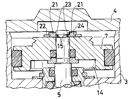
FIG. 1 is a fragmentary view in vertical section

CA 02245602 1998-08-25
6
showing a fluid controller embodying the invention;
FIG. 2 is a view in cross section of the same;
FIG. 3 is a view in vertical section showing a
conventional fluid controller;
FIG. 4 is a fragmentary view in cross section
showing the conventional fluid controller; and
FIG. 5 is a fragmentary view in cross section
showing another conventional fluid controller.
DESCRIPTION OF THE PREFERRED EMBODIMENT
An embodiment of the invention will be described
below with reference to the drawings concerned.
The present invention is embodied as a fluid
controller of the type shown in FIG. 3, wherein the
connection between the valve stem and the piston is
given improved durability. FIGS. 1 and 2 show the main
feature of the improvement.
With reference to FIGS. 1 and 2, a ring 21 divided
in two is fitted around a valve stem 5 at the portion
thereof projecting upward beyond a piston 7. A C-ring
22 is fitted around the divided ring 21.
The divided ring 21 has an annular projection 23
formed on its inner periphery and fitted in an annular
groove 15 which is formed in the valve stem 5 at the
portion thereof projecting upward beyond the piston 7.

CA 02245602 1998-08-25
7
The ring 21 is formed in its outer periphery with an
annular recess 24 having fitted therein the inner
peripheral portion of the C-ring 22.
The portion of the valve stem 5 projecting upward
beyond the piston 7 has an outside diameter of 6 mm.
The annular groove 15 is 4 mm in diameter and 0.6 mm in
width. The divided ring 21 is made of SUS303 and is 1.0
mm in overall thickness, 0.6 mm in the thickness of the
annular projection 23, 0.7 mm in the width of the
annular recess 24, 6 mm in outside diameter, 5.7 mm in
the diameter of the annular recess 24, 4.1 mm in inside
diameter and 3 mm in the diameter of the annular
projection 23. The C-ring 22 is a commercial standard
product with a nominal size of 8.
When a fluid is caused to flow into a cylinder
chamber 14 defined by a cylinder 3 and the piston 7, an
upward force acts on the piston 7 and is delivered to
the valve stem 5 through the divided ring 21. At this
time, the annular projection 23 of the ring 21 is
subjected to a great shearing force. With the structure
described above, the increase in the sectional area of
the portion of the divided ring 21 in contact with the
valve stem 5 (i.e., the annular projection 23) reduces
the shearing stress on the ring 21. The connection

CA 02245602 1998-08-25
8
between the valve stem 5 and the piston 7 is improved in
durability by this effect plus an increased strength
imparted to the divided ring 21 by using a different
material for the ring 21 and giving an increased overall
thickness to the ring 21.
Table 1 shows the result of comparison between the
fluid controller of the invention and the conventional
controllers wherein the E-ring and U-ring are used,
respectively. This table reveals that the shearing
stress in the connection between the valve stem 5 and
the piston 7 is smaller in the controller of the
invention than in the conventional ones. Consequently,
the invention gives an exceedingly higher durability
than the prior art.
Table 1
Invention E-ring U-ring
Material SUS303 SUS304 SUS304
Ring thickness 1.0 0.6 0.6
(mm)
Area of contact
0 2.11 2.91
5
with stem (mm2) .
Shearing stress 2 8.2 4.2
~
(kgf/mm2) ,
The arrangement described above is usable also in
fluid controllers other than the one shown in FIG. 3
insofar as the controllers are so adapted that a piston

CA 02245602 1998-08-25
9
provided at the upper end of a valve stem is movable
upward and downward by fluid pressure to thereby open
and close a fluid channel.

Representative Drawing
A single figure which represents the drawing illustrating the invention.
Administrative Status

2024-08-01:As part of the Next Generation Patents (NGP) transition, the Canadian Patents Database (CPD) now contains a more detailed Event History, which replicates the Event Log of our new back-office solution.

Please note that "Inactive:" events refers to events no longer in use in our new back-office solution.

For a clearer understanding of the status of the application/patent presented on this page, the site Disclaimer , as well as the definitions for Patent , Event History , Maintenance Fee  and Payment History  should be consulted.

Event History

Description Date
Time Limit for Reversal Expired 2010-08-25
Letter Sent 2009-08-25
Inactive: IPC from MCD 2006-03-12
Grant by Issuance 2005-12-06
Inactive: Cover page published 2005-12-05
Pre-grant 2005-09-20
Inactive: Final fee received 2005-09-20
Notice of Allowance is Issued 2005-06-23
Letter Sent 2005-06-23
Notice of Allowance is Issued 2005-06-23
Inactive: Approved for allowance (AFA) 2005-06-14
Letter Sent 2003-07-16
Request for Examination Requirements Determined Compliant 2003-05-26
All Requirements for Examination Determined Compliant 2003-05-26
Amendment Received - Voluntary Amendment 2003-05-26
Request for Examination Received 2003-05-26
Application Published (Open to Public Inspection) 1999-03-22
Inactive: First IPC assigned 1998-11-21
Classification Modified 1998-11-21
Inactive: IPC assigned 1998-11-21
Inactive: Filing certificate - No RFE (English) 1998-10-14
Application Received - Regular National 1998-10-13

Abandonment History

There is no abandonment history.

Maintenance Fee

The last payment was received on 2005-07-26

Note : If the full payment has not been received on or before the date indicated, a further fee may be required which may be one of the following

  • the reinstatement fee;
  • the late payment fee; or
  • additional fee to reverse deemed expiry.

Patent fees are adjusted on the 1st of January every year. The amounts above are the current amounts if received by December 31 of the current year.
Please refer to the CIPO Patent Fees web page to see all current fee amounts.

Owners on Record

Note: Records showing the ownership history in alphabetical order.

Current Owners on Record
FUJIKIN INCORPORATED
Past Owners on Record
RYUTARO NISHIMURA
TETSUYA KOJIMA
Past Owners that do not appear in the "Owners on Record" listing will appear in other documentation within the application.
Documents

To view selected files, please enter reCAPTCHA code :


To view images, click a link in the Document Description column (Temporarily unavailable). To download the documents, select one or more checkboxes in the first column and then click the "Download Selected in PDF format (Zip Archive)" or the "Download Selected as Single PDF" button.

List of published and non-published patent-specific documents on the CPD .

If you have any difficulty accessing content, you can call the Client Service Centre at 1-866-997-1936 or send them an e-mail at CIPO Client Service Centre.

({010=All Documents, 020=As Filed, 030=As Open to Public Inspection, 040=At Issuance, 050=Examination, 060=Incoming Correspondence, 070=Miscellaneous, 080=Outgoing Correspondence, 090=Payment})


Document
Description 
Date
(yyyy-mm-dd) 
Number of pages   Size of Image (KB) 
Representative drawing 1999-04-11 1 15
Description 1998-08-24 9 246
Abstract 1998-08-24 1 14
Drawings 1998-08-24 3 99
Claims 1998-08-24 1 21
Representative drawing 2005-11-09 1 20
Courtesy - Certificate of registration (related document(s)) 1998-10-13 1 114
Filing Certificate (English) 1998-10-13 1 163
Reminder of maintenance fee due 2000-04-25 1 111
Reminder - Request for Examination 2003-04-27 1 113
Acknowledgement of Request for Examination 2003-07-15 1 173
Commissioner's Notice - Application Found Allowable 2005-06-22 1 160
Maintenance Fee Notice 2009-10-05 1 170
Correspondence 2005-09-19 1 30