Language selection

Search

Patent 2245803 Summary

Third-party information liability

Some of the information on this Web page has been provided by external sources. The Government of Canada is not responsible for the accuracy, reliability or currency of the information supplied by external sources. Users wishing to rely upon this information should consult directly with the source of the information. Content provided by external sources is not subject to official languages, privacy and accessibility requirements.

Claims and Abstract availability

Any discrepancies in the text and image of the Claims and Abstract are due to differing posting times. Text of the Claims and Abstract are posted:

  • At the time the application is open to public inspection;
  • At the time of issue of the patent (grant).
(12) Patent: (11) CA 2245803
(54) English Title: IMPEDANCE REGULATOR SYSTEM AND METHOD
(54) French Title: SYSTEME ET METHODE DE REGULATION D'IMPEDANCE
Status: Expired and beyond the Period of Reversal
Bibliographic Data
(51) International Patent Classification (IPC):
  • H02J 3/16 (2006.01)
  • H02J 3/01 (2006.01)
(72) Inventors :
  • WYNN, WOODSON DALE (United States of America)
(73) Owners :
  • AT&T CORP.
(71) Applicants :
  • AT&T CORP. (United States of America)
(74) Agent: KIRBY EADES GALE BAKER
(74) Associate agent:
(45) Issued: 2000-10-31
(22) Filed Date: 1998-08-25
(41) Open to Public Inspection: 1999-03-10
Examination requested: 1998-08-25
Availability of licence: N/A
Dedicated to the Public: N/A
(25) Language of filing: English

Patent Cooperation Treaty (PCT): No

(30) Application Priority Data:
Application No. Country/Territory Date
08/929,250 (United States of America) 1997-09-10

Abstracts

English Abstract


An impedance regulator system and method which offers
a large effective high-frequency block to isolate RF signals
transmitted on power lines is presented. High-current
inductors in series are inductively coupled over the RF band
to physically smaller, low-current coupling inductors. The
coupling inductors induce a degenerative or canceling at RF
frequencies in the high-current inductors, resulting in the
effective inductor increase and hence higher impedance over
the RF band.


French Abstract

L'invention est constituée par un système et une méthode de régulation d'impédance dans lesquels un volumineux bloc haute fréquence efficace est utilisé pour protéger les signaux RF transmis sur les lignes de secteur. Des bobines en série à courant élevé sont couplées inductivement sur toute l'étendue de la bande RF à des bobines de couplage à courant faible plus petites. Ces bobines de couplage produisent un effet dégénérateur ou éliminateur aux fréquences RF dans les bobines à courant élevé, ce qui accroît l'efficacité de ces bobines et, par conséquent, l'impédance dans la bande RF.

Claims

Note: Claims are shown in the official language in which they were submitted.

WHAT IS CLAIMED IS:
1. An impedance regulator, comprising:
a first inductive element connected between a
power supply and a power sink; and
a second inductive element, inductively coupled
to the first inductive element, which degeneratively couples
to the first inductive element to reduce undesired RF noise
components on one side of the regulator relative to the noise
level on the other side of the regulator.
2. The impedance regulator according to claim 1,
wherein,
the first inductive element comprises a pair of
high-current inductors connected in series, and
the second inductive element comprises a pair of
inductors, each coupling to a corresponding one of the
high-current inductors to degeneratively couple a high-frequency
component to the high-current inductors, reducing the
high-frequency-current component in the high-current inductors.
3. The impedance regulator according to claim 2,
further comprising an amplifier connected in series between
the pair of coupling inductors.
4. The impedance regulator according to claim 3,
further comprising a high frequency-pass element connected in
series with the amplifier.
5. The impedance regulator according to claim 4,
wherein the high frequency-pass element is a capacitor.
6. The impedance regulator according to claim 5,
wherein the power supply is a 60 Hz power signal.

7. The impedance regulator according to claim 6,
wherein the first and second inductors comprise air core
coils.
8. The impedance regulator according to claim 7,
wherein the first and second inductive elements comprise
ferrite core coils.
9. The impedance regulator according to claim 8,
wherein the effective impedance presented by the impedance
regulator is increased at RF frequencies.
10. A method of regulating impedance, comprising the
steps of:
providing a first inductive element connected
between a power supply and a power sink; and
providing a second inductive element,
inductively coupled to the first inductive element, which
degeneratively couples to the first inductive element to
reduce undesired RF frequency components on the power supply
current side that arise in the power sink.
11. The method according to claim 10, wherein,
the step of providing a first inductive element
comprises the step of providing a pair of high-current
inductors connected in series, and
the step of providing a second inductive element
comprises the step of providing a pair of coupling inductors,
each coupling to a corresponding one of the high-current
inductors to degeneratively couple a high-frequency component
to the high-current inductors, reducing the
high-frequency component of current in the first inductive
element.
12. The method according to claim 11, wherein the
step of providing the second inductive element comprises the

step of providing an amplifier connected in series between
the pair of coupling inductors.
13. The method according to claim 12, wherein the
step of providing a second inductive element further
comprises the step of providing a high frequency-pass
element connected in series with the amplifier.
14. The method according to claim 13, wherein the
high frequency-pass element is a capacitor.
15. The method according to claim 14, wherein the
power supply is a 60 Hz power signal.
16. The method according to claim 15, wherein the
first and second inductors comprise air core coils.
17. The method according to claim 16, wherein the
first and second inductive elements comprise ferrite core
coils.
18. The method according to claim 17, wherein the
effective impedance provided by the impedance regulation is
increased at RF frequencies.

Description

Note: Descriptions are shown in the official language in which they were submitted.


' IMPEDANCE REGULATOR SYSTEM AND METHOD
BACKGROUND OF THE INVENTION
Field of In~ention
The invention relates to electrical regulators, and
particularly to an impedance regulator which blocks high-
frequency interference from homes and other power
destinations from interfering with RF signal transmission on
the power-line drop to the homes or other power destinations.
Description of Related Art
The modern home may be wired to receive high-
frequency information content over the power lines to the
home from transformer sources. This may be the case for ISDN
connections installed without having to use copper trunks or
without having to obtain an FCC fixed wireless license. There
are however complications in doing this, since the RF
impedance variations presented by the house load are
unpredictable and time-variable. Also, house-generated noise
on the power-line drops in the RF bands of interest can be
intense and time-dependent.
To isolate the house impedance variations and house
noise from a power line drop to the house to be used as a
transmission line for RF signals, it is known in the art to
insert high-current inductors in series in the power line at
the interface point of the outside power-line drop cables and
the house. This type of house block, 120 illustrated in FIG.
1, represents a conventional attempt to isolate the power
line drop 100 for RF signals from house impedance variations
and noise. The approach relies upon the series inductance in
the power line and a shunt capacitor across the power lines
CA 0224~803 1998-08-2~

from power mains to neutral, at the house termination of the
line drop 100.
However, these blocking techniques have the practical
problem that the passive blocking inductors must be of large
diameter wire, in order to conduct typical house currents
which are in the range of 100 amps rms. This translates to
at least 0.25 inch diameter copper wire, and a larger wire
if aluminum is used. Even using a low-~ ferrite material as
a core for such passive coils will not yield an inductance of
more than a few ~Henries for any inductor of useful size,
without saturation of the ferrite at a peak current of +
~ 100 amps.
A further problem with the realization of such
conventional blocking devices is the appearance of self-
resonant frequencies. If coil turns are closely spaced andmultiple coil layers are attempted to increase the inductance
of coils in a small physical size, the self-resonant
frequency decreases into the frequency range desired for the
signal block itself. This undesired effect is present with
air core or ferrite core coils of compact size.
SUMM~RY OF THE INVENTION
The invention overcoming these and other problems in
the prior art relates to a regulator employing an active
circuit to present an efficient, high-frequency block to
incoming power mains, while maintaining a relatively
physically small size and good resonant frequency control.
The regulator of the invention effectively presents a
degenerative RF circuit path to the incoming power line, with
the effect of increasing the inductor impedance and reducing
house generated RF noise components on the power line drop.
The regulator in the invention makes the impedance of the
CA 0224~803 1998-08-2~

power line inductance look very large to RF frequencies while
not affecting the low frequency house current flow through
the inductor.
BRIEF DESCRIPTION OF THE DRAWINGS
FIG. 1 illustrates a high-frequency current blocking
inductor of conventional passive design;
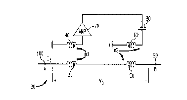
FIG. 2 illustrates an impedance regulator for high-
frequency blocking according to an illustrative embodiment of
the inventioni and
FIG. 3 illustrates a home wiring configuration in
which the impedance regulator of the invention is
illustratively employed.
DETAILED DESCRIPTION OF ~K~KK~ EMBODIMENTS
As illustrated in FIG. 2, the active regulator 20 of
the invention contains a set of components which cooperate to
reduce house generated noise on the power line drop from the
street transformer to a home or other destination. The
regulator also isolates house impedance fluctuations from the
line drop by presenting a large impedance termination that
can be shunted on the line drop side at the house by a
controlled impedance termination for the RF transmission
path.
In the regulator of the invention according to the
illustrative embodiment, a pair of high-current inductors 30
and 50 are placed in series in the house power line 90 (with
connections to inside wiring etc.) connected to the outside
power grid (also called the line drop) 100. First high-
current inductor 30 and second high-current inductor 50 have
a wire size large enough to carry the typical 100 amp rms
supply, as understood by persons skilled in the art.
Inductors 30 and 50 may be constructed with an air core, or
CA 0224~803 l998-08-2~

alternatively with ferrite cores as long as the maximum house
current does not cause core saturation which would give rise
to RF signal intermodulation components. The high-current
inductors 30 and 50 are not assumed to be magnetically
coupled, but the invention could be constructed where this
coupling does exist.
To achieve noise reduction, the invention also
provides a pair of coupling inductors 40 and 60 which are
magnetically coupled to the high-current inductors 30 and 50,
respectively. High-current inductor 30 is coupled to first
regulating inductor 40 with mutual coupling coefficient m1,
and high-current inductor 50 is coupled to second regulating
inductor 60 with coupling coefficient m2. High-current
inductor 30 couples the signal to inductor 40, which is then
amplified by amplifier 70 connected in series between
inductors 40 and 60. The resulting voltage developed across
second inductor 60 is therefore an amplified version of the
voltage across inductor 30. The voltage across inductor 30
that is coupled to inductor 40 itself is created by the
supply current I1 flowing through conductor 30.
Since one objective of the invention is to
efficiently transmit low-frequency power signals at 60 Hz, a
high-pass filter formed by capacitor 80 is connected in
series with inductor 60, to attenuate the low-frequency
components present in the regulating feedback signal.
Consequently, a voltage is induced in inductor 50 by
the reverse coupling (via m2) of inductor 60 to inductor 50.
The voltage induced in inductor 50 creates a counter-acting
(or bucking or degenerative) current to that flowing through
inductor 30. The effect of this counter-acting current
regulation is to reduce the current I1 for a given voltage V
across the series combination of inductors 30 and 50,
relative to the current that would otherwise flow in the
CA 0224~803 1998-08-2~

series connection in response to voltage V1 if inductive
degeneration was not used.
Thus, the regulator 20 of the invention has the
effect of making the apparent inductance of the series
connection of inductors 30 and 50 appear larger than the
passive value that would be presented to the RF signal band.
Blocking capacitor 80 prevents regulation at low frequencies
such as 60 Hz house current. As illustrated in FIG. 3, in a
typical home installation a pair of impedance regulators 20
according to the invention are provided in balanced fashion,
with undesired high frequency components shunted to ground
point 110 through capacitors 130. The pair of impedance
regulators of FIG. 3 are preferably enclosed in a glass or
other non-magnetic enclosure. Other numbers and
configurations of the impedance regulator 20 could be used.
Advantageously in the construction of the invention,
the physical size of the overall impedance regulator 20 is
primarily determined by the necessary coil sizes of high-
current inductors 30 and 50. Coupling inductors 40 and 60 do
not add much physical bulk to the impedance regulator 20
since these two devices can be made of very small-diameter
wire, as they only need carry higher-f~equency RF signal
currents, and not the 100-amp low-level house current. Thus,
the effective inductance seen by RF signals can be much
larger than with the passive inductance offered by the series
connection of high-current inductors 30 and 50 without
degenerative feedback, while maintaining about the same
physical size as the high-current inductors 30 and 50 alone.
The foregoing description of the impedance regulator
system and method of the invention is illustrative, and
variations in configuration and construction will occur to
persons skilled in the art. The scope of the invention is
CA 0224~803 1998-08-2~

accordingly intended to be limited only by the following
claims.
CA 02245803 1998-08-25

Representative Drawing
A single figure which represents the drawing illustrating the invention.
Administrative Status

2024-08-01:As part of the Next Generation Patents (NGP) transition, the Canadian Patents Database (CPD) now contains a more detailed Event History, which replicates the Event Log of our new back-office solution.

Please note that "Inactive:" events refers to events no longer in use in our new back-office solution.

For a clearer understanding of the status of the application/patent presented on this page, the site Disclaimer , as well as the definitions for Patent , Event History , Maintenance Fee  and Payment History  should be consulted.

Event History

Description Date
Time Limit for Reversal Expired 2002-08-26
Letter Sent 2001-08-27
Grant by Issuance 2000-10-31
Inactive: Cover page published 2000-10-30
Inactive: Final fee received 2000-07-25
Pre-grant 2000-07-25
Notice of Allowance is Issued 2000-02-24
Letter Sent 2000-02-24
Notice of Allowance is Issued 2000-02-24
Inactive: Approved for allowance (AFA) 2000-02-03
Application Published (Open to Public Inspection) 1999-03-10
Inactive: IPC assigned 1998-11-04
Inactive: First IPC assigned 1998-11-04
Inactive: IPC assigned 1998-11-04
Classification Modified 1998-11-03
Inactive: Filing certificate - RFE (English) 1998-10-14
Filing Requirements Determined Compliant 1998-10-14
Application Received - Regular National 1998-10-13
Request for Examination Requirements Determined Compliant 1998-08-25
All Requirements for Examination Determined Compliant 1998-08-25

Abandonment History

There is no abandonment history.

Maintenance Fee

The last payment was received on 2000-06-27

Note : If the full payment has not been received on or before the date indicated, a further fee may be required which may be one of the following

  • the reinstatement fee;
  • the late payment fee; or
  • additional fee to reverse deemed expiry.

Please refer to the CIPO Patent Fees web page to see all current fee amounts.

Fee History

Fee Type Anniversary Year Due Date Paid Date
Request for examination - standard 1998-08-25
Registration of a document 1998-08-25
Application fee - standard 1998-08-25
MF (application, 2nd anniv.) - standard 02 2000-08-25 2000-06-27
Final fee - standard 2000-07-25
Owners on Record

Note: Records showing the ownership history in alphabetical order.

Current Owners on Record
AT&T CORP.
Past Owners on Record
WOODSON DALE WYNN
Past Owners that do not appear in the "Owners on Record" listing will appear in other documentation within the application.
Documents

To view selected files, please enter reCAPTCHA code :


To view images, click a link in the Document Description column. To download the documents, select one or more checkboxes in the first column and then click the "Download Selected in PDF format (Zip Archive)" or the "Download Selected as Single PDF" button.

List of published and non-published patent-specific documents on the CPD .

If you have any difficulty accessing content, you can call the Client Service Centre at 1-866-997-1936 or send them an e-mail at CIPO Client Service Centre.


Document
Description 
Date
(yyyy-mm-dd) 
Number of pages   Size of Image (KB) 
Description 1998-08-25 6 217
Abstract 1998-08-25 1 15
Claims 1998-08-25 3 93
Drawings 1998-08-25 2 22
Representative drawing 1999-03-23 1 4
Representative drawing 2000-09-27 1 3
Cover Page 2000-09-27 1 36
Cover Page 1999-03-23 1 37
Courtesy - Certificate of registration (related document(s)) 1998-10-14 1 114
Filing Certificate (English) 1998-10-14 1 163
Commissioner's Notice - Application Found Allowable 2000-02-24 1 166
Reminder of maintenance fee due 2000-04-26 1 111
Maintenance Fee Notice 2001-09-24 1 179
Correspondence 2000-07-25 1 32