Language selection

Search

Patent 2245845 Summary

Third-party information liability

Some of the information on this Web page has been provided by external sources. The Government of Canada is not responsible for the accuracy, reliability or currency of the information supplied by external sources. Users wishing to rely upon this information should consult directly with the source of the information. Content provided by external sources is not subject to official languages, privacy and accessibility requirements.

Claims and Abstract availability

Any discrepancies in the text and image of the Claims and Abstract are due to differing posting times. Text of the Claims and Abstract are posted:

  • At the time the application is open to public inspection;
  • At the time of issue of the patent (grant).
(12) Patent Application: (11) CA 2245845
(54) English Title: BRACKET ASSEMBLY FOR STRAIN RELIEF OF OPTICAL FIBER JUMPERS
(54) French Title: SUPPORT DE SEPARATION ET DE REDUCTION DE TENSION POUR FILS DE CONNEXION DE CABLES OPTIQUES
Status: Deemed Abandoned and Beyond the Period of Reinstatement - Pending Response to Notice of Disregarded Communication
Bibliographic Data
(51) International Patent Classification (IPC):
  • G02B 6/44 (2006.01)
  • H04Q 1/14 (2006.01)
(72) Inventors :
  • ARIZPE, RONALD E. (United States of America)
(73) Owners :
  • SIECOR CORPORATION
(71) Applicants :
  • SIECOR CORPORATION (United States of America)
(74) Agent: GOWLING WLG (CANADA) LLP
(74) Associate agent:
(45) Issued:
(22) Filed Date: 1998-08-27
(41) Open to Public Inspection: 1999-03-02
Availability of licence: N/A
Dedicated to the Public: N/A
(25) Language of filing: English

Patent Cooperation Treaty (PCT): No

(30) Application Priority Data:
Application No. Country/Territory Date
08/922,006 (United States of America) 1997-09-02

Abstracts

English Abstract


A bracket assembly is provided for managing and strain relieving jumpers exiting an
optical hardware cabinet. The bracket has a length portion and at least one fanning finger block
mounted thereon to define a line of routing spaces for jumpers. The bracket further has at least
one tie portion located at an end of the length portion and extending laterally of the length portion
defining a free edge. The tie portion defines holes suitable for threading a cable tie therethrough.
The tie portion is located relative to the fanning finger blocks such that jumpers routed through
the fanning fingers can be gathered together over the tie portion and secured thereto with a cable
tie threaded through one of the holes. The bracket has a mounting portion extending downward
from the bracket to provide a clearance space to allow for threading of a cable tie through the
hole.


French Abstract

Cette invention concerne un support servant à séparer et à soutenir des fils de connexion sortant d'un coffret de fibres optiques. Ce support, de forme allongée, comporte au moins un peigne définissant des chemins pour les fils. Il est muni d'un moins un élément d'attache latéral situé à l'une de ses extrémités et présentant des perforations pour le passage d'un collier. La disposition de cet élément par rapport au peigne permet d'y acheminer et d'y attacher un groupe de fils au moyen d'un collier inséré dans une des perforations. Le support comporte en outre un élément de fixation formé en saillie sous sa face inférieure de manière à ménager un dégagement entre le support même et la surface de fixation pour permettre l'insertion d'un collier dans les perforations de l'élément latéral prévu à cette fin.

Claims

Note: Claims are shown in the official language in which they were submitted.

THAT WHICH IS CLAIMED IS:
1. A bracket assembly for managing and strain relieving optical fiber jumpers, comprising:
(a) - a bracket with a length portion defining a top surface extending longitudinally between a
first end and a second end and having a width between a first edge and a second edge, the bracket
having a tie portion extending laterally from the first edge at the first end to define a free edge, the
tie portion defining at least one hole adjacent the free edge defining a web between the hole and
the free edge, the hole sized to allow threading of a cable tie therethrough;
(b) at least one fanning finger block mounted on the top surface and having a plurality of
fanning fingers defining a line of routing spaces along the top surface for receiving jumpers routed
therethrough; and
(c) the hole in the tie portion being located relative to the line of routing spaces such that it
would be disposed generally underneath a jumper that is routed through the routing spaces in a
direction generally perpendicular to the length portion from the side of the bracket opposite the
tie portion and curved within minimum bend radius constraints to run parallel with the length
portion and over the tie portion.
2. The bracket assembly of Claim 1 wherein the free edge of the tie portion defines at least
one cut-out adjacent the at least one hole such that the web is defined between the hole and the
cut-out, the cut-out having a width to allow passage of a cable tie therethrough.
3. The bracket assembly of Claim 2 wherein the bracket further comprises a second tie
portion at the second end of the length portion.
Page 9

4. The bracket assembly of Claim 2 wherein the bracket further comprises mounting portions
extending downwardly from the length portion and having a foot for mounting to a surface so as
to define a clearance space underneath the tie portion.
Page 10

5. A bracket assembly for strain relieving optical fiber jumpers, comprising:
(a) a bracket having a planar tie portion having a free edge, the tie portion defining a series of
holes therethrough, each hole sized to allow threading of a cable tie therethrough, the free edge
defining a series of cut-outs adjacent the series of holes and defining a web between each hole and
its respective cut-out; and
(b) the bracket having a mounting portion extending perpendicularly from the tie portion
terminating at a free end for mounting to a suitable surface so as to define a clearance space
sufficient to allow threading of a cable tie through a hole to tie jumpers to the top of the tie
portion when the bracket is installed on the surface.
6. The bracket assembly of Claim 5 wherein the bracket further comprises a length portion
extending from the tie portion and further comprising at least one fanning finger block mounted to
the top surface defining a line of routing spaces for routing a plurality of jumpers from a direction
perpendicular to the length portion, the series of holes spaced from the at least one fanning finger
block such that the holes will be located underneath jumpers that are routed through the routing
spaces and curved within bend radius constraints to run in a direction parallel to the length
portion.
Page 11

Description

Note: Descriptions are shown in the official language in which they were submitted.


-- CA 02245845 1998-08-27 ,~_
BRACKET ASSEMBLY FOR STRAIN RELIEF OF
OPTICAL FIBER JUMPERS
FIELD OF THE INVENTION
The present invention relates to a bracket that provides for both strain relieving and
5 m~n~gin~ of optical fiber jumpers.
Page 1

--- CA 02245845 1998-08-27
BACKGROUND OF T~ INVENTION
Fiber distribution frames and wall mount cabinets are commonly used items of optical
hardware for the interconnectio~ of optical fiber jumpers with other jumpers and optical fiber
cables. One common design of optical hal dw~ t; includes connector panels that may include 6 to
5 12 connector adapters that receive optical fiber co~nectors in a mating relationship. A cabinet or
frame may include several of these panels so that anywhere up to a hundred or so jumpers may be
e~ten-ling from the hardware. These ju,l,pe,., then need to be routed to other locations. The
orderly management ofthese jumpers is needed to prevent a "rat's nest" from fol~ , on the
optical ha.~ e and allow for access and tracing of the jumpers. Optical hardware commonly
0 uses rows of fiexible fingers that define routing spaces for jumpers to aid in management of the
jumpers. However, a common drawback of some optical hardw~l~e is the lack of any strain relief
for the jumpers. Therefore a need exists for a means to provide for strain relief of optical fiber
; jumpers while still allowing for management of the jumpers. Additionally, because space is
typically at a premium in optical hardware, a need exists for the strain relieving to provided in a
5 manner that takes up minim~l space in the hardware and that is easy to use by installers of the
optic~l hardware.
Page 2

CA 0224584~ 1998-08-27 ~
SIJMMA~Y OF THE INVENTION
One aspect of the present invention provides a bracket assembly for both m~n~ging and
strain relieving optical fiber jumpers. The assembly comprises a bracket with a length portion
de.fining a top surface e~cten~ling longitll-lin~lly between a first end and a second end and having a
s width between a first edge and a second edge. The bracket has a tie portion e~t~n-ling latera!ly
from the first edge at the first end to define a free-edge. The tie portion defines at least one hole
adjacent the free edge defining a web between the hole and the free edge. The hole is sized to
allow threading of a cable tie therell~ough. The ~csemhly also has at least one fanning finger
block mounted on the top surface and has a plurality of fanning fingers defi~ing a line of routing
0 spaces along the top surface for receiving jumpers routed therethrough. The hole in the tie
portion is located relative to the line of routing spaces such that it would be disposed generally
underneath a jumper that is routed through the routing spaces in a direction generally --
perpendicular to the length portion from the side of the bracket opposite the tie portion and
curved within minimllm bend radius constraints to run parallel with the length portion and over
the tie portion.
Another aspect of the present invention provides a bracket assembly for strain relieving
optical fiber jumpers. The assembly comprises a bracket having a planar tie portion having a free
edge. The tie portion defines a series of holes therethrough and each hole is sized to allow
threading of a cable tie therethrough. The free edge defines a series of cut-outs adjacent the series
20 of holes and defines a web between each hole and its respective cut-out. The bracket also has a
mounting portion extending perpendicularly from the tie portion terminAting at a free end for
mounting to a suitable surface so as to define a clearance space sufficient to allow threading of a
Page3

- CA 02245845 1998-08-27 ,~
cable tie through one of the holes to tie jumpers to the top of the tie portion when the bracket is
installed on the sur~ace.
Page 4

-- CA 02245845 1998-08-27 ~-
BRIEF DESCRIPTION OF THE DRAWINGS
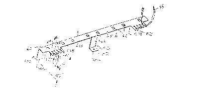
Figure 1 is a perspective view of a wall mount optical hardware cabinet cont~ining the pl~rell ed
embodiment of the bracket of the present invention; and
Figure 2 is an exploded perspective view of the prerelled embodiment of the bracket of the
5 present invention.
P~ge 5

CA 0224~84~ 1998-08-27 ~
DETAILED DESCRIPTION OF THE PREFERRED EMBODIMENTS
With reference to Figures 1-2, the preferred embodiment of bracket assembly 10 ofthe
present invention is shown. Figure 1 shows wall mount cabinet 12 as an example application for
bracket assembly 10. Cabinet 12 has housing 14 defining interior 16 where optical fibers 18 from
cables 20 are separated out, connectorized with connectors 22 and connected to first side 23 of
connector adapters 24 on adapter panels 26 that are removably mounted to side walls 28 of -
housing 14. Second side 30 of adapters 24 extend outside of housing 14 into routing channel 32
to which connectors 34 of jumpers 36 are connected. Jumpers 36 are then routed away from
panels 26 through channel 32 to another location. Door 38 closes over channel 32 to protect the
10 connections of jumpers 36 to adapters 24. Housing 14 has back side 40 that extends beyond
housing 14 and has surface 42 outside of housing 14.
Bracket assembly 10 ofthe present invention is mounted to surface 42, oriented
lon~it l~in~lly and spaced from panels 26 to be located at a point underneath where jumpers 36
will pass as they are routed from panels 26 and out channel 32 while following minimllm bend
radius requirements of optical fiber jumpers. The longitudinal extend of bracket assembly 10 is
genelally co-extensive with the longitudinal extent of the array of adapters 24.Bracket assembly 10 comprises bracket 48 with length portion 50 ~,vith first end 52 and
second end 54 opposite thereto. Length portion 50 also has top surface 56, first edge 58 and
second edge 60 Top surface defines mounting holes 62 therethrough for receiving projections 64
20 of fanning finger blocks 66 snap-fit therethrough. Fanning finger blocks 66 are known in the art
and are commonly used in optical hardware to manage the routing of jumpers One or more
blocks 66 are mounted in line along top surface 56 to define a line of routing spaces 68 between
Page 6

CA 0224~84~ 1998-08-27 ~,~
successive curved fingers 70. Bracket assembly 10 is located on surface 42 such that the line of
routing spaces 68 can receive jumpers 36 therethrough in a managed fashion.
Bracket 48 has tie portions 80 that extend from first edge 58 definin~; free edge 82
laterally removed from length portion 50 of bracket 48. Tie portions 80 are located at first end 52
and second end 54 on extend in a direction perpendicular to the length portion of bracket 48 such
that tie portions will be disposed underneath jumpers that are running generally parallel to the
length of bracket 10 after being routed through routing spaces 68 and then curved downward (or
upward) to exit channel 32.
Tie portion 80 defines line of at least one hole 84 and line of at least one cut-out 86 in free
10 edge 82. The two lines are generally parallel to each other and to the length of bracket 48 and
each hole 84 is ~djacent a respective cut-out 86 de,finin~ a web 88 between each hole and its
respective cut-out 86. Holes 84 are sized to allow threading of a common cable tie 96
therethrough. Cut-outs 86 are preferably generally u-shapes and having a width generally the
same as hole 84 to allow a cable tie 96 to be disposed through cut-out 86. Cut-outs 86 have
curved end 90 and generally straight sides 92. Curved end 90 is placed as close to hole 84 to
define a thin web 88.
In operation, jumpers 36 are routed through routing spaces 68 and curve to pass over a tie
portion 80. A cable tie is threaded through one of the holes 84 and its respective cut-out 86 and
wrapped around the jumpers and cinched closed to provide strain relief for the jumpers, With
20 web 88 as thin as appropriate without compromising its strength the circumferential cinching area
of the cable tie 96 around the jumpers is maximized, If one of the jumpers is snagged or pulled at
a point outside of cabinet 12~ the strain of such pull will be relieved at the cable tie 96 and tie
Page 7

--- CA 02245845 1998-08-27 ~
portion 80 and will not be transferred to the connectors 34 and adapters 24. More than one cable
tie 96 can be used if desired.
Cut-outs 86 are preÇ~lled because sides 92 of cut-outs 86 serve to confine the cable tie.
As an alternative embodiment, cut-outs 86 could be ~ min~ted and holes 84 moved closer to free
5 edge 82 so that the thickness of web 88 is kept to a minimnm to provide more circulllrelelllial
cinching area for the cable tie. If web 88 is too large, the ~-in-hing of the cable tie 96 is not as
effective. Web 88 is prc;~lably as small as possible while ...~ g sufficient strength of web
88 such that it will not break when a jumper is pulled or snagged inadvertently.
Bracket 48 preferably has mount portions 100 ~,xtenr~in~ d~wllw~rd from bracket 10 and
0 d~fining feet 102 with mounting holes 104 for mounting bracket assembly 10 to cabinet 12. By
having mount portions 100 extending downward, they provide for clearance space 106
underneath tie portions 80 so that when bracket 10 is mounted there is room for an installer to
thread the cable tie 96 through hole 84 and cut-out 86.
Although the present invention has been described with respect to a preferred
embodiment, it should be understood that various changes, substitutions and modifications may be
suggested to one skilled in the art and its is intended that the present invention encompass such
changes, substitutions and modifications as fall within the scope of the appended claims.
Page 8

Representative Drawing
A single figure which represents the drawing illustrating the invention.
Administrative Status

2024-08-01:As part of the Next Generation Patents (NGP) transition, the Canadian Patents Database (CPD) now contains a more detailed Event History, which replicates the Event Log of our new back-office solution.

Please note that "Inactive:" events refers to events no longer in use in our new back-office solution.

For a clearer understanding of the status of the application/patent presented on this page, the site Disclaimer , as well as the definitions for Patent , Event History , Maintenance Fee  and Payment History  should be consulted.

Event History

Description Date
Time Limit for Reversal Expired 2003-08-27
Application Not Reinstated by Deadline 2003-08-27
Deemed Abandoned - Failure to Respond to Maintenance Fee Notice 2002-08-27
Application Published (Open to Public Inspection) 1999-03-02
Inactive: IPC assigned 1998-11-09
Inactive: First IPC assigned 1998-11-09
Classification Modified 1998-11-09
Filing Requirements Determined Compliant 1998-10-16
Inactive: Filing certificate - No RFE (English) 1998-10-16
Application Received - Regular National 1998-10-13

Abandonment History

Abandonment Date Reason Reinstatement Date
2002-08-27

Maintenance Fee

The last payment was received on 2001-08-03

Note : If the full payment has not been received on or before the date indicated, a further fee may be required which may be one of the following

  • the reinstatement fee;
  • the late payment fee; or
  • additional fee to reverse deemed expiry.

Please refer to the CIPO Patent Fees web page to see all current fee amounts.

Fee History

Fee Type Anniversary Year Due Date Paid Date
Registration of a document 1998-08-27
Application fee - standard 1998-08-27
MF (application, 2nd anniv.) - standard 02 2000-08-28 2000-08-02
MF (application, 3rd anniv.) - standard 03 2001-08-27 2001-08-03
Owners on Record

Note: Records showing the ownership history in alphabetical order.

Current Owners on Record
SIECOR CORPORATION
Past Owners on Record
RONALD E. ARIZPE
Past Owners that do not appear in the "Owners on Record" listing will appear in other documentation within the application.
Documents

To view selected files, please enter reCAPTCHA code :


To view images, click a link in the Document Description column. To download the documents, select one or more checkboxes in the first column and then click the "Download Selected in PDF format (Zip Archive)" or the "Download Selected as Single PDF" button.

List of published and non-published patent-specific documents on the CPD .

If you have any difficulty accessing content, you can call the Client Service Centre at 1-866-997-1936 or send them an e-mail at CIPO Client Service Centre.


Document
Description 
Date
(yyyy-mm-dd) 
Number of pages   Size of Image (KB) 
Representative drawing 1999-03-17 1 5
Description 1998-08-27 8 220
Claims 1998-08-27 3 75
Abstract 1998-08-27 1 24
Drawings 1998-08-27 1 44
Cover Page 1999-03-17 1 50
Courtesy - Certificate of registration (related document(s)) 1998-10-16 1 114
Filing Certificate (English) 1998-10-16 1 163
Reminder of maintenance fee due 2000-05-01 1 111
Courtesy - Abandonment Letter (Maintenance Fee) 2002-09-24 1 182
Reminder - Request for Examination 2003-04-29 1 113