Note: Descriptions are shown in the official language in which they were submitted.
CA 02245919 1998-08-12
Process and Immersion Sensor for Measuring an Electrochemical Activity
The invention involves a process for measuring an electrochemical activity of
a layer
lying on a melt, using an electrochemical sensor which has a measuring cell
and a counter
electrode.
Furthermore, the invention involves an immersion sensor for measuring an
electrochemical activity of a layer lying on a melt, using an electrochemical
sensor which
is arranged on a support and has ati electrochemical measuring cell and a
counter
electrode.
A process of this type and an immersion sensor of this type are known from
Radex-
eview, Issue l, 1990, pages 23.6-243. A measuring process for measuring
electrochemical activities, especially of the oxygen content of slag layers
lying on iron
melts, is described therein. The measurement is done by a conventional
electrochemical
sensor, which has a measuring cell with zirconium oxide and magnesium oxide as
electrolytes and a counter electrode, arranged in the liquid slag layer. In
particular,
caused by non-homogenieties in the slag, the contact of the sensor with the
material to be
measured is not exactly defined, so that the measurement result cannot be
reproduced
with sufficient accuracy.
1
CA 02245919 1998-08-12
A similar sensor is described EP 330 264 Al. This sensor is used to determine
the bath
surface level, wherein the phase boundary between the metal melt and a slag
layer lying
on the metal melt is determined. A process for the indirect measurement of
electrochemical activities in slags on silver melts is described in EP 0 450
090 B 1. In this
process, an electrochemical measuring cell is arranged in a silver melt. From
the
measurement, a conclusion is made about the activity in the 'slag.
Taking the known state of the art as a starting point, the purpose of the
invention is to
provide a process of the generic type, with which reliably reproducible and
accurate
measurements are possible in the layer. Furthermore, the purpose of the
invention is to
provide an immersion sensor suited to performing the process.
According to the invention, the purpose with regard to the process is achieved
in that the
measuring cell and the counter electrode are first immersed in the melt,
wherein the
measuring cell and the counter electrode are protected from contact with the
layer, that
the measuring cell and counter electrode are brought into contact with the
melt and are
heated (to approximately the temperature of the melt), that after that the
measuring cell is
pulled up into the layer in order to perform the measurement, and that the
counter
electrode is located in the melt during the measurement. In this way, the
measurement
takes place in the mostly liquid layer, after a temperature equilibration of
the sensor to the
surrounding temperature occurs. The adjustment of the temperature is
necessary, among
other things, in order to prevent the material of the layer from solidifying
on a sensor
2
CA 02245919 1998-08-12
which is too cold. During the immersion of the sensor through the layer, the
measuring
cell and the counter electrode are protected against contact with the material
of the layer
by conventional protective covers which dissolve in the melt. The temperature
adjustment
can be monitored via the oxygen activity measurement. When an activity
plateau, which
is obtained in the melt after immersion, has been reached in the measurement
curve, the
temperature adjustment takes place. A monitoring of this adjustment is also
possible
using a thermo-element. The counter electrode is arranged in the melt during
the
measurement, i.e. in an exactly defined surrounding, making possible accurate
and easily
reproducable measurement values.
Expediently, the measuring cell and the counter electrode can be arranged on a
support,
whereby the counter electrode is simultaneously pulled up with the measuring
cell. In
this way, when the counter electrode is pulled back to the (liquid) layer, the
electrochemical activity is measured. The bath surface level of the melt can
be
determined thereby, since an abrupt change of the electrochemical activity is
measured as
soon as the counter electrode reaches the boundary layer between the melt and
the
(liquid) layer lying on it. Advantageously, the temperature of the melt and/or
the layer is
determined during measurement. It is also expedient that the measurement takes
place
during the lifting movement (the withdrawal movement) of the measuring cell
and the
counter electrode. In particular, it is also sensible to determine the oxygen
activity of the
melt prior to the withdrawal of the measuring cell from the melt. In this
manner as well,
the electrochemical activity, especially the oxygen activity of the melt and
the layer lying
3
CA 02245919 1998-08-12
on it, can be determined, and in the same measurement cycle the bath
temperature and the
bath surface level (boundary surface between the melt and the layer lying
above it) can be
determined using a single sensor, so that a separate measurement using another
sensor is
superfluous. The measurement in the melt and/or in the layer can also be
carried out
during an interruption of the lifting movement of the irnrnersion sensor,
whereby the
measuring cell and the counter electrode are located in the melt for
measurement of the
oxygen content or another electrochemical activity of the melt, while the
measuring cell
is located in the layer for measuring the oxygen content of the layer at the
same time,
wherein the counter electrode is arranged in the melt. In an advantageous way,
the
process according to the invention can be implemented for measurement in a
steel melt as
well as the slag layer lying above it. The process can also be carried out for
measurement
in liquid glass and the layers lying above it. By melt, in the context of the
invention, a
metal melt or a glass melt or liquid glass is therefore to be understood. The
determination
of the oxygen activity in a slag layer lying on a steel melt also allows
conclusions to be
made about the content of other slag components besides iron oxide. This is,
for
example, presented in detail in the prior art described above.
The purpose is achieved for an immersion sensor according to the invention in
that the
measuring cell and the counter electrode have a protective cover, and that the
measuring
cell is arranged, in the immersion position of the sensor, above the counter
electrode. A
fixed distance between the measuring cell and the counter electrode is thereby
given, and
4
CA 02245919 1998-08-12
a simultaneous movement of the measuring cell and counter electrode occurs,
such that
the distance between the two of them is kept constant.
It is expedient if the support is constructed as a support tube, and the
measuring cell is
arranged on or in the side wall of the support tube, and the counter electrode
is arranged
on the front end of the support tube. It is also advantageous if the measuring
cell is
arranged in an opening in the side wall of the support tube. In another
advantageous
embodiment the measuring Gell as well as the counter electrode are arranged on
the
immersion end of the.support tube, such that the counter electrode is arranged
on a holder
which is affixed to the immersion end of the support tube, so that its active
part has the
necessary spacing from the measuring cell. Furthermore, it is advantageous in
order to
obtain an optimal measurement result, that the longitudinal axis of the
measuring cell is
arranged perpendicular to the longitudinal axis of the support tube. As is
sufficiently
known and described in detail in the literature, measuring cells of this type
are generally
constructed as tubes which are closed on one side and made of a solid
electrolytic
material, in which the reference electrode is arranged in a reference
material.
It is further expedient if the distance between the measuring cell and the
counter electrode
(in the longitudinal direction) amounts to at least 2 cm, since by this
spacing a tolerance
range is taken into account which has the largest possible safety and results
from a
transition region between the melt and the layer lying on it. It is thereby
ensured that the
counter electrode can actually be arranged in the melt during measurement of
the layer. It
CA 02245919 2004-O1-15
is further expedient if, on the immersion end of the support a thermo-element
is arranged,
in order to determine the temperature of the melt in a simple way.
In the following, an embodiment example of the invention is explained in
greater detail
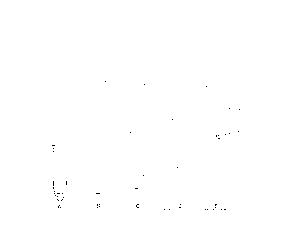
on the basis of a drawing. The drawing shows:
Fig. 1 is an immersion sensor having a measuring cell arranged on the side,
Fig. 2 is an immersion sensor having a measuring cell arranged on the front
end,
Fig. 3 is a schematic representation of the measuring process showing
different positions
of the immersion sensor, and
Fig. 4 is he progression of the electrochemical voltage during the measurement
process.
The immersion sensor depicted in Fig. 1 has a support tube l, on which an
electrochemical sensor is arranged for measurement in a slag layer above a
steel melt.
Measurement conducting lines lead from the electrochemical sensor through the
support
tube 1, and a conventional lance attached for application onto the support
tube 1, to
evaluating devices. The electrochemical sensor, which has a measuring cell 5
and a
counter electrode 4, is then protected by conventional protective covers 7
over the counter
electrode 4 and the measuring cell 5. The protective covers 7 can comprise,
for example,
CA 02245919 1998-08-12
cardboard or metal or a combination of both materials. The immersion end of
the support
tube 1 is, in addition, protected by a metal cover 8. The counter electrode 4
is arranged
on the immersion end of the support tube 1 of the sensor, while the measuring
cell 5 is
arranged several centimeters above the counter electrode 4 (in the immersion
direction).
In the surrounding area of the counter electrode 4, a thermo-element 6 is
arranged. The
counter electrode 4 can be constructed in a ring shape. The thermo-element 6
can then be
arranged inside this ring-shaped counter electrode 4, and thereby mechanically
protected
by the counter electrode 4. The thermo-element 6 measures the temperature in
the
immediate vicinity of the counter electrode 4.
Fig. 2 shows another possibility for constructing the electrochemical sensor
in which the -
measuring cell 5 and the counter electrode 4 are mounted on the immersion end
of the
support tube 1. The measuring cell 5 is surrounded by a protective cover 7,
inside of
which a thermo-element 6 is also arranged and which effects a mechanical
protection.
The counter electrode 4 has a 40 cm spacing from the measuring cell 5 and is
arranged at
the end of a holder 9, which is attached to the immersion end. In this way,
the counter
electrode 4 located at its tip has a sufficient spacing from the measuring
cell 5.: The
holder 9 can be a tube, through which the connection lines of the counter
electrode are
conducted in an insulated manner. The counter electrode 4 and the measuring
cell 5 are
thereby protected by a common protective cover 8.
7
CA 02245919 1998-08-12
It is also conceivable that the counter electrode 4 is not arranged on the
support tube l,
but instead on the crucible which contains the steel melt 3, for example, on
its bottom. In
this case, a protective cover is not necessary, since the counter electrode 4
does not come
into contact with the slag layer 2 (though the electrolyte level cannot be
determined with
this arrangement).
In order to perform the measurement, the electrochemical sensor is first
immersed
through the slag layer 2 into the steel melt 3 in such a way that both the
counter electrode
4 as well as the measuring cell 5 are arranged within the steel melt 3. When
passing
through the slag layer 2, the sensor is protected by the protective covers 7;
8 from
contacting and adhering to the slag. This condition is indicated in Fig. 3 as
position A.
In the steel melt 3 the sensor is heated, so that a temperature adjustment to
the steel melt
3 occurs. The protective covers 7; 8 are dissolved in the process (position
B). In the
position C depicted in Fig. 3, the oxygen activity (the oxygen content) of the
steel melt 3
is measured at first. After that, the electrochemical sensor is withdrawn
upwardly until
the measuring cell 5 is located above the steel melt 3 in the slag layer 2.
Here, the oxygen
activity in the slag layer 2 is measured, either during the upward movement
orrduring a
standstill of the sensor (position D).
The sensor is subsequently pulled further upwardly out of the steel melt 3. As
soon as the
counter electrode 4 also leaves the steel melt 3, i.e. enters into the
boundary layer 10
between the steel melt 3 and the slag layer 2, the voltage measured in the
measuring
s
CA 02245919 1998-08-12
process increases abruptly, so that the boundary layer 10 between the steel
melt 3 and the
slag layer 2, i.e. the bath surface level of the metal bath (steel melt 3) is
clearly shown
(position E).
The distance between the counter electrode 4 and the measuring cell 5 is
chosen to be
larger than the thickness of the boundary layer 10 between the slag layer 2
and the steel
melt 3; approximately 2 cm distance will be sufficient in some cases.
Approximately 40
cm distance has proven to be practical.
It is possible in the manner described above, to determine, one after the
other, the oxygen
content in the steel melt 3, the oxygen content in the slag layer 2, and the
surface level of -
the bath (boundary layer 10).
In Fig. 4, the voltage progression during the measurement is depicted. The
height h of
the probe is represented therein on the absissa and the measured
electrochemical voltage
U is represented on the ordinate. On the basis of the voltage, the oxygen
partial pressure
can be calculated in a generally known way. The individual positions are
indicated with
the same letters as the corresponding positions in Fig. 3. Position A shows
the voltage
when the measuring cell 5 and counter electrode 4 are immersed in the steel
melt 3, i.e. at
the beginning of measurement prior to adjustment of the temperature
equilibrium. In
position C the measuring cell 5 is located in the steel melt 3, whose oxygen
activity is
measured. In position D the measuring cell 5 is located in the slag layer 2,
while the
9
CA 02245919 1998-08-12
counter electrode 4 is arranged in the steel melt 3, so that the activity in
the slag layer 2 is
measured. Position E shows the sharp increase in the voltage when the counter
electrode
4 leaves the steel melt 3.