Note: Descriptions are shown in the official language in which they were submitted.
CA 02246064 1998-09-30
.
FUEL ASSEMBLY FOR HEAVY-WATER MODERATED NUCLEAR REACTOR
TECHNICAL FIELD
The present invention relates to a fuel assembly for
insertion into a pressure tube in a heavy-water moderated
reactor, wherein the fuel assembly is composed while using
spent fuel rods from a light-water reactor.
BACKGROUND ART
Since heavy water is a moderator with less neutron absorption
than light water, a heavy-water moderated reactor may be
operated with a lower content of fissile material than a
light-water moderated reactor. A light-water reactor requires
fuel which is enriched to a certain level. Therefore, the
possibility of using spent fuel from light-water reactors as
fuel in heavy-water moderated nuclear reactors has been
discussed. Since the reactors are composed in completely
different ways, also the fuel looks different. To be able to
use fuel from a light-water reactor in a heavy-water reactor,
the fuel must be reconstituted and adapted to the new
reactor. This is a great problem since the fuel emits high
amounts of radioactive radiation. It is preferable to handle
the spent fuel as little as possible.
A large number of different solutions have been proposed as
regards how to reconstitute the spent fuel, but these
different methods all have the above-mentioned disadvantage
of requiring a great deal of handling of the radioactive
fuel.
A heavy-water moderated reactor of a so-called CANDU type
comprises a plurality of horizontal cylindrical pressure
tubes. Each one of the pressure tubes have an inlet end into
which fresh fuel assemblies are inserted with the aid of a
CA 02246064 1998-09-30
special fuel charging/discharging machine, and an outlet end
from which burnt-out fuel assembiies emerge. A fuel assembly
has a length of about half a metre. A pressure tube at the
same time contains a plurality of fuel assemblies with
different degrees of burnup. The fuel assemblies have a
circular cross section and the fuel rods are arranged in a
polar lattice.
In a light-water reactor, the core comprises a plurality of
fuel assemblies arranged vertically in the core in a certain
spaced relationship to each other. A fuel assembly comprises
a plurality of fuel rods, each of which contains a stack of
pellets of a nuclear fuel arranged in a cladding tube. The
length of the fuel assembly corresponds to the height of the
core and is about 4 m. When the fuel is spent, the whole fuel
assembly is replaced by a fresh assembly. The fuel assembly
has a square cross section and the fuel rods are arranged in
an orthogonal lattice.
The fuel assemblies for a light-water moderated reactor and a
heavy-water moderated reactor differ from each other
primarily in that the latter is much shorter and in that they
have different lattices and different external shape.
The journal "Nuclear Europe Worldscan", No. 3-4 March-April
1997, contains on page 58 an article entitled "Progress
report on Canada/Korea/US study of PWR spent fuel in Candu".
It describes a method in which spent nuclear fuel from a
pressurized-water reactor (PWR) is reconstituted into fuel
for a heavy-water reactor. The method comprises the following
steps:
- removing the cladding on the old pellets,
- converting the old pellets by a special process into a
powder capable of being sintered,
CA 02246064 1998-09-30
- manufacturing new pellets by means of sintering of this
powder,
- inserting the pellets into new cladding tubes,
- assembling the fuel assembly, and
- taking care of old cladding and other radioactive waste for
deposition.
One of the disadvantages of this method is that it takes
about ten years before the radioactivity in the fuel has
decayed to a sufficient extent for a reconstitution of the
fuel to be carried out.
In article entitled "CANDU Fuel Cycle Flexibility" by D.F.
Torgerson, P.G. Boczar, A.R. Dastur, presented at the ninth
Pacific Basin Nuclear Conference in Sydney, Australia, 1994
May 1-6, the possibility is mentioned of reconstituting fuel
rods from PWR reactors by first shortening them and then
assembling a fuel assembly adapted for a heavy-water reactor
with the shortened fuel rods. In this way, it is not
necessary to manufacture new pellets from the used fuel. A
problem in this connection is how to achieve a tight cladding
around the shortened fuel rod in a simple manner. A solution
which is mentioned comprises inserting the shortened rod into
a new cladding tube which is then sealed at the ends with new
end plugs. This results in the fuel rod having double
cladding tubes, which leads to a deteriorated heat transfer
between the fuel and the coolant, and increased neutron
absorption.
Common to these solutions is that they are based on PWR fuel
assemblies which have fuel rods, the length of which
corresponds to the length of the fuel assemblies. One of the
problems which arises is that the fuel rods are too long to
fit in a heavy-water reactor.
CA 02246064 1998-09-30
Patent document PCT/SE95/01478 shows a fuel assembly for a
boiling water reactor (BWR) which comprises a plurality of
fuel units, stacked on top of each other, each of which
comprising a plurality of fuel rods extending between a top
5 tie plate and a bottom tie plate. The fuel units are
surrounded by a common fuel channel with a substantially
square cross section.
PCT/SE97/01082 (WO 97/49098) shows a fuel assembly for a PWR,
10 which also comprises a plurality of fuel units stacked on top
of each other, each one comprising a plurality of fuel rods
extending between a top nozzle and a bottom nozzle.
SU~ARY OF THE INVENTION
The invention aims to provide a method for rapidly and simply
reconstituting spent nuclear fuel from a light-water reactor
to a fuel assembly for a heavy-water reactor.
20 The invention also aims to provide a fuel assembly intended
for use in a heavy-water reactor which comprises a plurality
of spent fuel rods from a light-water reactor.
What characterizes a method and a fuel assembly according to
25 the invention will become clear from the appended claims.
According to the invention, the starting-point are fuel rods
which have been included in a fuel assembly which is composed
of a plurality of short fuel units. In this way, the problem
30 of having to shorten fuel rods is avoided.
BRIEF DESCRIPTION OF THE DRAWINGS
Figure 1 shows a known fuel assembly for a boiling water
35 reactor moderated by light water.
CA 02246064 1998-09-30
Flgure 2 shows a section A-A through the fuel assembly in
Figure 1.
Figure 3 shows a fuel assembly for a heavy-water moderated
nuclear reactor according to a first embodiment of the
invention.
Figure 4 shows a fuel assembly for a heavy-water moderated
nuclear reactor according to a second embodiment of the
invention.
Figures 5 and 6 show in a section B-B through the fuel
assembly in Figure 3 two different lattice configurations for
the fuel rods.
Figure 7 shows a fuel assembly for a heavy-water moderated
nuclear reactor according to a third embodiment of the
invention.
Figure 8 shows a fuel assembly for a heavy-water moderated
nuclear reactor according to a fourth embodiment of the
invention.
Figure 9 shows a section C-C through the fuel assembly in
Figure 7.
Figure 10 shows a section D-D through the fuel assembly in
Figure 8.
Figures 11-13 show additional lattice configurations for the
fuel rods.
DESCRIPTION OF THE PREFERRED EMBODIMENTS
Figure 1 shows a known fuel assembly for a boiling water
reactor moderated by light water (BWR). The fuel assembly
CA 02246064 1998-09-30
comprises an upper handle 1, a lower end portion 2 and a
plurality of fuel units 3 stacked on top of each other. Each
fuel unit comprises a plurality of fuel rods 4 arranged in
parallel and in a definite space relationship to each other
in a given lattice, and a top tie plate 5 and a bottom tie
plate 6 for attachment of the fuel rods in their respective
positions in the lattice. The fuel units 3 are stacked on top
of each other in the longitudinal direction of the fuel
assembly and they are stacked in such a way that the top tie
plate 5 in one fuel unit is facing the bottom tie plate 6 in
the next fuel unit in the stack, and such that the fuel rods
in all the fuel elements are parallel to each other. A fuel
rod 4 comprises fuel in the form of a stack of pellets 7 of
uranium arranged in a cladding tube 10.
Figure 2 shows a section A-A through the fuel assembly in
Figure 1. The fuel units are enclosed in a fuel channel 8
with a substantially s~uare cross section. The fuel channel
is provided with a support member 9 of cruciform cross
section which is secured to the four walls of the fuel
channel. The fuel channel with the support member surrounds
four vertical channel-formed parts 11, so-called sub-
channels, with an at least substantially square cross
section. The four sub-channels each contain a stack of fuel
units. Each fuel unit comprises 24 fuel rods 4 arranged in a
symmetrical 5x5 lattice.
According to the invention, a heavy-water moderated fuel
assembly is composed of fuel rods from burnt-out fuel units,
for example those shown in Figures 1 and 2. One of the
problems which have to be solved when using fuel rods from
light-water reactors in a fuel assembly for a heavy-water
reactor is how to design the fuel assembly for guiding
towards the pressure tube and for support between the rods.
In a fuel assembly for a heavy-water reactor, each fuel rod
is provided with a number of support pads for these purposes.
CA 02246064 1998-09-30
No such pads are provided on light-water fuel rods.
Admittedly, it is possible to add pads to the spent light-
water fuel, but because of the radioactive radiation, it is
preferable to avoid this.
In one embodiment of the invention, the fuel unit is
dismantled by removing the bottom tie plate and the top tie
plate from the fuel rods. The end surfaces of the fuel rods
are prepared for new welding. Thereafter, the fuel rods are
arranged in a new lattice configuration and new end plates,
intended for the heavy-water reactor, are welded on.
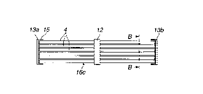
Figure 3 shows a fuel assembly for a heavy-water moderated
reactor in which all the fuel rods 4 originate from the BWR
units 3 in Figure 1. In this embodiment, the fuel rods in the
fuel units have a length corresponding to the length of a
heavy-water fuel assembly, that is, about 0.5 m. The fuel
assembly comprises a fuel unit 16c which comprises a
plurality of BWR fuel rods 4 arranged in parallel with each
other between two end plates 13a and 13b. The end plates are
provided with support surfaces 15 for guiding towards the
pressure tube. To keep the fuel rods spaced apart from each
other and provide support for the fuel rods, a spacer 12 is
arranged between the end plates. The spacer is designed so as
also to function as support against the pressure tube. Thus,
such a fuel assembly have three support surfaces against the
pressure tube, two on the end plates and one on the spacer.
This is sufficient to guide the assembly towards the pressure
tube.
Figure 4 also shows a fuel assembly for a heavy-water
moderated reactor in which all the fuel rods 4 ori~inate from
the fuel units 3 in Figure 1. In this embodiment, the fuel
rods in the fuel units have a length corresponding to half
the length of a heavy-water fuel assembly, that is, about
0.25 m. The fuel assembly comprises two fuel units 16a and
CA 02246064 1998-09-30
16b, each of which comprises a plurality of spent BWR fuel
rods 4 arranged between two end plates 14a, 14b, 14c and 14d.
The two fuel units 16a, 16b are joined into a fuel assembly.
The joining of the fuel units takes place by welding together
two end plates. All the end plates are provided with support
surfaces 15 for guiding towards the pressure tube.
It is also possible to start from a BWR fuel with a rod
length different from that of the above example, if only
these together result in the same core length and the fuel
discharging machine may be adapted thereto.
Figures 5 and 6 show two feasible lattice configurations for
the fuel assemblies shown in Figures 3 and 4. Since BWR fuel
rods are normally thinner than fuel rods intended for heavy-
water reactors, a larger number of fuel rods are required in
a fuel assembly with recycled BWR fuel than in a fuel
assembly with fresh fuel. Figure 5 shows a fuel assembly with
52 fuel rods arranged in an orthogonal lattice. An advantage
of such a lattice is that a spacer for intermediate support
may be designed in accordance with well-known BWR technology.
Figure 6 shows a fuel assembly with 55 fuel rods arranged in
a polar lattice.
Figures 7 and 8 show two embodiments of a fuel assembly
according to the invention which comprises both spent BWR
fuel rods 4 and fresh fuel rods 23, 24 intended for a heavy-
water reactor. The spent fuel rods are arranged in the
central part of the fuel assembly and the fresh ones are
arranged in the peripheral part of the fuel assembly. The
fresh fuel rods are provided with support pads 17 for
supporting against the pressure tube and adjacent fuel rods.
Figure 7 shows a fuel assembly in which the spent fuel rods 4
have a length which is equal to the length of the fuel
assembly. The fuel assembly has two end plates 18. These need
CA 02246064 1998-09-30
not be provided with support surfaces as in the preceding
example since the outer fuel rods are provided with support
pads. Figure 9 shows a section through the fuel assembly in
Figure 7. The fuel assembly contains 28 BWR fuel rods 4, the
diameter of which is 9 mm and 32 fresh heavy-water fuel rods
23, the diameter of which is 10 mm. The fuel assembly has a
diameter which is 102 mm.
In another embodiment of the invention, the fuel unit is not
dismantled, but instead the whole fuel unit is used as it is.
The fuel unit is thus allowed to retain its original lattice
configuration and its BWR end plates. A fuel assembly for a
heavy-water reactor is composed by mounting fresh heavy-water
fuel 24 around the BWR fuel unit.
PCT/SE97/02020 (WO 98/28753) shows a fuel assembly for a
boiling water reactor which comprises a plurality of short
fuel units stacked on top of each other. The fuel units have
fuel rods arranged in a polar lattice between two end plates.
Such a fuel unit already has a lattice which is suitable for
a heavy-water reactor and according to one embodiment of the
invention, it is reconstructed into a fuel assembly for a
heavy-water reactor without being dismantled. Fresh fuel rods
are mounted around the fuel unit and new end plates are
welded together with the old BWR end plates to keep the fresh
fuel in position.
Figure 8 shows two such BWR fuel units 21 and 22 which are
joined to each other. The fuel units together have a length
which corresponds to the length of a heavy-water fuel rod 23.
The BWR end plates 19 are joined to new annular end plates
20. Before the end plates are welded together, an adjustment
of the outer contours of the BWR end plates takes place.
- 35 Figure 10 shows a section through the fuel assembly which is
shown in Figure 8. The BWR fuel units contain 28 fuel rods 4,
CA 02246064 1998-09-30
the diameter of which is 9 mm and they are surrounded by 16
fresh heavy-water rods 24 with a diameter which is 14 mm. The
diameter of the fuel assembly is 102 mm.
Figures 11, 12 och 13 show three different embodiments
wherein a BWR fuel unit 30 with an orthogonal lattice has
been rebuilt into a fuel assembly for a heavy-water reactor.
The fuel unit 30 is not dismantled but the whole unit is used
as it is. The BWR fuel unit contains 24 fuel rods 26, the
diameter of which is 10 mm.
In Figure 11 the fuel unit is surrounded by 12 fresh heavy-
water rods 27, the diameter of which is 13 mm and 9 heavy-
water rods 28, the diameter of which is 10 mm. In Figure 12
the fuel unit is surrounded by 16 fresh heavy-water rods, the
diameter of which is 13 mm. In Figure 13 the fuel unit is
surrounded by 12 fresh heavy-water rods 29, the diameter of
which is 14 mm, plus any completion of fuel rod in the
oblique corner.
The embodiments shown above are based on fuel assemblies for
boiling water reactors. PCT/SE97/01082 (WO 97/49098) shows a
fuel assembly for a PWR which also comprises a plurality of
short fuel units stacked on top of each other, each fuel unit
comprising a plurality of fuel rods extending between a top
tie plate and a bottom tie plate. The invention is, of
course, also applicable to short fuel units intended for a
pressurized-water reactor.
One condition for the invention is that the length of the
fuel rods in the light-water fuel assembly has been chosen
such that they may be used in a heavy-water reactor without
having to open and modify the fuel rods.