Language selection

Search

Patent 2246096 Summary

Third-party information liability

Some of the information on this Web page has been provided by external sources. The Government of Canada is not responsible for the accuracy, reliability or currency of the information supplied by external sources. Users wishing to rely upon this information should consult directly with the source of the information. Content provided by external sources is not subject to official languages, privacy and accessibility requirements.

Claims and Abstract availability

Any discrepancies in the text and image of the Claims and Abstract are due to differing posting times. Text of the Claims and Abstract are posted:

  • At the time the application is open to public inspection;
  • At the time of issue of the patent (grant).
(12) Patent: (11) CA 2246096
(54) English Title: ROOF CURB
(54) French Title: OUVRAGE VERTICAL DE TOITURE
Status: Term Expired - Post Grant Beyond Limit
Bibliographic Data
(51) International Patent Classification (IPC):
  • E04B 07/18 (2006.01)
  • E04D 13/03 (2006.01)
  • E04D 13/147 (2006.01)
  • F24F 13/32 (2006.01)
(72) Inventors :
  • MCCLURE, RICHARD R. (United States of America)
(73) Owners :
  • BLUESCOPE BUILDINGS NORTH AMERICA, INC.
(71) Applicants :
  • BLUESCOPE BUILDINGS NORTH AMERICA, INC. (United States of America)
(74) Agent: MARKS & CLERK
(74) Associate agent:
(45) Issued: 2005-07-26
(22) Filed Date: 1998-08-28
(41) Open to Public Inspection: 1999-02-28
Examination requested: 1999-07-29
Availability of licence: N/A
Dedicated to the Public: N/A
(25) Language of filing: English

Patent Cooperation Treaty (PCT): No

(30) Application Priority Data:
Application No. Country/Territory Date
08/920,895 (United States of America) 1997-08-29

Abstracts

English Abstract

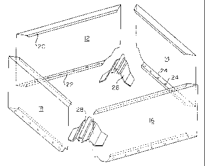
A rectangular curb unit is installed on a sloping standing seam metal roof at an angle to the dip direction, so that water does not accumulate on the upslope side of the curb unit. The curb unit has four side walls, and inserts shaped to conform to the seam geometry are welded to the walls at the seam locations, typically at opposite corners.


French Abstract

Une unité de rebord rectangulaire est installée sur un toit de tôle à joint debout en pente ayant un angle dans le sens de l'inclinaison, afin que l'eau ne s'accumule pas du côté ascendant de l'unité de rebord. L'unité de rebord a quatre parois latérales, et des inserts formés pour s'adapter à la géométrie du joint sont soudés aux murs aux emplacements du joint, généralement à des angles opposés.

Claims

Note: Claims are shown in the official language in which they were submitted.


I claim as my invention:
1. In combination with a sloping roof made of metal panels
joined by seams running substantially in a downslope direction, a
curb unit comprising:
four side walls interconnected to form a rectangle,
said curb unit being mounted diagonally on the roof,
with every side wall non-perpendicular to the
downslope direction, and
two inserts one at each of diagonally opposite corners
of the rectangle, each insert having a bottom surface
conforming to a profile of one of said seams, and the
side walls adjacent the inserts conforming to the seam
profile.
2. The curb unit of claim 1, wherein each insert is an
aluminum extrusion having a length and being cut at one end by
two perpendicular planes which intersect along a line
perpendicular to the length of the extrusion.
3. The curb unit of claim 2, wherein the four side walls are
of equal length, and each of said planes is at an angle of 45° to
the length of the extrusion.
4. A method of installing a rectangular curb unit on a standing
seam metal sloped roof having a dip direction, said curb unit
having four side walls forming an inner perimeter, each wall
having a bottom, said method comprising steps of:
placing the curb unit on the roof, with every side non-
perpendicular to the dip direction,
marking lines on the roof along the inner perimeter of the
4

curb unit,
temporarily removing the curb unit from the roof,
cutting a hole in the roof along said lines,
applying sealant around the hole in the roof,
replace the curb unit on the roof and securing it by
driving fasteners through flanges on the curb unit and into the
roof.
5. The method of claim 4, further comprising a step of cutting
existing roof insulation below the hole, drawing exposed edges
of the insulation upward, and clamping them against the bottom
of each side wall by fastening a metal strip to the side wall
over the insulation.
6. The method of claim 4, wherein the curb unit is square, and
each side is installed at an angle of 45° to the dip direction.

Description

Note: Descriptions are shown in the official language in which they were submitted.


CA 02246096 2004-02-06
BACKGROUND OF THE INVENTION
This invention relates to metal roof construction.
Curbs are constructed on metal roofs around skylights and
mechanical equipment such as heating or air condition units, to
divert rain precipitation around the unit. The curbs are usually
constructed as a rectangle whose side walls are parallel to
corresponding sides of the roof. Where the roof has a slope,
normally the upslope and downslope curbs are perpendicular to the
dip of the roof. As a result, water tends to collect along the
upslope curb, and may leak past the curb or cause premature
corrosion. U.S. Patents No. 4,413,450, No. 5,522,189 and No.
5,027,576 are representative of prior curbs, installed
orthogonally on a roof so that the upslope curb is perpendicular
to the dip of the roof.
SUMMARY OF THE INVENTION
It is an object of an aspect of this invention to prevent
water from collecting against a curb installed on a sloped roof.
I have realized that a rectangular curb unit can be
installed diagonally on a sloped roof to prevent water from
collecting along any side wall.
Therefore, various aspects of the invention are provided as
follows:
In combination with a sloping roof made of metal
panels joined by seams running substantially in a downslope
direction, a curb unit comprising:
four side walls interconnected to form a rectangle,
said curb unit being mounted diagonally on the roof,
with every side wall non-perpendicular to the
downslope direction, and
two inserts one at each of diagonally opposite corners
of the rectangle, each insert having a bottom surface
conforming to a profile of one of said seams, and the side
1

CA 02246096 2004-09-22
walls adjacent the inserts conforming to the seam
profile.
A method of installing a rectangular curb unit on a
standing seam metal sloped roof having a dip direction, said
curb unit having four side walls forming an inner perimeter,
each wall having a bottom, said method comprising steps of:
placing the curb unit on the roof, with every side
non-perpendicular to the dip direction,
marking lines on the roof along the inner perimeter of the
curb unit, temporarily removing the curb unit from the roof,
cutting a hole in the roof along said lines,
applying sealant around the hole in the roof,
replace the curb unit on the roof and securing
it by driving fasteners through flanges on the curb unit and
into the roof.
A detailed description of how this may be accomplished
follows.
BRIEF DESCRIPTION OF THE DRAWINGS
In the accompanying drawings,
Figure 1 is an exploded perspective view of a curb unit
embodying the invention;
Figure 2 is a corresponding view of the curb unit, assembled;
Figure 3 shows a worker marking the intended location for the
curb on a standing seam roof;
Figure 4 shows a hole which has been cut in the .roof, and
reinforced;
Figure 5 shows weather seal being applied around the hole;
1a

' CA 02246096 2004-02-06
Figure 6 shows the curb being installed over the hole;
Figure 7 shows insulation being applied to the curb unit;
Figure 8 shows final weather sealing being applied; and
Figure 9 is a sectional view taken on the plane 9-9 in Fig.
8.
DESCRIPTION OF THE PREFERRED EMBODIMENTS
As shown in Figure 1, a square curb unit 10 embodying the
invention comprises four side walls 12, 14, 16 and 18 of equal
length and height. The top flange of each is turned down at 20,
and the lower flange is turned up at 22. The lower flange is
punctuated by a series of bolt holes 24. Items 26 and 28 are
inserts shaped to conform to the profile of the corrugations on
the metal roof for which the curb unit 10 is intended.
The inserts are, preferably, cut from aluminum extrusions.
Those illustrated are intended for use on an MR-24 roof (Butler
Manufacturing Company, Kansas City, Missouri). The cross-
sectional shape is seen at the cut end of the extrusion, near the
numeral 26 in Figure 1. It includes a central arch intended to
just clear a crimped seam between adjacent roof panels, and wings
on either side of the arch, each having an inverted "gull wing"
profile corresponding to the MR-24 roof's corrugations. The inner
end of the insert is cut straight across, while the outer end is
cut on two perpendicular planes corresponding to the planes of
the side walls, such that the planes are at an angle of 45° to
the length of the extrusion. The adjacent bottom corners of the
sides are cut to conform to the shape of the bottom edge of each
insert.
The unit is assembled by welding the corners 30 to form the
finished unit 10 shown in Figure 2. Assembly is preferably done
in a factory with precision fixtures, but the curb unit 10 could
be built up at the work site if necessary.
Figure 3 shows a worker on the roof marking the roof "R"
along the inner perimeter of the curb unit 10, where the unit 10
is to be installed over a seamed corrugation "C" between
supporting purlins "P". Then, the unit 10 is temporarily removed,
and a hole is cut through the roof along the line marked.
Reinforcing channels 34 are then attached below the roof
2

CA 02246096 2004-02-06
panels, one wing of each channel lining the hole to reinforce
the roof and to receive fasteners. After weather sealant (e. g.,
tape 36 and/or caulking 38, Fig. 5) has been applied to the
perimeter of the hole, the curb unit 10 is replaced (Fig. 6)
and secured by inserting self-tapping bolts 40 through the
holes 24 in the bottom flanges of the side walls, then driving
them through the roof panels into the reinforcing channels 34.
To complete the installation, the existing roof insulation 46
(Fig. 9) is cut as in Fig. 7, and drawn upward; the loose edges
are bound by fastening trim strips 42 to the bottom flange 22
with screws 44. The volume of the side wall may be filled with
insulation 48. The joint between the roof and curb unit 10 is
caulked (Fig. 8), and a gasket 50 may be applied to the top
flange of the curb unit 10 if a closure is to be installed.
Inasmuch as the invention is subject to variations and
modifications, it is intended that the drawings and the
foregoing description shall be interpreted as merely
illustrative of the invention defined by the claims that
follow.
3

Representative Drawing
A single figure which represents the drawing illustrating the invention.
Administrative Status

2024-08-01:As part of the Next Generation Patents (NGP) transition, the Canadian Patents Database (CPD) now contains a more detailed Event History, which replicates the Event Log of our new back-office solution.

Please note that "Inactive:" events refers to events no longer in use in our new back-office solution.

For a clearer understanding of the status of the application/patent presented on this page, the site Disclaimer , as well as the definitions for Patent , Event History , Maintenance Fee  and Payment History  should be consulted.

Event History

Description Date
Inactive: Expired (new Act pat) 2018-08-28
Letter Sent 2009-05-13
Inactive: IPC from MCD 2006-03-12
Grant by Issuance 2005-07-26
Inactive: Cover page published 2005-07-25
Pre-grant 2005-05-02
Inactive: Final fee received 2005-05-02
Notice of Allowance is Issued 2004-12-01
Letter Sent 2004-12-01
Notice of Allowance is Issued 2004-12-01
Inactive: Approved for allowance (AFA) 2004-11-19
Amendment Received - Voluntary Amendment 2004-09-22
Inactive: S.30(2) Rules - Examiner requisition 2004-03-24
Amendment Received - Voluntary Amendment 2004-02-06
Inactive: S.30(2) Rules - Examiner requisition 2003-08-08
Letter Sent 1999-11-15
Inactive: Single transfer 1999-10-21
Inactive: Adhoc Request Documented 1999-10-21
Amendment Received - Voluntary Amendment 1999-09-21
Letter Sent 1999-08-17
All Requirements for Examination Determined Compliant 1999-07-29
Request for Examination Requirements Determined Compliant 1999-07-29
Request for Examination Received 1999-07-29
Application Published (Open to Public Inspection) 1999-02-28
Inactive: Filing certificate - No RFE (English) 1999-02-05
Inactive: First IPC assigned 1998-11-27
Classification Modified 1998-11-27
Inactive: IPC assigned 1998-11-27
Inactive: Correspondence - Formalities 1998-11-19
Inactive: Filing certificate - No RFE (English) 1998-10-15
Application Received - Regular National 1998-10-14

Abandonment History

There is no abandonment history.

Maintenance Fee

The last payment was received on 2005-04-15

Note : If the full payment has not been received on or before the date indicated, a further fee may be required which may be one of the following

  • the reinstatement fee;
  • the late payment fee; or
  • additional fee to reverse deemed expiry.

Patent fees are adjusted on the 1st of January every year. The amounts above are the current amounts if received by December 31 of the current year.
Please refer to the CIPO Patent Fees web page to see all current fee amounts.

Owners on Record

Note: Records showing the ownership history in alphabetical order.

Current Owners on Record
BLUESCOPE BUILDINGS NORTH AMERICA, INC.
Past Owners on Record
RICHARD R. MCCLURE
Past Owners that do not appear in the "Owners on Record" listing will appear in other documentation within the application.
Documents

To view selected files, please enter reCAPTCHA code :


To view images, click a link in the Document Description column. To download the documents, select one or more checkboxes in the first column and then click the "Download Selected in PDF format (Zip Archive)" or the "Download Selected as Single PDF" button.

List of published and non-published patent-specific documents on the CPD .

If you have any difficulty accessing content, you can call the Client Service Centre at 1-866-997-1936 or send them an e-mail at CIPO Client Service Centre.


Document
Description 
Date
(yyyy-mm-dd) 
Number of pages   Size of Image (KB) 
Representative drawing 1999-03-08 1 10
Abstract 1998-08-27 1 13
Claims 1998-08-27 2 53
Description 1998-08-27 3 128
Drawings 1998-08-27 5 108
Description 1999-09-20 4 147
Description 1998-11-18 3 124
Claims 1998-11-18 2 50
Abstract 1998-11-18 1 11
Drawings 1998-11-18 5 107
Description 2004-02-05 4 138
Claims 2004-02-05 2 45
Drawings 2004-02-05 5 107
Description 2004-09-21 4 140
Claims 2004-09-21 2 47
Representative drawing 2005-07-12 1 14
Filing Certificate (English) 1998-10-14 1 163
Filing Certificate (English) 1999-02-04 1 163
Acknowledgement of Request for Examination 1999-08-16 1 193
Request for evidence or missing transfer 1999-08-30 1 113
Courtesy - Certificate of registration (related document(s)) 1999-11-14 1 115
Reminder of maintenance fee due 2000-04-30 1 111
Commissioner's Notice - Application Found Allowable 2004-11-30 1 162
Correspondence 1998-10-19 1 40
Correspondence 1998-11-18 2 69
Correspondence 1998-11-18 12 319
Fees 2003-07-14 1 48
Fees 2002-04-09 1 49
Fees 2001-06-10 1 49
Fees 2004-08-17 1 46
Correspondence 2005-05-01 1 49
Fees 2005-04-14 1 55
Fees 2006-04-26 1 49
Fees 2007-07-09 1 52
Fees 2008-08-06 1 57
Fees 2009-08-04 1 62