Language selection

Search

Patent 2246177 Summary

Third-party information liability

Some of the information on this Web page has been provided by external sources. The Government of Canada is not responsible for the accuracy, reliability or currency of the information supplied by external sources. Users wishing to rely upon this information should consult directly with the source of the information. Content provided by external sources is not subject to official languages, privacy and accessibility requirements.

Claims and Abstract availability

Any discrepancies in the text and image of the Claims and Abstract are due to differing posting times. Text of the Claims and Abstract are posted:

  • At the time the application is open to public inspection;
  • At the time of issue of the patent (grant).
(12) Patent Application: (11) CA 2246177
(54) English Title: ELECTRICAL GROUNDING CONNECTOR WITH COMPRESSION CONDUCTOR CONNECTOR
(54) French Title: CONNECTEUR DE MISE A LA TERRE AVEC CONNECTEUR A COMPRESSION
Status: Deemed Abandoned and Beyond the Period of Reinstatement - Pending Response to Notice of Disregarded Communication
Bibliographic Data
(51) International Patent Classification (IPC):
  • H01R 04/64 (2006.01)
  • H01R 04/48 (2006.01)
  • H01R 04/60 (2006.01)
  • H01R 04/66 (2006.01)
(72) Inventors :
  • ZWIT, ANDREW T. (United States of America)
(73) Owners :
  • FRAMATOME CONNECTORS INTERNATIONAL
  • FRAMATOME CONNECTORS INTERNATIONAL
(71) Applicants :
  • FRAMATOME CONNECTORS INTERNATIONAL (France)
  • FRAMATOME CONNECTORS INTERNATIONAL (France)
(74) Agent: BKP GP
(74) Associate agent:
(45) Issued:
(22) Filed Date: 1998-08-28
(41) Open to Public Inspection: 1999-03-09
Examination requested: 2002-06-12
Availability of licence: N/A
Dedicated to the Public: N/A
(25) Language of filing: English

Patent Cooperation Treaty (PCT): No

(30) Application Priority Data:
Application No. Country/Territory Date
08/926,364 (United States of America) 1997-09-09

Abstracts

English Abstract


An electrical grounding connector for connecting a
conductor to a pipe. The connector comprises a band and
an electrical compression connector. The band wraps
around the pipe and has two ends that form an outwardly
extending stem. The compression connector has two
apertures. The compression connector is mounted to the
band with the stem in a first one of the apertures. A
conductor is received in the second aperture. The
compression connector is compressed onto the stem and the
conductor at the same time.


French Abstract

La présente invention a pour objet un connecteur de mise à la terre servant à connecter un conducteur à un tuyau. La connexion utilise un connecteur à bande ainsi qu'un connecteur à compression. La bande est enroulée autour du tuyau et comporte deux extrémités formant une projection orientée vers l'extérieur. Le connecteur à compression est percé de deux ouvertures. Le connecteur à compression est monté sur la bande, une des ouvertures du connecteur à compression recevant la projection de la bande. Un conducteur est introduit dans la deuxième ouverture. Le connecteur à compression est fixé par compression à la fois à la projection et au conducteur.

Claims

Note: Claims are shown in the official language in which they were submitted.

CLAIMS
What is claimed is:
1. An electrical grounding connector for connecting
a conductor to a pipe, the connector comprising:
a band comprised of electrically conductive
material adapted to wrap around the pipe, the
band having two end sections that form an
outwardly extending stem for the band; and
an electrical compression connector having at
least two receiving apertures, a first one of
the receiving apertures receiving the stem
therein for connecting the two end sections to
each other and a second one of the receiving
apertures receiving the conductor therein,
wherein the compression connector is compressed
to fixedly attach the compression connector to
the conductor and to the stem at the same time.
2. A grounding connector as in Claim 1 wherein the
band comprises two half band sections connected to each
other at first ends, the two end sections that form the
stem being located at second opposite ends.
3. A grounding connector as in Claim 2 wherein the
first ends have sections that interlock with each other.
4. A grounding connector as in Claim 2 wherein the
first ends are connected to each other by a compression
sleeve.
5. A grounding connector as in Claim 2 wherein the
two second end sections each have a semi-circular
cross-section that mate with each other.

6. A grounding connector as in Claim 1 wherein the
band has barbs to pierce into the pipe.
7. A grounding connector as in Claim 1 wherein the
compression connector is a one-piece metal member.
8. A grounding connector as in Claim 7 wherein the
first receiving area is a closed perimeter through hole.
9. A grounding connector as in Claim 1 wherein the
band includes at least one threaded hole for attaching
another connector to the band.
10. An electrical grounding connector comprising:
a band comprised of electrically conductive
material having at least two band sections, the
band sections being connectable to each other
in series for wrapping around a first
electrical conductor, the at least two band
sections having mating stem half sections that
form a compression connector mounting section;
and
a one-piece electrical compression connector
that is attached to the compression connector
mounting section of the band to attach the stem
halves to each other, the compression connector
having an area for receiving a second
electrical conductor,
wherein the compression connector can be
compressed onto the compression connector
mounting section and onto the second electrical
conductor at the same time.

11. A grounding connector as in Claim 10 wherein
the band sections have first ends that are interlock
connected to each other.
12. A grounding connector as in Claim 11 wherein
the first end of a first one of the band sections is
adapted to connect to the first end of a second one of
the band sections at different linear positions along the
second band section.
13. A grounding connector as in Claim 10 wherein
the band sections have first ends that are fixedly
connected to each other by a compression sleeve.
14. A grounding connector as in Claim 10 wherein
the band sections have barbs for piercing into the first
electrical conductor.
15. A grounding connector as in Claim 10 wherein
the band includes at least one threaded hole for
attaching another connector to the band.
16. A method of attaching a first electrical
conductor to a second electrical conductor, the method
comprising steps of:
connecting first ends of two half band strips
to each other and placing the strips around the
first conductor;
placing a one-piece electrical compression
connector on a stem formed by second ends of
the strips;
placing the second electrical conductor in a
receiving area of the compression connector;
and

11
crimping the compression connector onto the
stem and onto the second conductor.
17. A method as in Claim 16 wherein the step of
connecting comprises interlocking the first ends of the
strips to each other.
18. A method as in Claim 16 wherein second ends of
the strips have stem sections that are placed against
each other to form the stem.
19. A method as in Claim 16 wherein the step of
crimping the compression connector onto the stem and the
second conductor occurs at the same time with a single
crimp.

Description

Note: Descriptions are shown in the official language in which they were submitted.


CA 02246177 1998-08-28
ELECTRICAL GROUNDING CONNECTOR
WITH COMPRESSION CONDUCTOR CONNECTOR
BACKGROUND OF THE INVENTION
1. Field of the Invention
The present invention relates to electrical conllectors
and, more particularly, to a groundi}lg connector with a
compression connector.
2. Prior Art
U.S. Patent No. 4,18~,198 discloses a conduit grourld wire
coupling. The Burndy Electrical division of Framatome
Connectors USA Inc. sells compression ground tap
connectors known as the type YGHP-C.
SUMMARY OF THE INVENTION
In accordance with one embodiment of the present
invention, an electrical groundirlg connector for
connecting a conductor to a pipe is provided comprising a
band and an electrical compression connector. The band
is comprised of electrically conductive material adaptecl
to wrap around the pipe. The band has two end sectior-ls
that form an outward extending stem for the band. T}le
electrical compression connector has at least two
2() receiving apertures. ~ first one of the receiving
apertures receives the stem therein for connecting the
two end sectiorls of the band to each other. A second one
of the receiving apertllres receives the conductor
therein. The compression connector is compressed to
2~ fixedly attach the compressioll connector to the conductor
and to the stem at the same time.
In accordance Wit}l another embodiment of the present
invention, an electrical grounding connector is provided

CA 02246177 1998-08-28
comprising a band and a one-piece electri,cal compression
connector. T}le band is comprised of electrically
conductive material having at least two band sectiol-s.
The band sect:ions are connectable to each ot}~er in series
for wrapping around a first electrical conductor. The at
least two band sections have mating stem halves that form
a compression connector mounting section. The one-piece
electrical compression connector is attached to the
compression connector mounting section of the band to
attach the stem halves to each other. The compressi,on
connector has an area for receiving a second eLectrical
conductor. The compression connector can be compression
onto the compression connector mounting section and onto
the second electrical conductor at the same time.
In accordance with one method of the present invention, a
method of attaching a first electrical conductor to a
second electrical conductor is provided comprising steps
of connecting first ends of two half band strips to each
other and placing the strips around the first conduct-or;
placing a one piece electrical compression connector on a
stem formed by second ends of the strips; placing the
second electrical conductor in a receiving area of the
compression connector; and crimping the compressior
connector onto the stem and onto the second conductor.
BRIEF DESCRIPTION OF T~E DRAWINGS
The foregoing aspects and other ~eatures of the invelltion
are explained in the following description, taken in
connection with the accompanying drawings, wherei~
Eig. 1 is a perspective view of an electrical grourlding
~0 conr-ector incorporating features of the present inventior
attached to a pipe;

CA 02246177 1998-08-28
Fig. 2 is an exploded perspective view of the band used
in the connector s}-~own in Fig. l;
Fig. 3 is an elevatiol-lal side view showing the bal-d of
Fig. 2 being initially placed on the pipe;
Fig. 4 is an elevational side view of the pipe and band
shown in Fig. 3 with the electrical compression connector
attached to the stem of the band;
Fig. 5 is an elevational side view of the components
shown in Fig. 4 with an electrical conductor located in
the compression connector and a hydraulic compression
tool being located at the compression connector for
compressing the connector onto the electrical conductor
and the stem of the band;
Fig. 6 is a partial perspective view of an alternate
embodiment of connecting ends of the band sections;
Fig. 7 is a partial perspective exploded view of anot}ler
alternate embodiment of a connection of the ends of the
band strips;
Fig. 8 is a partial top view of an alternate embodiment
2() of the center of a band strip;
Fig. 9 is a partial perspective view of an alternate
embodiment of a band strip showing a mounting section;
and
Fig. 10 is a perspective view of another alternate
embodiment of the present invention.
DETAILED DESCRIPTION OF THE PREFERRED EMBODIMENTS
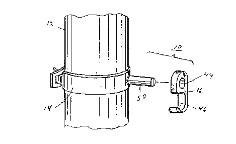
Referring to Fig. 1, there is shown a perspective view of
an electrical grounding connector 10 incorporatillg
features of the present invention attached to a pipe 12.

CA 02246177 1998-08-28
Although the present invention will be described with
reference to the embodiments shown in the drawirlgs, i t
should be urlderstood that the present inventioll could be
embodied in many different types of alternate
S embodiments. In addition, any suitable size, shaE~e or
type of elements or materials could be used.
The pipe 12 could be an electrical conduit, a water pipe,
a gas pipe or any other pipe made of electrically
conductive material and connected to ground. The
lO connector 10 is intended to be used to connect a gr-our-d
conductor 13 (see Fig. 5) to the pipe 12. The cc)nlle(- t-or
10 generall y compr:ises a band ~ 4 and a compreC~
connector 16. Referring also to Fig. 2, the band 14 is
comprised of two half band sections 18, 20. Each balld
IS section is preferably comprised of electricall y
conductive material and has a general serni-circular
shape. The first band section 18 has a first end 22 ~Ji th
a projection 24 and a seconcl end 26. The seconci end 26
has a stem section 28 which is provided as a semi-
circular projection. The second band section 20 has a
first end 30 with a mounting section 32 having a hole 34,
and a second end 36. The second end 36 has a sterm
section 38 which is provided as a semi-circular
projection. The projection 24 is sized and shaped to be
2s inserted into the hole 34 and make an interlockillg
connection of the two first ends 22, 30 to each other.
The two stem sections 28, 38 are sized arlcl shaped to mate
with each other and form a column shaped projection from
the band. When the first ends 22, 30 and second ends 26,
36 are connected to each other, the center spans 40, 92
of tile two band sections 18, 20 forrn a closed ring. rl'he
size of the inner diameter or aperture is speci f ical] y
designed to be the same or slightl y smaller than the
outer- cliameter of the pipe 12. Therefore, when the ~anc~
14 is attached around the pipe 12, it makes a tight

CA 02246177 1998-08-28
mechanical fit therewith as well as an electrical
connection. Different size bands would be used for pipes
with different outer diameters. In an alternate
embodiment, the band could be a one piece member with the
two stem sections 28, 38 on opposite ends. II1 Other
alternate embodiments, any suitable type or shape of
first end connections could be provided, any suitable
type or shape of second end stem sections could be
provided, and/or more than two band sections could be
used.
The compression connector ]6 is a one-piece metal
electrical compression connector, such as a BURNDY type
YG~-IP-C or YGHR-( connector. BURNDY is a re(~istered
trademark of ~ramatome Connectors USA Inc. However, in
alternate embodiments other suita~le types of compressioll
connectors could be used. The connector 16 has two
apertures 44, 46. In this embodiment the first aper-ture
44 is a closed sided through-hole and the second aperture
46 is an open sided through-hole. The stem halves 28, 38
2~ of the band 14, when placed against each other, are sized
and shaped to be matingly received in the first aperture
44 of the compression connector 16. The second apert~lre
46 is sized and shaped to receive an end of the conductor
13 therein.
Referring also to ~igs. 3-5, connection of the conductor
13 to the pipe 12 by the connector 10 will be described.
The two first ends 22, 30 of the band halves 18, 20 are
connected to each other to forrn a hinge. The band 14 is
then placed arourld the pipe 12. A user uses a tool, such
3() as the pliers 48 to compress the two secor-d end stem
sections 28, 38 against, or at least closely towards,
each other. The two stem sections 28, 38 thlls form a
single stem 50 OIltO which the compression connector 16 is
mounted. The stem 50 is received in the first aperture

CA 02246177 1998-08-28
44. The tool 48 can then be removed since the
compression connector 16 will retain the two stem
sections 28, 38 together. The compression connector 16
can be moved to its desired final position on the sten-l 50
and the conductor 13 is inserted in the second aperture
~6. The user then locates a compression tool 52 aroulld
the compression connector 16. The compression tool 52 is
preferably a hydraulic compression tool, suctl as the
BURNDY Y35 E-~ydraulic Crimping Tool, a battery powered
tool, such as the B~RNDY BCT500, or a power actuat~ed tool
that uses a cartridge. Iiowever, any suitable compressio
tool could be used. The user actuates the colrlpressiol-
tool 52 to compress or crimp the connector 16 onto bot}
the conductor 13 arld the sterm 50 at the same time. rlhis
forms a permanent mechanical and electrical conllec-tio
of the conductor 13 to the pipe 12. Thus, the conllectior-
is complete.
Referring now to Fig. 6, an alternate embodiment of the
first ends of the band sections is shown. In this
2() embodiment the two first ends 60, 62 have interlocking
curved clasp sections 64, 66. Referring now to Fig. 7,
another alternate embodiment of the first ends of the
band sections is shown. In this embodiment the two first
ends 70, 72 have stud sectiorls 79, -76 that are placed
against each other. A compression sleeve 78 is tllerl
placed OIl the stud sections 74, 76 and compressecl to
thereby connect the two first ends 70, 72 to each other.
Referring now to Fig. 8, an alternate embodiment of the
center spans of the band sections is ShOWIl. Irl this
3() embodiment the interior side of the center span 80 has
barbs 82. When the ban(i is attached to the pipe, tlle
barbs 82 penetrate tilrough any exterior coating on the
pipe to insure a good electrical connection between the
pipe and the band. Referring now to Fig. 9, another
alternate embodiment of the center span of one of the

CA 02246177 1998-08-28
band sections is shown. In this embodiment, the center
space 90 has threaded holes 92, 93, 94 therein at an
additional connector mounting area 96. With t~lis
embodiment, other conductors can be attached to the same
S band as the conductor 13. Referring now to Fig. 10,
another alternate embodiment of the band is shown. In
this embodiment the band 100 has a first band section 102
with a ilook 104 at its first end and a second band
section 106 with a plurality of holes 108 in its first
1() end. With this embodiment the two band sections ]Q2, 106
are adjustably connectable to each other to allow the
band 100 to be connected to different size pipes. In
alternate embodiments, other types of means to provide an
adjustable band could be provided.
lS It should be under-stooc1 that the foregoing description is
only illustrative of the invention. Various alternative
and modifications can be devices by those skilled in tile
art without departing from the invention. Accordingly, the
present invention is intended to ernbrace all such
2() alternative, modifications and variances which fall withi
the scope of the appended claims.

Representative Drawing
A single figure which represents the drawing illustrating the invention.
Administrative Status

2024-08-01:As part of the Next Generation Patents (NGP) transition, the Canadian Patents Database (CPD) now contains a more detailed Event History, which replicates the Event Log of our new back-office solution.

Please note that "Inactive:" events refers to events no longer in use in our new back-office solution.

For a clearer understanding of the status of the application/patent presented on this page, the site Disclaimer , as well as the definitions for Patent , Event History , Maintenance Fee  and Payment History  should be consulted.

Event History

Description Date
Application Not Reinstated by Deadline 2004-08-30
Time Limit for Reversal Expired 2004-08-30
Deemed Abandoned - Failure to Respond to Maintenance Fee Notice 2003-08-28
Amendment Received - Voluntary Amendment 2003-01-21
Revocation of Agent Requirements Determined Compliant 2002-12-12
Inactive: Office letter 2002-12-12
Appointment of Agent Requirements Determined Compliant 2002-12-12
Appointment of Agent Request 2002-11-27
Revocation of Agent Request 2002-11-27
Letter Sent 2002-08-06
All Requirements for Examination Determined Compliant 2002-06-12
Request for Examination Received 2002-06-12
Request for Examination Requirements Determined Compliant 2002-06-12
Application Published (Open to Public Inspection) 1999-03-09
Inactive: IPC assigned 1998-11-05
Inactive: First IPC assigned 1998-11-05
Classification Modified 1998-11-05
Inactive: Single transfer 1998-11-03
Inactive: Correspondence - Formalities 1998-11-03
Inactive: Courtesy letter - Evidence 1998-10-20
Inactive: Filing certificate - No RFE (English) 1998-10-16
Application Received - Regular National 1998-10-15

Abandonment History

Abandonment Date Reason Reinstatement Date
2003-08-28

Maintenance Fee

The last payment was received on 2002-06-12

Note : If the full payment has not been received on or before the date indicated, a further fee may be required which may be one of the following

  • the reinstatement fee;
  • the late payment fee; or
  • additional fee to reverse deemed expiry.

Patent fees are adjusted on the 1st of January every year. The amounts above are the current amounts if received by December 31 of the current year.
Please refer to the CIPO Patent Fees web page to see all current fee amounts.

Fee History

Fee Type Anniversary Year Due Date Paid Date
Application fee - standard 1998-08-28
Registration of a document 1998-11-03
MF (application, 2nd anniv.) - standard 02 2000-08-28 2000-06-19
MF (application, 3rd anniv.) - standard 03 2001-08-28 2001-07-13
Request for examination - standard 2002-06-12
MF (application, 4th anniv.) - standard 04 2002-08-28 2002-06-12
Owners on Record

Note: Records showing the ownership history in alphabetical order.

Current Owners on Record
FRAMATOME CONNECTORS INTERNATIONAL
Past Owners on Record
ANDREW T. ZWIT
Past Owners that do not appear in the "Owners on Record" listing will appear in other documentation within the application.
Documents

To view selected files, please enter reCAPTCHA code :


To view images, click a link in the Document Description column (Temporarily unavailable). To download the documents, select one or more checkboxes in the first column and then click the "Download Selected in PDF format (Zip Archive)" or the "Download Selected as Single PDF" button.

List of published and non-published patent-specific documents on the CPD .

If you have any difficulty accessing content, you can call the Client Service Centre at 1-866-997-1936 or send them an e-mail at CIPO Client Service Centre.

({010=All Documents, 020=As Filed, 030=As Open to Public Inspection, 040=At Issuance, 050=Examination, 060=Incoming Correspondence, 070=Miscellaneous, 080=Outgoing Correspondence, 090=Payment})


Document
Description 
Date
(yyyy-mm-dd) 
Number of pages   Size of Image (KB) 
Representative drawing 1999-03-18 1 7
Abstract 1998-08-27 1 14
Drawings 1998-08-27 3 69
Description 1998-08-27 7 275
Claims 1998-08-27 4 106
Filing Certificate (English) 1998-10-15 1 163
Courtesy - Certificate of registration (related document(s)) 1998-12-21 1 115
Reminder of maintenance fee due 2000-04-30 1 111
Acknowledgement of Request for Examination 2002-08-05 1 193
Courtesy - Abandonment Letter (Maintenance Fee) 2003-10-22 1 176
Correspondence 1998-10-19 1 34
Correspondence 1998-11-02 1 42
Correspondence 2002-11-24 8 210
Correspondence 2002-12-11 1 14
Correspondence 2002-12-11 1 19
Fees 2001-07-12 1 42
Fees 2002-06-11 1 51
Fees 2000-06-18 1 42