Language selection

Search

Patent 2246264 Summary

Third-party information liability

Some of the information on this Web page has been provided by external sources. The Government of Canada is not responsible for the accuracy, reliability or currency of the information supplied by external sources. Users wishing to rely upon this information should consult directly with the source of the information. Content provided by external sources is not subject to official languages, privacy and accessibility requirements.

Claims and Abstract availability

Any discrepancies in the text and image of the Claims and Abstract are due to differing posting times. Text of the Claims and Abstract are posted:

  • At the time the application is open to public inspection;
  • At the time of issue of the patent (grant).
(12) Patent Application: (11) CA 2246264
(54) English Title: A KINK INHIBITING DEVICE
(54) French Title: DISPOSITIF UTILISE POUR ELIMINER LES TORSIONS
Status: Deemed Abandoned and Beyond the Period of Reinstatement - Pending Response to Notice of Disregarded Communication
Bibliographic Data
(51) International Patent Classification (IPC):
  • F16L 3/26 (2006.01)
  • A61M 25/00 (2006.01)
  • A61M 25/02 (2006.01)
  • A61M 39/08 (2006.01)
  • F16L 3/12 (2006.01)
(72) Inventors :
  • COLLEN, JUSTIN (South Africa)
(73) Owners :
  • JUSTIN COLLEN
(71) Applicants :
  • JUSTIN COLLEN (South Africa)
(74) Agent: SMART & BIGGAR LP
(74) Associate agent:
(45) Issued:
(22) Filed Date: 1998-09-02
(41) Open to Public Inspection: 1999-03-02
Availability of licence: N/A
Dedicated to the Public: N/A
(25) Language of filing: English

Patent Cooperation Treaty (PCT): No

(30) Application Priority Data:
Application No. Country/Territory Date
97/7871 (South Africa) 1997-09-02

Abstracts

English Abstract


A kink inhibiting device is provided for inhibiting kinking in a length of
curved flexible tubing, and in particular IV or drip tubing. The device
comprises a pair of U-shaped shell halves which are joined back-to-back at
their bight portions by an integral hinge formation. The shell halves each
define channels having semi-circular cross-sectional profiles, and are formed
with connecting lands carrying studs and complemental apertures for
allowing the shell halves to mate with one another. The shell halves each
have a radius of curvature (R) which is greater than the maximum radius of
curvature at which the flexible tubing starts to kink when unsupported.


French Abstract

Dispositif utilisé pour éliminer les torsions dans une section de tube souple incurvée, en particulier un tube d'intraveineuse ou de perfusion. Le dispositif comprend une paire de demi-coquilles en U, unies dos-à-dos au niveau de leur section de boucle, au moyen d'une charnière intégrée. Les demi-coquilles sont dotées l'une et l'autre de rainures transversales semi-circulaires et comportent des surfaces d'appui munies de tiges et d'ouvertures complémentaires pour assurer leur assemblage. Les demi-coquilles ont toutes deux un rayon de courbure (K) supérieur au rayon de courbure maximal auquel un tube souple, non supporté, commence à se tordre.

Claims

Note: Claims are shown in the official language in which they were submitted.

-8-
THE EMBODIMENTS OF THE INVENTION IN WHICH AN
EXCLUSIVE PROPERTY OR PRIVILEGE IS CLAIMED ARE
DEFINED AS FOLLOWS:
1. A kink inhibiting device for inhibiting kinking in a length of curved
flexible tubing, the device comprising a conduit which is
dimensioned to accommodate the length of tubing, the conduit
including two channel-defining shell halves and connecting means for
connecting the shell halves together over the length of curved flexible
tubing, the shell halves each having a radius of curvature which is
greater than the maximum radius of curvature at which the flexible
tubing starts to kink when unsupported.
2. A kink inhibiting device according to claim 1 in which the shell
halves are substantially U-shaped in plan view.
3. A kink inhibiting device according to claim 1 in which each shell
half defines a channel which has a semi-circular cross-sectional
profile.
4. A kink inhibiting device according to claim 1 in which the shell
halves are hinged to one another.
5. A kink inhibiting device according to claim 4 in which the shell
halves are provided with an integral hinge formation, with the entire
device being unitary and being injection moulded from a plastics
material.

-9-
6. A kink inhibiting device according to claim 5 in which the shell
halves are joined back-to-back at their bight portions by the integral
hinge formation.
7. A kink inhibiting device according to claim 1 in which the shell
halves are separate from one another.
8. A kink inhibiting device according to claim 1 in which the
connection means comprise a first connecting land or flange carried
on one shell half, a second connecting land or flange carried on the
other shell half so as to provide a connecting interface, and mating
formations carried on the lands for holding the lands together in a
click or snap fit.
9. A kink inhibiting device according to claim 8 in which the mating
formations comprise studs and corresponding apertures within which
the studs are arranged to locate in a snap or friction fit.
10. A kink inhibiting device according to claim 1 in which the length of
flexible tubing is drip or IV tubing, with the device being arranged
to be fitted to that portion of the tubing proximate a spigot to which
the drip cannula or needle is connected.
11. A kink inhibiting device according to claim 1 in which the ratio of
the average radius of curvature R of central axes of the channels of
the shell halves to the inner cross sectional radius of curvature r of
the channels is greater than 3:1.

Description

Note: Descriptions are shown in the official language in which they were submitted.


- CA 02246264 1998-12-02
BACKGROUND TO THE INVENTION
THIS invention relates to a kink inhibiting device for inhibiting kinking in
a length of curved flexible tubing.
Intravenous (IV) or drip arrangements generally comprise a raised drip bag
connected by a length of IV or drip tubing to a drip cannula or needle. A
U-bend is typically formed in that portion of the tubing proximate the needle
for allowing the tubing to be fed back to the drip bag. Kinking tends to
occur in this U-bend. This causes a reduced flow of fluid into the vein
which has been targeted by the cannula. This often leads to clotting in the
vein, resulting in the painful and discomforting step of having to relocate the
cannula. In addition, once kinking has occurred, the entire drip arrangement
needs to be replaced, which is a relatively time-consuming and expensive
procedure.
It is an object of the invention to provide a device which inhibits or at least
reduces kinking in a drip or IV tube, and which can be fitted to the drip tube
when the drip is in sitll.
-

- CA 02246264 1998-12-02
,.
SUMMARY OF THE INVENTION
According to the invention there is provided a kink inhibiting device for
inhibiting kinking in a length of curved flexible tubing, the device
comprising a conduit which is dimensioned to accommodate the length of
tubing, the conduit including two channel-defining shell halves and
connecting means for connecting the shell halves together over the length of
curved flexible tubing, the shell halves each having a radius of curvature
which is greater than the maximum radius of curvature at which the flexible
tubing starts to kink when unsupported.
Preferably, the shell halves are hinged to one another, and are substantially
U-shaped in plan view, with each shell half defining a channel having a
semi-circular profile.
Conveniently, the connection means comprise a first connecting land or
flange carried on one shell half, a second connecting land or flange carried
on the other shell half so as to provide a connecting interface, and mating
formations carried on the lands for holding the lands together in a click or
snap fit.
Typically, the mating formations comprise studs and corresponding apertures
within which the studs are arranged to locate in a snap or friction fit.
Advantageously, the kink inhibiting device is unitary with an integral hinge
and is injection moulded from a hard plastics material such as polypropylene
or polyethylene.

- CA 02246264 1998-12-02
Typically, the shell halves are joined back-to-back at their bight portions.
Alternatively, the shell halves may be separate from one another.
Preferably, the ratio of the average radius of curvature R of the central axes
of the shell halves to the inner cross sectional radius of curvature r of the
channels is greater than 3:1, and is more preferably greater than 3.5:1.
BRIEF DESCRIPTION OF THE DRAWINGS
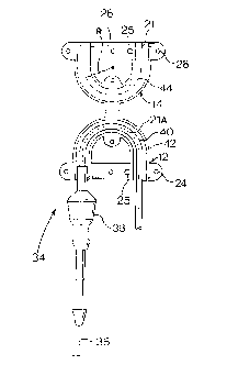
Figure 1 shows a top plan view of a kink inhibiting device of the
invention in the open position;
Figure 2 shows an underplan view of the kink inhibiting device of
Figure 1 in the open position in the process of being fitted to
a drip tube;
Figure 3 shows the kink inhibiting device of Figure 2 closed around
the drip tube;
Figure 4 shows a cross-section on the line 4-4 of Figure 3; and
Figure 5 shows a pictorial view of the kink inhibiting device of Figure
1 applied when the drip is fitted to a patient.

CA 02246264 1998-12-02
DESCRIPTION OF EMBODIMENTS
Referring first to Figure 1, a unitary kink inhibiting device 10 is injection
moulded from a relatively hard and rigid plastics material such as
polypropylene or polyethylene, and comprises first and second U-shaped
shell halves 12 and 14 which are joined back-to-back by an integral hinge
16 having a line of weakness 16A. As is clear from Figure 4, the shell
halves 12 and 14 have a semi-circular profile 18 which is dimensioned to
comfortably accommodate a drip tube 20. The shell halves 12 and 14 each
define U-shaped central axes 21 and 21A. The first shell half 12 is formed
with a first connecting land 22 extending across the opening of the U and
having three apertures 24. An additional pair of registering through-
apertures 25 are provided for allowing the device to be anchored to a patient
by being stitched to a bandage or the like. The second shell half 14 is
provided with a corresponding connecting land 26 formed with three
complemental connecting pins or studs 28 which are arranged to extend
through the corresponding apertures 24 in a snug friction or click fit when
the two shell halves are folded together into the Figure 4 position. An
additional connecting pin 28A is supported on a tag 30 which extends from
a bight of the U-shaped channel half 14, and a complemental aperture 24A
is formed in a corresponding tag 32 extending from the bight of the U-
shaped shell half 12.
In Figure 2, part of a drip arrangement or intravenous giving set 34 is shown
comprising a drip cannula or needle 36 which is fitted into a rubber
connecting spigot 38. The spigot is in turn mounted to the end of a curved
length of drip tubing 40, which leads to an elevated drip bag (not shown).
As was mentioned previously, kinking is most prone to occur in the length

- CA 02246264 1998-12-02
of curved tubing 40 proximate the spigot 38. The curved length of tubing
is consequently fitted into the first shell half 12, after which the second shell
half 14 is folded over into the Figure 3 position, with the pins 28 in the
second shell half extending through the apertures 24 in the first shell half so
as to hold the kink inhibiting device in position over the tubing.
The U-shaped shell halves typically have an inner radius of curvature of
9.5mm and an outer radius of curvature of 16.5mm, with an average radius
of curvature R at the central axes 21 and 21A of 13mm. The channels 42
and 44 typically have inner cross-sectional radii of curvature r of 3.5mm,
with the ratio of R:r being 13:3.5 or 3.7:1. This ratio is preferably above 3
in order to ensure that the drip tube 40 cannot kink when housed within the
kink inhibiting device. The outer radius of the drip tube typically ranges
from 1.5 to 1.7mm, with the result that the channels 42 and 44 provide more
than sufficient clearance to accommodate this tubing, as well as tubing
having a radius of up to 3.3mm or even 3.4mm. Naturally, the channel
dimensions as well as the radius of curvature of the shell halves may be
increased to accommodate even thicker tubing. It should be appreciated that
the propensity of the tubing to kink depends on a number of factors,
including the material from which the tubing is made, the wall thickness of
tlle tubing, and the temperature of the tubing. At room temperatures of 18~C
to 20~C, the tubing is relatively firm and kink-resistant. At higher
temperatures of 37~C or more, corresponding to the body temperature of the
patient against whom the tubing is resting, the tubing tends to soften and to
kink more easily. The kink-inhibiting device has an R:r ratio of 3 or more,
which makes allowances for such differences in temperature, material, and
wall thickness.

. CA 02246264 1998-12-02
Referring now to Figure 5, the drip arrangement or intravenous giving set
34 is shown in situ on a hand 42 of a patient, with the kink inhibiting device
10 in position. The drip cannula or needle 36 is located in a wrist vein of
the patient, and the connecting spigot 38 and drip tube 40 is anchored in
position using a length of sticking plaster 44.
A major advantage of the kink inhibiting device of the invention is that, in
contrast to kink-inhibiting sleeves and the like, it can conveniently be retro-
fitted to a drip which is already in position on a patient without the need to
remove any portion of the drip tube or to manoeuvre the drip tube
unnecessarily.
The invention is not confined to preventing or reducing kinking in a drip
tube, but may be used to prevent kinking in any flexible tube or hose which
is designed to carry a fluid and which normally undergoes bending.

Representative Drawing
A single figure which represents the drawing illustrating the invention.
Administrative Status

2024-08-01:As part of the Next Generation Patents (NGP) transition, the Canadian Patents Database (CPD) now contains a more detailed Event History, which replicates the Event Log of our new back-office solution.

Please note that "Inactive:" events refers to events no longer in use in our new back-office solution.

For a clearer understanding of the status of the application/patent presented on this page, the site Disclaimer , as well as the definitions for Patent , Event History , Maintenance Fee  and Payment History  should be consulted.

Event History

Description Date
Inactive: IPC from MCD 2006-03-12
Application Not Reinstated by Deadline 2002-09-03
Time Limit for Reversal Expired 2002-09-03
Deemed Abandoned - Failure to Respond to Maintenance Fee Notice 2001-09-04
Application Published (Open to Public Inspection) 1999-03-02
Inactive: Correspondence - Formalities 1998-12-02
Inactive: IPC assigned 1998-11-21
Inactive: First IPC assigned 1998-11-21
Classification Modified 1998-11-10
Inactive: IPC assigned 1998-11-10
Inactive: Filing certificate - No RFE (English) 1998-10-21
Filing Requirements Determined Compliant 1998-10-21
Application Received - Regular National 1998-10-16

Abandonment History

Abandonment Date Reason Reinstatement Date
2001-09-04

Maintenance Fee

The last payment was received on 2000-08-31

Note : If the full payment has not been received on or before the date indicated, a further fee may be required which may be one of the following

  • the reinstatement fee;
  • the late payment fee; or
  • additional fee to reverse deemed expiry.

Please refer to the CIPO Patent Fees web page to see all current fee amounts.

Fee History

Fee Type Anniversary Year Due Date Paid Date
Application fee - small 1998-09-02
MF (application, 2nd anniv.) - small 02 2000-09-05 2000-08-31
Owners on Record

Note: Records showing the ownership history in alphabetical order.

Current Owners on Record
JUSTIN COLLEN
Past Owners on Record
None
Past Owners that do not appear in the "Owners on Record" listing will appear in other documentation within the application.
Documents

To view selected files, please enter reCAPTCHA code :


To view images, click a link in the Document Description column. To download the documents, select one or more checkboxes in the first column and then click the "Download Selected in PDF format (Zip Archive)" or the "Download Selected as Single PDF" button.

List of published and non-published patent-specific documents on the CPD .

If you have any difficulty accessing content, you can call the Client Service Centre at 1-866-997-1936 or send them an e-mail at CIPO Client Service Centre.


Document
Description 
Date
(yyyy-mm-dd) 
Number of pages   Size of Image (KB) 
Representative drawing 1999-03-17 1 6
Abstract 1998-12-02 1 18
Abstract 1998-09-02 1 14
Description 1998-09-02 6 155
Claims 1998-09-02 2 50
Drawings 1998-09-02 2 39
Description 1998-12-02 6 194
Claims 1998-12-02 2 63
Drawings 1998-12-02 2 41
Cover Page 1999-03-17 1 42
Filing Certificate (English) 1998-10-21 1 163
Reminder of maintenance fee due 2000-05-03 1 111
Courtesy - Abandonment Letter (Maintenance Fee) 2001-10-02 1 185
Correspondence 1998-10-27 1 24
Correspondence 1998-12-02 12 350
Fees 2000-08-31 1 33