Note: Descriptions are shown in the official language in which they were submitted.
CA 02246648 1998-08-19
W O 97/306~l3 PCT/SE9,/Gn~C2
-
HARNESS
The present invention relates to a harness for hoiding and supporting at
least one pressurized gas-container. The harness includes a backplate, container-
holding means mounted on a first side of the backplate, two elongated support
means arranged on respective sides of a symmetry line that divides the backplateinto a left and a right part, wherein a first end of the carrier means is fastened to
the upper part of the backplate and the opposite, second end of said carrier
means is fastened to the lower part of the backplate, said harness further
comprising a waist belt which is fastened to the lower part of the backplate.
A carrier harness of this kind is intended particularly for firemen, although itcan also be used by underwater divers.
Harnesses of this kind will normally include a stiff or rigid backplate that is
provided on its lower end (when fitted upright on a person) with a hoider for
holding at least one gas container that contains pressurized breathing gas. The
harness will normally include a strap that functions to hold the gas container, i.e.
typically a gas bottle or gas cylinder, tightly against the backplate and that
embraces the gas container on a level with the upper part of the backplate, or
some other means that functions to hold the gas bottle against the backpiate.
Onc objcc~ of thc prc~cnt invcntion i~3 to providc ~ harnc3~ that i3 morc
f;~nd that will be felt to be more comfortable by the user than hitherto
known ha~es.
Another~of the invention is to provide a harness that will adapt to
user body movements~Q~e readily and effectively than known hamesses of this
2 5 kind.
The present invention thus~s to a harness for supporting a breathing
gas pressure-container and comprising ~ba~kplate, means provided on a first
side of the backplate for holding and supportin~ast one, although often two,
gas-filled pressure containers, two upper support stra~n the second side of the
3 o backplate, wherein first ends of said straps are fastened to~pper part of the
backplate in spaced relationship with one another, two lower sup~traps,
wherein first ends of said straps are fastened to the lower part of the bà~ate in
~p~cod rol~tionship ~r~ith onc ~nothcr, mcan~ for pair ~i3C connccting nn upp~r~
t-D S~
CA 02246648 1998-08-19
lA
A harness for retaining and/or transporting various articles is disclosed in
US patent No. 4 676 418. This harness comprises:
a framework or back plate on which a storage portion is mounted, shoulder
straps for looping around the shoulders of the wearer and connected to the
5 back plate, a waist plate mounted on the back plate for pivotal movement in a
plane generally parallel to the wearer's back so as to be pivotably laterally with
respect to the wearer, and a waist belt, secured to the waist plate, for
fastening around the waist of the wearer to hold the waist plate in position.
Further means for restricting the pivotal movement of the waist plate are
0 described.
Further, from Norwegian patent specification No. 57 445 another
harness is known. This harness comprises:
a framework or back plate on which a storage portion is mounted, a
shoulder plate mounted on the back plate for pivotal movement in a plane
generally parallel to the wearer's back so as to be pivotably laterally with
respect to the wearer, shoulder straps mounted on the ends of the shoulder platefor looping around the shoulders of the wearer and connected to the back
plate.
AA~ E~
CA 02246648 1998-08-19
W O 97/306()9 P~-T/'E9~ 2
~ IAn~
\Thc prscnt invcntion rclatc_ to .. harnc3~ for holding and supporting at
least o~ressurized gas-container. The hamess includes a backplate, container-
holding me~mounted on a first side of the backplate, two elongated support
means arranged~respective sides of a symmetry line that divides the backplate
into a left and a right~, wherein a first end of the carrier means is fastened to
the upper part of the back~e and the opposite, second end of said carrier
means is fastened to the lowe~rt of the backplate, said harness further
comprising a waist belt which is fas~d to the lower part of the backplate.
A carrier harness of this kind is in~ded particularly for firemen, although it
can also be used by underwater divers.
Harnesses of this kind will normally includ~a~tiff or rigid backplate that is
provided on its lower end (when fitted upright on a pe~with a holder for
holding at least one gas container that contains pressurize~athing gas. The
harness will normally include a strap that functions to hold the g~s~ontainer, i.e.
typically a gas bottle or gas cylinder, tightly against the backplate an~at
embraces the gas container on a level with the upper part of the backplat~
somo othor mcans that function_ to hold thc gQ~ bottlc ~y~ lc.
2 o One object of the present invention is to provide a harness that is more
flexible and that will be felt to be more comfortable by the user than hitherto
known harnesses.
Another object of the invention is to provide a harness that will adapt to
user body movements more readily and effectively than known hamesses of this
2 5 kind.
The present invention thus relates to a hamess for supporting a breathing
gas pressure-container and comprising a backplate, means provided on a first
side of the backplate for holding and supporting at least one, although often two,
gas-filled pressure containers, two upper support straps on the second side of the
3 0 backplate, wherein first ends of said straps are fastened to the upper part of the
backplate in spaced relationship with one another, two lower support straps,
wherein first ends of said straps are fastened to the lower part of the backplate in
spaced relationship with one another, means for pair-wise connecting an upper
CA 02246648 1998-08-19
WO 97/30609 PCT/SE97/00202
and a lower support strap, and a waist belt which is fastened to the iower part of
the backplate. The inventive harness is mainly characterized in that it includes on
the lower part of the second side of the backplate an at least substantially rigid
first element that extends parallel with the backplate and that is pivotally mounted
5 on the backplate at a first pivot point, wherein each of the second ends of the
elongated support means is fastened to the first element on a respective side ofsaid pivot point.
It is particularly preferred that the first pivot point lies on the symmetry line.
The first element will advantageously have the form of an elongated plate-like
0 element whose end parts can be swung about a respective pivot line
symmetrically with respect to said pivot point and parallel with and at a distance
from the symmetry line, i.e. those parts of the element that lie outside the pivot
line, i.e. at a greater distance from the symmetry line, can be pivoted forwardly of
the backplate, wherein the elongated support means are attached to said element
5 parts that can swing relative to the backplate.
According to another preferred embodiment, the waist belt is pivotally
mounted on the second side of the backplate on a second pivot point.
~ ccording to a further preferred embodiment of the invention, the waist belt
includes an at least substantially rigid second element that extends parallel to the
2 0 backplate, and two flexible strap parts whose respective ends are connected to
the second element, wherein the second element is pivotally mounted on the
backplate on the second pivot point.
According to yet another preferred embodiment, the invention relates to a
harness for carrying a pressurized breathing gas container, wherein the harness
2 5 includes a backplate, means on a first side of the backplate for holding andsupporting at least one, but often two gas-filled pressure containers, and hlvo
upper support straps on the other side of the backplate, wherein first ends of the
support straps are fastened to the upper part of the backplate in mutually spaced
relationship, two lower support straps, wherein first ends of said straps are
3 0 fastened to the lower part of the backplate in mutually spaced relationship, means
for mutually connecting an upper and a lower strap, and a waist belt that is
CA 02246648 1998-08-19
W O 97/30609 PCT/S~97/00202
fastened to the iower part of the backplate. The invention is mainly characterized
in that the harness includes on the second side of the backplate a third elementwhich is at least substantially rigid and parallel with the backplate, wherein the
third element is pivotally mounted on the backplate on a third pivot point on the
symmetry line, and wherein each of the first ends of the elongated support meansis fastened to the third element on a respective side of said pivot point.
Further embodiments of the invention will be evident from the following
detailed description of exemplifying embodiments thereof, made with reference tothe accompanying drawings, in which
Fig. 1 is a schematic front view of an earlier known harness;
I=ig. 2 is a schematic front view of a preferred embodiment of an inventive
hamess;
Fig. 3 is a schematic front view of another preferred embodiment of an
inventive hamess; and
Fig. 4 is a schematic sectional view of part of the harness shown in Fig. 2,
taken through the symmetry line.
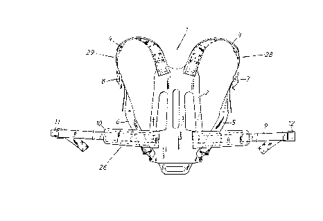
Fig. 1 is a front view of a typical harness 1, comprising a rigid backplate 2.
When the harness 1 is in use, i.e. worn by a person who stands upright, the
illustrated side of the backplate 2 will be in contact with the wearer's back.
2 o Provided on the opposite side of the backplate 2, in the lower part thereof, is a
device (not shown) that functions to support one or two breathing-gas pressure
containers. Although not shown, the upper half of the backplate 2 will have
connected thereto a strap that embraces the container, i.e. the gas cylinder, and
holds the container fixed against the backplate 2.
2 5 Two upper support straps 3, 4 are fastened to the upper part of the
backplate 2 in mutual spaced relationship. Two lower support straps 5, 6 are
fastened to the lower part of the backplate 2 in mutually spaced relationship.
Those ends of the straps 3-6 that are not secured to the backplate Z are joined in
pairs by a respective buckle means 7, 8 that mutually connects respective straps3 o 3, 5 and 4, 6. The straps 3, 5 and 4, 6 form respective support devices 28 and 29.
The support devices 28 and 29 form together with the backplate 2 closed loops
CA 02246648 l998-08-l9
W 097/30609 PCT/SE97/00202
whose size can be adjusted with the aid of the buckles 7, 8.
A waist belt 26 includes two belt sections 9, 10 and the ends of the belt are
fastened to the lower part of the backplate 2 in mutual spaced relationship. Theends of the two waist-belt sections 9, 10 that lie distal from the backplate 2 can be
joined together by means of a respective buckle part 1 1, 12, which enables the
length of belt to be adjusted. The size of the loop formed by the waist-belt
sections 9, 10 and the backplate 2 can be adjusted by means of the buckle 11,
12. The buckle 1 1, 12is a part of the waist belt 26.
Those parts of an inventive harness 1 of a first embodiment of the
0 invention that find correspondence in the aforedescribed known harness havebeen identified by the same references as those used above. In the Fig. 2
illustration, the two lower support straps 5, ~ are attached to a first plate-like
element 24 which is pivotally mounted on the backplate 2 for pivotal movement
about a first pivot point 25. Although the pivot point 25 will preferably lie in the
lower part of the symmetry line 27 of the backplate 2, it may conceivably lie in the
immediate vicinity of said symmetry line. The planar element 24iS pivotally
mounted on the backplate 2 on the pivot point 25 by means, e.g., of a pivot shaft
or pin that holds the element 24 against the backplate 2. This pivot shaft 25
extends perpendicular to the plane of the element 24 and the backplate 2.
2 0 As illustrated in Fig. 3, the first element 24iS preferably an elongated
plate-like element whose outer parts can pivot or swing parallel to the symmetryline 27, symmetrically in spaced relationship with the pivot point 25. This is
achieved by means of hinge lines 33 that extend transversely to the long axis ofthe element 24, such as to enable said outer ends of said element to fold
2 5 forwards away from the backplate 2. The support devices 28,29 are attached to
these pivotal par~s of the backplate 2.
As evident from Fig. 2, the waist-belt sections 9, 10 are attached to the
outer ends of a plate-like second element 13 attached to the other side of the
backplate 2. Similar to the planar first element 24, the planar second element 13
3 0 is pivotally mounted to the backplate 2 on a pivot point 14 that also functions to
hold the element against the backplate 2, said pivot point having the form of a
CA 02246648 1998-08-19
W O 97/30609 PCT/SE97/00202
pivot shaft, for instance. The pivot shaft or pivot point 14 is disposed
perpendicularly to the plane of the element 13 and the backplate 2. The waist belt
26 may alternatively be a one-piece structure that is pivotally connected to thebackplate 2. The waist belt 26 may also be constructed in the manner shown in
Fig. 1, i.e. attached to the backplate 2.
Fig. 3 illustrates a preferred embodiment in which the second element 13
includes two slots 16 that are spaced equidistantly from the pivot point 14, said
slots coacting with respective pins 15 on the backplate 2. These slots 16 limit the
extent to which the waist belt 26 can be swung around the pivot point 14. The pins
15 are preferably headed pins so as to hold the second element 13 more
effectively against the backplate 2 and so as to obtain a more stable harness 1.Naturally, the slots 16 may be provided in the backplate 2 and the pins in the
element 3.
The planar first element 24 may also conveniently be provided with
movement-limiting devices corresponding to those that delimit movement of the
second element 13. It is beneficial to enhance abutment of the element 24 with
the backplate 2, therewith providing a more stable harness.
In the case of the Fig. 3 embodiment, the upper support straps 3, 4 are
also attached to a third plate-like element 17. This third element may be rigidly
2 o disposed in the upper part of the backplate 2, or, as preferred, pivotally attached
to the upper part of said plate 2 with the pivot point 18 on the symmetry line in the
upper part of the backplate 2. It is also beneficial in this case to enhance
abutment of the third element 17 with the backplate 2, with the aid of mutually
coacting slots and pins, therewith improving stability of the harness.
2 5 The pivot shaft 18 on which the third element 17 pivots may alternatively
be mounted in a gap 30 that extends along the symmetry line 27. The gap 30 is
provided in the backplate 2. The third pivot point, the pivot shaft 18, is ioined to
the second pivot point 14 or to the lower part of the backplate 2 by means of anelastic or resilient device 19. This device functions to draw the third pivot point 18
3 o towards the lower position of the gap. Alternatively, a gap 30' may be provided in
the third element 17, wherein the elastic or resilient device 19 connects the third
CA 02246648 l998-08-l9
W097J30609 PCT/SE97/00202
element 17 to the second pivot point 14 or to the lower part of the backplate 2.Whichever alternative is used, it is essential that the element 17 is movable inrelation to the second pivot point 14 or the lower part of the backplate 2.
Thus, the third element 17 of the inventive hamess may either be rigidly
connected to the backplate 2 or pivotally connected thereto, said upper support
straps 3, 4 being connected to said third element. The pivotal arrangement may
be such as to enable the third eiement to move in relation to respective first and
second elements 24 and 13. The second element 13, which is a part of the waist-
belt arrangement 9, 10, may be rigidly or pivotally mounted to the backplate 2.
0 According to one preferred embodiment (see Fig. 4), the second element13 is comprised of two mutually parallel, flat plates 21 and 22 that iie one on top
of the other. The first plate 21 may be fixed to the backplate 2 in the same way as
the first element 24. The first plate 21 lies between the backplate 2 and the
second plate 22. The two plates 21,22 are mutually hinged at their upper ends,
for instance by hinge means 23. The flexible parts of the waist-belt are connected
to the second plate 22, in a manner similar to that of the first element 13
according to the previous embodiment.
As described with reference to element 13 of a previous embodiment, slots
and pins may be provided in/on the first plate 21 outside the pivot point 14.
2 o Corresponding co-acting means may also be provided on the third element 17 and on the ~ackplate 2.
In the case of a further embodiment, the pivot point 25 of the first element
24 lies beneath the pivot point 14 of the second element 13. The distance
between the elements 24 and 13is such as to enable said elements to be rotated
2 5 freely without coming into contact with each other, even when the elements 24
and 13 move towards each other on one side of the symmetry line 27.
In the case of yet another embodiment, the pivot point 25 of the first
element 24 lies above the pivot point 14 of the second element 13. The distance
between the elements 24 and 13 is such as to enable said elements to be rotated
3 o without coming into contact with each other even when said elements move
towards each other on one side of the symmetry line 27.
CA 02246648 1998-08-19
W O 97/30609 PCT/SE97/00202
In one particularly preferred embodiment, the first and the second pivot
points 25, 14 are mutually coincidental and thus seated on a common pivot shaft.In this case, it is preferred that the first element 24 is located between the
backplate 2 and the second element 13. The common pivot shaft 25, 14 may also
5 be mounted in a gap in the backplate 2 and connected to one end of an elastic or
resilient element 19 whose other end is attached to the upper part of the
backplate 2 or to the pivot shaft 18. The gaps may, of course, alternatively be
provided in the elements 13 and 14 instead of the backplate 2, the main thing
being that said relative movement can be achieved.