Language selection

Search

Patent 2246810 Summary

Third-party information liability

Some of the information on this Web page has been provided by external sources. The Government of Canada is not responsible for the accuracy, reliability or currency of the information supplied by external sources. Users wishing to rely upon this information should consult directly with the source of the information. Content provided by external sources is not subject to official languages, privacy and accessibility requirements.

Claims and Abstract availability

Any discrepancies in the text and image of the Claims and Abstract are due to differing posting times. Text of the Claims and Abstract are posted:

  • At the time the application is open to public inspection;
  • At the time of issue of the patent (grant).
(12) Patent: (11) CA 2246810
(54) English Title: EASY INSERT TUBE CLEANER
(54) French Title: NETTOIE-TUBE FACILE A INSERER
Status: Term Expired - Post Grant Beyond Limit
Bibliographic Data
(51) International Patent Classification (IPC):
  • B08B 9/02 (2006.01)
  • B08B 9/04 (2006.01)
  • F28G 1/12 (2006.01)
(72) Inventors :
  • SAXON, GREGORY J. (United States of America)
  • KRYSICKI, JERZY (United States of America)
(73) Owners :
  • CONCO SYSTEMS, INC.
(71) Applicants :
  • CONCO SYSTEMS, INC. (United States of America)
(74) Agent: SMART & BIGGAR LP
(74) Associate agent:
(45) Issued: 2003-03-25
(22) Filed Date: 1998-09-08
(41) Open to Public Inspection: 1999-03-12
Examination requested: 1998-09-08
Availability of licence: N/A
Dedicated to the Public: N/A
(25) Language of filing: English

Patent Cooperation Treaty (PCT): No

(30) Application Priority Data:
Application No. Country/Territory Date
08/928,847 (United States of America) 1997-09-12

Abstracts

English Abstract


A tube cleaner that provides for easy insertion into an
open end of a tube has a shaft, a nose portion and tail portion,
and a plurality of scraper devices secured to the shaft. The
scraper devices are U-shaped and have a base and at least two leg
portions which have terminal scraping sections. A tongue is
provided on the leg portion which extends from the leg portion
rearwardly and outwardly to a position adjacent the scraping
section of the scraper device.


French Abstract

Nettoie-tube pouvant être inséré facilement par l'extrémité ouverte d'un tube. Il comporte une tige, une partie avant et une partie arrière, et plusieurs dispositifs de raclage fixés à sa tige. Les dispositifs de raclage sont en forme de U et possèdent une base et au moins deux éléments verticaux qui portent des sections de raclage à leur extrémité. Une languette se trouve sur l'élément vertical et va de l'élément vertical vers l'arrière et vers l'extérieur jusqu'à un emplacement tout près de la section de raclage du dispositif.

Claims

Note: Claims are shown in the official language in which they were submitted.

CLAIMS:
1. A tube cleaner comprising a shaft having a nose
portion at a front end and tail portion at a rear end
thereof; and a plurality of spaced scraper devices secured
to the shaft intermediate the nose portion and tail portion,
each said scraper device comprising a U-shaped scraper
having a base and at least two leg portions, said leg
portions extending in the direction of said tail portion and
having scraping sections extending outwardly from a terminal
end thereof; and a tongue an each said leg portion extending
therefrom rearwardly and outwardly to a position adjacent
said scraping section of the respective leg portion.
2. The tube cleaner as defined in Claim 1 wherein
each scraping section has a scraping edge and each tongue
has an outer edge, with said outer edge of each tongue
spaced a distance from said shaft which is slightly less
than the distance of the respective scraping edge from said
shaft.
3. The tube cleaner as defined in Claim 1 wherein
each scraper device is formed from steel and said tongue is
punched out of the respective leg portion.
4. The tube cleaner as defined in Claim 1 wherein
each scraper device is formed of carbon steel.
5. The tube cleaner as defined in Claim 1 wherein
each scraper device is formed of stainless steel.
6. The tube cleaner as defined in Claim 4 wherein
each tongue has an outer edge which is spaced a distance
from said shaft which is slightly less than a distance of a
scraping edge of the respective scraping section from said
shaft.
5

7. The tube cleaner as defined in Claim 6 wherein the
distance from the outer edge of each tongue to said shaft
and the distance from the scraping edge of the respective
scraping section to said shaft differ by about 0.010 inch.
8. The tube cleaner as defined in Claim 1 wherein
each tongue is formed by punching the same from the
respective leg portion.
9. A tube cleaner comprising a shaft having a nose
portion at a front end and tail portion at a rear end
thereof; and a plurality of spaced scraper devices secured
to the shaft intermediate the nose portion and tail portion,
each said scraper device comprising a U-shaped scraper
having a base and at least two leg portions, said leg
portions extending in the direction of said tail portion and
having scraping section extending outwardly from a terminal
end thereof and each scraping section having a scraping
edge; and a tongue on etch said leg portion extending
therefrom rearwardly and outwardly to a position adjacent
said scraping section of the respective leg portion, each
tongue having an outer edge which is spaced a distance from
said shaft which is slightly less than the distance of the
respective scraping edge from said shaft.
6

Description

Note: Descriptions are shown in the official language in which they were submitted.


CA 02246810 1998-09-08
EASY INSERT TUBE CLEANER
Field of the Invention
The present invention is to a tube cleaning device for
use in cleaning the inner wall of a tube or conduit, and more
specifically to a tube cleaner that is insertable into an open end
of a tube, such as a condenser tube, and forced through the tube by
a fluid, such as water, discharged from pressurized fluid gun to
remove deposits on the inner wall surface of the tube.
Background of the Invention
In the cleaning of the inner wall of tube, such as
condenser tubes, in power plants, to improve the efficiency of heat
transfer therethrough, a resilient scraping tool is inserted into
an open end of the tube and a pressurized fluid is charged to the
open end of the tube to propel the scraping tool through the tube.
During passage through the tube, the scraping tool scrapes deposits
from the inner wall of the tube and discharges the deposits from
the other end of the tube. Such tube cleaners have been used
extensively and examples of typical such tube cleaners are shown,
for example, in U.S. 2,170,997; U.S. 2,418,509; U.S. 2,734,208, and
U. S. 4, 281, 432 . These tube cleaners use scraping elements that are
spaced along a shaft, with scraping blades of adjacent scraping
elements offset from each other so that the deposits on the inner
tube wall are scraped away along the entire 360° inner
circumference thereof. The scraper elements, with the scraper
blades, are usually formed from steel and are flexible enough to be
inserted into the open end of a tube while making contact with and
removing deposits from the tube wall upon passage through the tube.
1

CA 02246810 2002-06-25
?44Q5-46
It is an object of the rresent invention to
provide a tube cleaner whlcr- is m«E> ~.as. 1y inserted into an
open end of a tube to be ::leaned.
Summary of the Invention
The easy insert vLCbe cleaner ot_ the preserut
invention has a snaat wit=ty a nose portion at the front end,
a tail portion at the rear end, and ., pl!~rality of spaced
scraper devices between tie nose portion and tail portion.
The sc:rapez device is <i !)-sr~aped scrappier having a base and
:~0 a-~ least two leg porti~lns; ~Jitrs each 1_~~g port:ion. extending
ir: the direction of the t«W rcvrtion of -rhe tube cleaner.
Scraping secti~:>ns are provided or:. +~hE~, terrnina~_ ends of th,~~
leg portions of the scraper device wr::i_ch extend radially
outwardly from the shaat ~f: t:he tube _,l.e<~ner. A tongue is
I5 provided on each leg porti.or. of: the ,_~;:l:aper device which
extends therefrom rearwaral_y and outward l y to a position
adjacent the scraping sec:. t: ion o.f the :respective l.eg port ion.
The tongue i.-; preferably ,~ sect:ion pathetically cut from the
leg portion of the scraper devTi.ce anci pert outwardly so as
2O? to be outwardl.~.,~ and re:~rw,zz:dly exzem:::~ng.
According to an~~ther aspecT of the ir:vention,
there i.s provided a tube ~~leaner comp~_is.i.ng a shaft having a
nose portion at a front c;:;d and tail por_t:i.on at a rear er~d
thereof; and a plurality of spaced scr_.aper de~jices secured
25 to the shaft intermediate the no~~e por~v~~n anc' tail portion,
each said scraper devic.-e ~.~ompri.sing a J-~hapE:d scraper
having a base and at least. two leg portions, said leg
portions extending in the direct Lon c~~.v :».id t:ail portion and
having scrapincsections ~.~xtending oa:t~wardly frerr, a terminal
30 end thereof and each sr_rapi.ng ~;ecti~m :~u_,.~ing a scraping
edge; and a Tongue on eacrl said leg portion extending

CA 02246810 2002-06-25
74445-46
therefrom rearwardly and outwardly to a position adjacent
said scraping section of tie respective leg portion, each
tongue having an outer edge which is spaced a distance from
said shaft which is slightly less than the distance of the
respective scraping edge from said shaft.
Brief Description of the Drawings
The easy insert tube cleaner of the present
invention will be more read ily under:~tcod by reference to
the following descriptic>n and the accompanying drawings,
wherein:
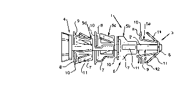
Figure 1 is a side elevational view of an
embodiment of an easy insert tube cleaner of the present
invention;
Figure 2 is a front view of the easy insert tube
cleaner of Figure l;
2a

CA 02246810 1998-09-08
Figure 3 is a cross-sectional view through one of the
scraper devices used on the easy insert tube cleaner shown in
Figure 1; and
Figure 4 is a view showing insertion of the easy insert
tube cleaner of the present invention into the open end of a tube
to be cleaned.
Detailed Description
The tube cleaner of the present invention is constructed
so as to enable easy insertion into an open end of a tube, such as
a condenser tube, that is to be cleaned. The tube cleaner is made
of a metal such as carbon steel or stainless steel which provides
sufficient strength and resiliency to scrape deposits from the
inner wall of a tube through which the tube cleaner is passed.
Referring now to the drawings, an easy insert tube
cleaner 1 is shown that has shaft 2 with a nose portion 3 at the
front end and a tail portion 4 at the rear end thereof. The nose
portion 3 may have a rivet head which secures scraper devices on
the shaft 2, while the tail portion 4 is adapted to provide a
surface for impingement of pressurized fluid thereon to drive the
tube cleaner through a tube, as known in the art. A plurality of
scraper devices 5, shown as four scraper devices, 5a, 5b, 5c and 5d
in Figure 1, are spaced along the shaft 2 between the nose portion
3 and tail portion 4. The scraper devices 5 are U-shaped and have
a base 6 and at least two leg portions 7 which extend in the
direction of the tail portion 4 of the easy insert tube cleaner 1
and have a scraping section 8 at the terminal end 9 of the leg
portion 7 which scraping section 8 has a scraping edge 10. The
scraper devices 5 are positioned along the shaft of the easy insert
tube cleaner 1 in a manner such that the leg portions 7 and
3

CA 02246810 1998-09-08
scraping edges 10 of adjacent scraper devices 5 are offset from
each other. Such positioning is known in the art so as to provide
scraping completely around the circumference of a pipe internal
surface.
In the present easy insert tube cleaner 1, a tongue 11 is
provided on the leg portion 7 of the scraper device 5, which tongue
extends from the leg portion rearwardly and outwardly to a position
adjacent the scraping edge 10 of the scraping section 8 of the
scraper device 5. As shown in the drawings, the tongue 11 extends
outwardly~from the leg portion 7 and has an outer edge 12, which is
spaced a distance d from the shaft 2 which is substantially equal
to, but less than the distance dl which is the distance of the
scraping edge 10 or the scraping section 8 from the shaft 2 of the
easy insert tube cleaner 1. Preferably, the outer edge of the
tongue 11 is a distance d which is about 0.010 inch less than the
distance dl'
The tongue 11 is readily formed by stamping the same out
of the metal substrate that forms the leg portion 7 of the scraper
device 5.
The provision of the tongue 11 on the leg portion 7 of
the scraper device 5, causes the leg portions 7 to bend inwardly
upon insertion into a tube 12, as indicated by the arrows in Figure
4, and thus forces the leg portions 7 to move together and provides
for a less severe contact with the scraping section 8 of the tube
cleaner 1 with the end wall of the tube. By thus moving the leg
portions 7 together, easier insertion of the tube cleaner 1 into an
open end of a tube is effected.
4

Representative Drawing
A single figure which represents the drawing illustrating the invention.
Administrative Status

2024-08-01:As part of the Next Generation Patents (NGP) transition, the Canadian Patents Database (CPD) now contains a more detailed Event History, which replicates the Event Log of our new back-office solution.

Please note that "Inactive:" events refers to events no longer in use in our new back-office solution.

For a clearer understanding of the status of the application/patent presented on this page, the site Disclaimer , as well as the definitions for Patent , Event History , Maintenance Fee  and Payment History  should be consulted.

Event History

Description Date
Inactive: Expired (new Act pat) 2018-09-08
Change of Address or Method of Correspondence Request Received 2018-03-28
Inactive: Late MF processed 2010-11-02
Letter Sent 2010-09-08
Inactive: IPC from MCD 2006-03-12
Grant by Issuance 2003-03-25
Inactive: Cover page published 2003-03-24
Pre-grant 2003-01-09
Inactive: Final fee received 2003-01-09
Notice of Allowance is Issued 2002-10-16
Letter Sent 2002-10-16
Inactive: Approved for allowance (AFA) 2002-09-26
Inactive: Entity size changed 2002-09-03
Amendment Received - Voluntary Amendment 2002-06-25
Inactive: S.30(2) Rules - Examiner requisition 2002-03-14
Application Published (Open to Public Inspection) 1999-03-12
Classification Modified 1998-12-03
Inactive: First IPC assigned 1998-12-03
Inactive: IPC assigned 1998-12-03
Application Received - Regular National 1998-10-21
Filing Requirements Determined Compliant 1998-10-21
Inactive: Filing certificate - RFE (English) 1998-10-21
All Requirements for Examination Determined Compliant 1998-09-08
Request for Examination Requirements Determined Compliant 1998-09-08

Abandonment History

There is no abandonment history.

Maintenance Fee

The last payment was received on 2002-08-06

Note : If the full payment has not been received on or before the date indicated, a further fee may be required which may be one of the following

  • the reinstatement fee;
  • the late payment fee; or
  • additional fee to reverse deemed expiry.

Please refer to the CIPO Patent Fees web page to see all current fee amounts.

Owners on Record

Note: Records showing the ownership history in alphabetical order.

Current Owners on Record
CONCO SYSTEMS, INC.
Past Owners on Record
GREGORY J. SAXON
JERZY KRYSICKI
Past Owners that do not appear in the "Owners on Record" listing will appear in other documentation within the application.
Documents

To view selected files, please enter reCAPTCHA code :


To view images, click a link in the Document Description column. To download the documents, select one or more checkboxes in the first column and then click the "Download Selected in PDF format (Zip Archive)" or the "Download Selected as Single PDF" button.

List of published and non-published patent-specific documents on the CPD .

If you have any difficulty accessing content, you can call the Client Service Centre at 1-866-997-1936 or send them an e-mail at CIPO Client Service Centre.


Document
Description 
Date
(yyyy-mm-dd) 
Number of pages   Size of Image (KB) 
Cover Page 2003-02-18 1 31
Description 1998-09-08 4 169
Abstract 1998-09-08 1 14
Drawings 1998-09-08 2 31
Claims 1998-09-08 2 72
Cover Page 1999-03-31 1 37
Representative drawing 1999-03-31 1 7
Claims 2002-06-25 2 87
Description 2002-06-25 5 205
Courtesy - Certificate of registration (related document(s)) 1998-10-21 1 114
Filing Certificate (English) 1998-10-21 1 163
Reminder of maintenance fee due 2000-05-09 1 111
Commissioner's Notice - Application Found Allowable 2002-10-16 1 163
Maintenance Fee Notice 2010-10-20 1 171
Late Payment Acknowledgement 2010-11-15 1 164
Correspondence 2003-01-09 1 35
Correspondence 2001-08-02 1 30
Correspondence 2000-08-17 1 25
Fees 2010-11-02 2 61