Note: Descriptions are shown in the official language in which they were submitted.
CA 02246934 1998-09-11
.
- TITLE
DRIVESHAFT ASSEMBLY WITH
VENTED NOISE REDUCTION STRUCTURE
BACKGROUND OF THE INVENTION
This invention relates in general to noise reduction structures for use in vehicle
dliveshaft assemblies. In particular, this invention relates an improved noise reduction
structure that has a passage-vay or other opening formed therethrough for providing a
o vent between a vent opening folmed in an end fitting secured to one end of a
dliveshaft tube and intelior chambers defined within the dliveshaft tube when the
noise reduction structure is disposed therein.
Torque tr~lncmitting shafts are widely used for tTansferTing rotational power
between a source of rotational power and a rotatably driven mt~-~h~lnicm An example
of a torque tTancmitting shaft is a driveshaft tube used in a vehicle dliveshaftassembly. The driveshaft assembly tTansmits rotational power from a source, such as
an engine, to a driven component, such as a pair of wheels. A typical vehicle
dliveshaft assembly includes a hollow cylindrical driveshaft tube having an end fitting
secured to each end thereof. Usually, the end fittings are embodied as end yokeswhich are adapted to cooperate with respective universal joints. For example, a
driveshaft assembly of this general type is often used to provide a rotatable dliving
connection between the output shaft of a vehicle transmission and an input shaft of an
axle assembly for rotatably driving the vehicle wheels. Traditionally, driveshaft tubes
were made from steel. More recently, aluminum driveshafts have been developed
because of their lighter weight.
One problem encountered by all types of driveshaft assemblies is their
tendency to produce and tTansmit sound while tTansfelTing the power of the engine to
the axle assembly. It is known that any mechanical body has a natural resonant
frequency. This natural resonant fiequency is an inherent chalactelistic of the
30 mechanical body and is based upon many factors, including its composition, size and
CA 02246934 1998-09-ll
shape. The natural resonant frequency is made up of many sub-frequencies, often
referred to as haumonics. As the vehicle is operated through its normal speed range
(i.e. from 0 mph to about 80 mph), the rotational velocity of the dliveshaft assembly
changes (i.e. from 0 rpm to about 5000 rpm). As the rotational velocity of the
dliveshaft changes, it passes through the harmonic frequencies of the body's resonant
frequency. When the rotational velocity of the dliveshaft passes through these
harmonic frequencies, vibration and noise may be amplified since the two frequencies
are ~yll~,LI~ d and the rotational energy of the driveshaft is convelted into vibration
and noise. This noise can be undesirable to passengers liding in the vehicle. Thus, it
o would be advantageous to deaden or reduce the sound produced by a vehicle
dliveshaft assembly in order to provide the p~ ngf rs with a more quiet and
comfortable ride.
Various attempts have been made to deaden the sound produced by vehicle
driveshaft tubes. One general direction that many of these attempts have followed is
to place a noise absorbing/deadening stmctule within the driveshaft. For example, one
attempt involves disposing a hollow cylindrical cardboard inselt inside an aluminum
driveshaft tube to deaden the sound. However, the cardboard insert required external
rubber ribs to prevent it fi-om sliding inside the aluminum dliveshaft tube. As a result,
the cardboard insert is relatively complicated and expensive to employ. It is also
known to place a solid noise reduction stlucture within the driveshaft tube to absorb
noise and vibration. A typical noise reduction structure is a generally cylindrical
member having a predet~rmined length which is disposed within a driveshaft tube in a
press fit relationship with the inner sulface of the driveshaft tube. Typically, the noise
reduction structure is positioned within the driveshaft tube at a location where the
amplitude of a standing wave caused by the reflection of the sound waves back and
forth along the driveshaft tube is at its maximum value. If more than one noise
reduction structure is disposed therein, the first noise reduction sùucture is located a
certain distance inward fi om one of the ends of the driveshaft tube and the remaining
noise reduction structures are then spaced apart, typically at equal intervals. As noted
CA 02246934 1998-09-11
previously, the typical driveshaft assembly fulther includes an end fitting secured to
each end of the dliveshaft tube.
In any hollow dliveshaft assembly, air can become trapped within its intemal
space when the two end fittings are secured to the hollow driveshaft tube. In the past,
this space was vented by forming a vent opening in one of the two end fittings secured
to the opposite ends of the dliveshaft tube. The vent opening prevents an undesirable
vacuum or pressure from occuuring within the dliveshaft tube. However, the use of
one or more solid noise reduction shuctures within the dliveshaft tube prevents some
of the intemal spaces from being vented through the vent opening. If a noise
reduction structure is disposed within the dliveshaft tube, the interior of the dliveshaft
tube is divided into two chambers, one of which is vented and one of which is not.
Similarly, if multiple noise reduction shuctures au-e disposed therein, the interior of the
dliveshaft tube is divided into several chambers, with only one of these chambers
being vented. While a vent opening could be fommed thuough each of the end fittings,
it is preferable to avoid the time and expense involved with such an additional
m~nnf~tllring step. In addition, this step would not fully vent the interior of the
driveshaft tube if two or more noise reductioll sbuctures are disposed therein. Thus, it
would be desirable to provide an improved noise reduction shucture that insures that
each of the interior chambers of the driveshaft tube is properly vented duling use.
SUMMARY OF THE INVENTION
The invention relates to a noise reduction shuct ue for use in a vehicle
driveshaft assembly that insures that each of the interior chambers of the driveshaft
tube is properly vented duling use. The noise reduction shucture is a solid member
having a pre-lrt~lmin~d length and a cross sectional shape which collesponds
generally to the cross sectional shape of the driveshaft tube. Preferably, the noise
reduchion shucture has an outer diameter which is approximately equal to, or slightly
larger than, the inner diameter of the driveshaft tube. As such, the noise reduction
shucture engages the inner surface of the dliveshaft tube in a light press fit
3u relationship. Each noise reduction shucture has a passageway, groove, or other
CA 02246934 1998-09-ll
opening formed therein which extends axially throughout its length. In a preferred
embodiment, an axially-extending groove is formed on the outer c;~ r~l~.ltial
surface of the noise reduction structure. The groove provides for free air flow from
one end of the noise reduction structure to the other, thereby insuring that each of the
interior chambers of the driveshaft tube is properly vented during use.
Various objects and advantages of this invention will become apparent to those
skilled in the alt fi-om the following detailed description of the preferred embodiment,
when read in light of the accompanying drawings.
o BRIEF DESCRIPTION OF THE DRAWINGS
Fig. 1 is a schematic view in elevation of a prior alt vehicle drive train
including a dlive line assembly.
Fig. 2 is a side view, paltially in cross section and paltially in schematic views,
of the prior alt drive line assembly illustrated in Fig. 1.
Fig. 3 is a side view, paltially in cross section and paltially in schematic views,
of a dlive line assembly having a noise reduction structure disposed within the
driveshaft tube in accordance with this invention.
Fig. 4 is a schematic view in perspective of one of the noise reduction
structures illustrated in Fig. 3.
DETAILED DESCRIPTION OF THE PREFERRED EMBODIMENT
Referring now to the drawings, thele is illustrated in Fig. I a vehicle drive train,
indicated generally at 10, in accordance with this invention. The illustrated vehicle
drive train system 10 includes a clutch/transmission assembly 12 that is connected to
an axle assembly 14 through a drive line assembly 15. The drive line assembly 15includes a hollow cylindlical driveshaft tube 16 that is connected between an output
shaft (not shown) of the clutch/~ ion assembly 12 and an input shaft (not
shown) of the axle assembly 14 by a pair of universal joints 18. As is typical in
vehicle drive train systems of this type, the output shaft of the clutch/ù ansmission
assembly 12 and the input shaft of the axle assembly 14 aue not co-axially aligned.
CA 02246934 1998-09-11
The universal joints 18 are provided at each end 20 of the driveshaft tube 16 torotatably connect the dliveshaft tube 16 to the ouhput shaft of the clutch/llA.~ cion
assembly 12 and the input shaft of the axle assembly 14, while allowing a limited
amount of mic~lignm~ nt of the rotational axes thereof. The connection between the
5 ends 20 of the driveshaft tube 16 and the universal joints 22 is usually accomplished
by tube yokes 22.
Fig. 2 illushrates the sh-ucture of the drive line assembly 15 in detail. As shown
therein, the dliveshaft tube 16 is an elongated, hollow cylindrical tube having an axial
length L defined by the distance between the two ends 20 thereof. The driveshaft tube
o 16 includes an inner cylindrical surface 24 that extends the length thereof and defines
an internal diameter D. The driveshaft tube 16 can be formed from a single piece of
metal. Alternatively, multiple piece driveshaft tubes can be used. In addition, the
driveshaft 16 can be folmed having a larger diameter center portion, an end portion
having a reduced diameter, and a diameter reducing poltion positioned between the
center and end portions. This type of driveshaft tube is more fully described inassignee's commonly owned U.S. Patent No. 5,643,093, issued July 1, 1997, the
disclosuue of which is incorporated herein by reference. The driveshaft tube 16 can be
formed from any suitable material. Typically, the driveshaft tube 16 is folmed from
steel or an aluminum alloy. Prefelably, the driveshaft tube 16 is folmed from an20 aluminum alloy. Suitable methods for folming the driveshaft tube 16 are well known
to persons skilled in the alt.
The ends 20 of the driveshaft tube 16 are open and are adapted for receiving an
end fitting 22. In the illushrated embodiment, a tube yoke 22 is disposed within each
end 20. In general, each tube yoke 22 typically includes a tube seat 26 at one end and
25 a lug sh-ucture 28 at the other end. The tube seat 26 is a generally cylindrical-shaped
member which is adapted to be inselted into an open end of the driveshaft tube 16.
Accordingly, the tube seat 26 enables torque to be hansmitted between the driveshaft
tube 16 and the tube yoke 22. Typically, the tube yoke 22 is secured to the driveshaft
tube 16 by a weld. In the illushrated embodiment, a circle weld 30 is made around the
30 ci--,.u~ ce of the intelface between the driveshaft tube 16 and the tube yoke 22.
CA 02246934 1998-09-11
Once assembled, the tube yokes 22 and the inner surface 24 of the dliveshaft tube 16
define a closed interior chamber 27. In order to prevent the air hrapped within the
interior chamber 27 from creating an undesirable vacuum or pressurized conditionwithin the dliveshaft tube 16, a vent opening 22a is formed in at least one of the tube
yokes 22. The vent opening 22a provides fluid communication between the interiorchamber 27 and the ahmosphere~ thereby preventing a vacuum or ~ uli~d condition
from occurring within the dliveshaft tube 16.
The lug sh-ucture 28 of each tube yoke 22 is operatively connected to a cross 31used in each universal joint 18. Each universal joint 18 also includes a second yoke
o 32 or 34 as shown in Fig. 2. Each yoke 32 and 34 is operatively connected to a
connecting shaft 36 and 37, respectively. One of these connecting shafts 36 may
connected to tr~ncmiccion 12, while the other cwulc~ lg shaft 37 may be connected to
the axle assembly 14. In the illushrated embodiment, yoke 32 is a slip yoke having
internal splines 38 which cooperate with extemal splines 40 on the connecting shaft
36 to allow the yoke 32 and the connecting shaft 36 to be axially movable with respect
to one another.
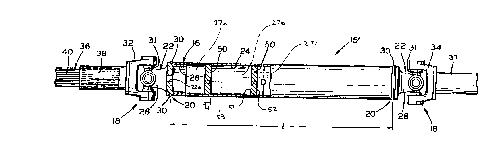
Refening now to Fig. 3, there is illushated a drive line assembly 15' in
acco-dallce with this invention. In general, the drive line assembly 15' includes all of
the components described above. Thelefore, the description of these components and
the numbers used to identify these components are applicable to the description of
dlive line assembly 15'. However, the dlive line assembly 15' in accordance with this
invention has improved sound deadening propelties to reduce noise and vibration from
the driveshaft tube during operation of the vehicle. The invention achieves this benefit
by disposing one or more noise reduction shuctures 50 within the driveshaft tube 16.
It may be desirable to provide several noise reduction shuctures 50 at spaced apart
locations within the dliveshaft tube 16 to address vibration and noise generated by
secondary the harmonics of the resonant frequency.
It has been found to be desirable to folm the noise reduction shuctures 50 from
a polyether material having density of at least 1.4 Ib/ft3, and most desirably are formed
30 having a density of 1.5 Ib/ft3. In a dliveshaft tube 16 having a length of from about 58
CA 02246934 1998-09-11
inches (1473mm) to about 70 inches (1778 mm), it has been found desirable to press
fit a single elongated noise reduction structure 50 therein that is fommed from the
polyether material. The noise reduction structure 50 is preferably about 40 inches
(1016 mm) in length and is centered within the axial length of such a dliveshaft tube
5 16. Altematively, a plurality of separate noise reduction structures 50 may beprovided within the dliveshaft tube 16. It has been found desirable to press fit four of
such noise reduction structures 50 folmed fiom the polyether matelial within thedriveshaft tube 16. Each of the noise reduction stluctures is prefel-ably about 8 inches
(203 mm) in length and are spaced equidistantly apart from one another symmetlically
o within the dliveshaft tube 16. However, the size and number of such noise reduction
structures 50, as well as the matelial used thelein, may be varied as desired.
One of the noise reducing stluctures 50 is illushated in detail in Fig. 4. As
shown therein, the noise reduction structure 50 is a generally cylindlical member
having an axial length Ll extending fi-om a first end 51 to a second end 52. The noise
reduction structure 50 also includes an outer cylindrical surface that defines an outer
diameter D1. Preferably, the outer diameter D 1 of the noise reduction structure 50 is
slightly larger than the inner diameter D of the drivesllaft tube 16. When the outer
diameter D1 is slightly larger than inner diameter D, the noise reduction structure 50
may be press fit within the dliveshaft tube 16. When the noise reduction structure 50
is press fit into the dliveshaft tube 16, it may not be necessaly to use an adhesive to
retain the structure 50 in place. Altematively, any suitable adhesive may be used to
retain the noise reduction structure 50 within the driveshaft tube 16. For example, in a
driveshaft tube 16 having an inner diameter D of about 5.0 inches (127 mm), the noise
reduction structure 50 may have an outer diameter of about 5.115 inches (129.9 mm)
to about 5.135 inches (130.4 mm).
When one or more of the noise reduction structules 50 is disposed within the
driveshaft tube 16, as shown in Fig. 3, a plurality of interior sub-chambers (such as
shown at 27a, 27b, and 27c in Fig. 3) is defined within the driveshaft tube 16. As
shown in Fig. 3, only the first sub-chamber 27a is in direct fluid communication with
30 the vent opening 22a fommed through the tube yoke 22. In order to vent the remaining
CA 02246934 1998-09-11
sub-chambers 27b and 27c to the ahmosphere~ each of the noise reduction shuctures 50
of this invention has a passageway 53 formed th~ luuug~ll. In the preferred
embodiment of the invention illushated in Fig. 4, the paaaa~,~Wa~ 53 is a linear, semi-
circular groove formed in the outer cylindrical surface of the noise reduction shucture
50 that extends between the first and second ends 51 and 52 thereof. However, the
paaaag~wa.y 53 need not extend lineauly and may be formed having any desired cross
sectional shape. Altematively, the paSSdgc~way 53 can be formed partially or
completely within the noise reduction shucture 50, instead of on the outer surface
thereof as illushrated. Also7 a plurality (not shown) of such pâssag~wa.ys 53 may be
formed in each of the noise reduction shuctures 50. The paSSa~;WayS 53 may be
linearly aligned within the driveshaft tube 16 as shown in Fig. 4. However, suchlinear alignment is not necessary. The passageway 53 provides for free air flow from
the first end 51 of the noise reduction shucture 50 to the second 52 thereof. As a
result7 each of the interior sub-chambers 27b and 27c of the driveshaft tube 16 is
properly vented through the vent hole 22a to the atmosphere. As such, the entiredrivesllaft assembly 15' is vented, thereby preventing an undesirable pressurized or
vacuum condition from occulring therein.
In accordance with the provisions of the patent statutes, the principle and modeof operation of this invention have been explained and illushrated in its preferred
embodiment. However, it must be understood that this invention may be practiced
otherwise than as specifically explained and illushrated without depauting from its
spirit or scope.