Language selection

Search

Patent 2247418 Summary

Third-party information liability

Some of the information on this Web page has been provided by external sources. The Government of Canada is not responsible for the accuracy, reliability or currency of the information supplied by external sources. Users wishing to rely upon this information should consult directly with the source of the information. Content provided by external sources is not subject to official languages, privacy and accessibility requirements.

Claims and Abstract availability

Any discrepancies in the text and image of the Claims and Abstract are due to differing posting times. Text of the Claims and Abstract are posted:

  • At the time the application is open to public inspection;
  • At the time of issue of the patent (grant).
(12) Patent: (11) CA 2247418
(54) English Title: ANTENNA FOR A RADIO TELECOMMUNICATIONS DEVICE
(54) French Title: ANTENNE POUR DISPOSITIF DE TELECOMMUNICATIONS PAR VOIE HERTZIENNE
Status: Term Expired - Post Grant Beyond Limit
Bibliographic Data
(51) International Patent Classification (IPC):
  • H01Q 1/08 (2006.01)
  • H01Q 1/10 (2006.01)
  • H01Q 1/22 (2006.01)
(72) Inventors :
  • QI, YIHONG (Canada)
  • JARMUSZEWSKI, PERRY (Canada)
  • EDMONSON, PETER J. (Canada)
  • ZHU, LIZHONG (Canada)
  • CARKNER, STEVEN (Canada)
(73) Owners :
  • RESEARCH IN MOTION LIMITED
(71) Applicants :
  • RESEARCH IN MOTION LIMITED (Canada)
(74) Agent: MARKS & CLERK
(74) Associate agent:
(45) Issued: 2001-01-09
(86) PCT Filing Date: 1997-03-04
(87) Open to Public Inspection: 1997-09-12
Examination requested: 1998-08-27
Availability of licence: N/A
Dedicated to the Public: N/A
(25) Language of filing: English

Patent Cooperation Treaty (PCT): Yes
(86) PCT Filing Number: PCT/CA1997/000155
(87) International Publication Number: WO 1997033338
(85) National Entry: 1998-08-27

(30) Application Priority Data:
Application No. Country/Territory Date
08/611,386 (United States of America) 1996-03-05

Abstracts

English Abstract


A radio telecommunications antenna includes a telescoping antenna portion for
substantially receiving an electromagnetic signal. The telescoping portion is
attached by an antenna mast for conducting the electromagnetic signal. A
dielectric spacer and an inductor are in electrical contact with the antenna
mast. An RF connector is in electrical contact with the dielectric spacer,
opposite the antenna mast, so as to form a capacitor. The RF connector is also
in electrical contact with the inductor so that the capacitor and the inductor
form an LC circuit with values selected to provide a predetermined impedance
match with the remainder of the antenna.


French Abstract

La présente invention concerne une antenne pour télécommunications par voie hertzienne constituée d'une longueur d'antenne télescopique permettant sensiblement de recevoir un signal électromagnétique. La longueur télescopique est raccordée au mât d'antenne de façon à conduire le signal électromagnétique. Un diélectrique intermédiaire et un inducteur sont en continuité galvanique avec le mât d'antenne, un connecteur HF étant en continuité galvanique avec le diélectrique intermédiaire, à l'opposé du mât d'antenne, de façon à constituer un condensateur. Le connecteur HF est également en continuité galvanique avec l'inducteur, ce qui fait que le condensateur forme avec l'inducteur un circuit LC dont les valeurs sont sélectionnées de façon à obtenir une correspondance d'impédances définie avec le reste de l'antenne.

Claims

Note: Claims are shown in the official language in which they were submitted.

-7-
THE EMBODIMENTS OF THE INVENTION IN WHICH AN EXCLUSIVE
PROPERTY OF PRIVILEGE IS CLAIMED ARE DEFINED AS FOLLOWS:
1. An antenna for a radio telecommunications
device comprising:
an antenna portion for substantially receiving
an electromagnetic signal;
antenna circuit components further comprising:
an antenna mast for attaching to the antenna
portion and conducting the electromagnetic signal;
a dielectric spacer in electrical contact with
said antenna mast;
an inductor in electrical contact with said
antenna mast, and in electrical contact with said
dielectric spacer; and
an RF connector in electrical contact with said
dielectric spacer, opposite said antenna mast, so as to
form a capacitor, wherein said RF connector is also in
electrical contact with said inductor so that said
capacitor and said inductor are connected to form an LC
circuit.
2. The antenna of claim 1 wherein the
inductor is received within a hole in the dielectric
spacer.
3. The antenna of claim 1 further including a
spring which applies a mechanical securing force to
retain the dielectric spacer and the inductor in
electrical contact with the antenna mast and the RF
connector.
4. The antenna of claim 1 wherein the RF
connector includes a plurality of posts which secure the
dielectric spacer and provide additional capacitance to
the capacitor.
5. The antenna of claim 4 wherein the posts
are trimmed to desired lengths so as to provide an

-8-
adjustable capacitance.
6. The antenna of claim 5 wherein there are
four posts.
7. The antenna of claim 6 wherein the values
of the inductor and the capacitor are selected so as to
provide an antenna circuit with an impedance that matches
that of the radio telecommunications device.
8. The antenna of claim 1 wherein the values
of the inductor and the capacitor are selected so as to
provide an antenna circuit with an impedance that matches
that of the radio telecommunications device.
9. The antenna of claim 1 wherein the antenna
portion comprises a telescoping antenna portion which can
be varied between minimum and maximum extendible lengths.
10. The antenna of claim 9 wherein the
extendible length of the telescoping antenna portion is
between six and sixteen cm.
11. The antenna of claim 1 wherein the antenna
mast is a hinge which permits the antenna to be pivoted
between O and 90 degrees to the vertical.
12. The antenna of claim 1 further comprising
a housing for receiving and securing the antenna circuit
components into an assembled unit.
13. The antenna of claim 12 wherein the
antenna circuit components are secured with a dielectric
epoxy which provides additional capacitance to the
capacitor.
14. The antenna of claim 1 wherein the antenna
circuit components are secured with a dielectric epoxy
which provides additional capacitance to the capacitor.

-9-
15. The antenna of claim 12 wherein the
assembled unit is pivotable with 360 degrees of rotation.
16. The antenna of claim 1 wherein the antenna
circuit components are compact, thereby reducing the
effect of parasitic capacitance.

Description

Note: Descriptions are shown in the official language in which they were submitted.


CA 02247418 1998-08-27
W 097/33338 PCT/CA97/00155
ANTENNA FOR A RADIO TELECOMMUNICATIONS DEVICE
Background of the Invention
The present invention is directed to the field
of antennas used for radio telecommunications equipment,
particularly those used to transmit and receive a digital
signal r e.g. modems and the like. There has been a
proliferation in recent years in the field of radio
telecommunications with items such as pagers along with
cordless and cellular telephones becoming commonplace
items. Radio modems are also coming into use which
transmit data using a digitally modulated signal. With
such devices, it is very important to maintain a clear,
strong signal which preserves the integrity of the data
transmission.
The various antennas used with existing radio
modems suffer from a number of disadvantages. Previous
radio modem antennas typically suffer from low gain,
resulting in a shorter operating radius and also poor in-
building performance, thus seriously limiting theusefulness of the radio modem.
Previous radio modem antennas are also
sensitive to the presence of a human operator. The human
body inherently retains a quantity of charge and thus
behaves as a capacitor. When a person moves close to the
antenna, their inherent capacitance affects the antenna
current distribution, lowering the gain and detuning the
antenna circuit. This phenomenon is called "parasitic
capacitance" and is also caused by the presence of
certain objects (e.g. metallic bodies) and also various
ground plane conditions.
Previous radio modem antennas are also large
and unwieldy, thus reducing the portability of the
device. Also, previous antennas are fixedly mounted,
having no structures to allow ~or variations in the
operating angle. In these ways, the antennas of previous
systems do not provide the reliable and efficient
operation necessary for the transmission and reception of
a digital signal.
SUBST~TUTE SHEFr (~ULE 26)

CA 02247418 1998-08-27
WO 97/33338 -2- PCT/CA97/001~5
Summary of the Invention
In view of the difficulties and drawbacks
associated with previous antennas, it would be
advantageous to provide an antenna which solves the
previous problems whi~e providing a more reliable and
ef~icient antenna design.
Therefore, there is a need for an antenna with
an increased operating radius.
There is also a need for an antenna with
improved in-building performance.
There is also a need for an antenna which is
less sensitive to the presence of a human operator or
other source of parasitic capacitance.
There is also a need for an antenna which is
small and easily stowed.
There is also a need for an antenna with a wide
range of directional positionability.
These needs and others are realized by the
radio telecommunications antenna of the present invention
which includes an antenna portion for substantially
receiving an electromagnetic signal. The antenna portion
is attached by an antenna mast for conducting the
electromagnetic signal. A dielectric spacer and an
lnductor are in electrical contact with the antenna mast
and respectively in parallel with each other. An RF
connector is in electrical contact with the dielectric
spacer, opposite the antenna mast, so as to form a
capacitor. The RF connector is also in electrical
contact with the inductor so that the capacitor and the
inductor form an LC circuit with values selected to
provide a predetermined impedance match with the
remainder of the antenna.
As will be appreciated, the invention is
capable of other and different embodiments, and its
several details are capable of modifications in various
respect, all without departing from the invention.
Accordingly, the drawings and description are to be
regarded as illustrative in nature and not restrictive.
SUBSTITUTE SHEET (RULE 26~

CA 02247418 1998-08-27
W O g7/33338 -3- PCT/CA97/00155
Brief Description of the Drawings
The embodiments of the invention will now be
described by way of example only, with reference to the
r 5 accompanying figures wherein the members bear like
reference numerals and wherein:
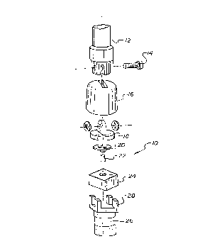
Fig. 1 is an exploded view illustrating the
components and configuration of an antenna circuit as
according to a preferred embodiment of the present
10 invention.
Fig. 2 is a sectional view illustrating the
configuration of the assembled antenna circuit as
according to a preferred embodiment of the present
invention.
Detailed Description of the Invention
Referring now to the drawings which are for
purposes of illustrating only the preferred embodiment of
the present invention and not for purposes of limiting
20 the same, the figures show a monopole antenna having an
LC impedance-matching circuit. The present antenna is
especially suited for transmitting and receiving at 400
to 1000 MHz and can be collapsed down to store within a
modem case that is suitable for inserting within a
25 standard PCMCIA (Personal Computer Memory Card Interface
Association) slot.
Turning specifically to Figs. 1 and 2, the LC
antenna 10 of the present invention includes a
telescoping portion 12 for transmitting and receiving the
30 electromagnetic signal. The telescoping portion 12 is
preferably about six (6) cm. long in its storage position
and can preferably be extended to about 16 cm. long in
its fully-extended operating position. The telescoping
portion is secured to an antenna mast, preferably a metal
35 hinge 18 with a screw 14 and accompanying washers. The
hinge 18 extends upwards through a plastic housing 16
which retains and protects the entire assembled
component.
SUBSTITUTE SHEÇ~ (RUE~ 26)

CA 02247418 1998-08-27
W097133338 -4- PCT/CA97/~015S
The hinge 18 is in contact with a copper spring
20 which applles sufficient force to maintain electrical
contact
through the hinge 18 to the telescoping portion 12. The
spring 20 is in contact with an inductor 22 and a
dielectric spacer 24. The spacer 24 preferably has a
square shape with a central hole and retains the inductor
22 therein as a "lumped" element. The inductor 22 and
the spacer 24 are in electrical contact with an RF
connector 26 which receives the signal conducted through
the antenna 10. The RF connector 26 is connected to the
radio modem assembly and communicates the signal
therethrough. Upon assembly, the base of the assembled
antenna 10 is secured with dielectric epoxy 30 which
holds the components in place against mechanical
disassembly.
The RF connector 26 includes a plurality of
posts 28, preferably four. These posts 28 serve to
retain the dielectric spacer 24 in a secure interference
fit. The RF connector 26 and the metal hinge 18 both
have metallized surfaces which thereby define a capacitor
with the dielectric spacer 24 and the dielectric epoxy
30. The spacer 24 is made of a glass-filled nylon
material having a dielectric constant of about 4. The
epoxy 30 is made from a polymer material having a
dielectric constant of about 4. These materials provide
a capacitor with a desired capacitance.
The capacitor formed by the hinge-spacer-epoxy-
connector sandwich is retained with the inductor 22 so as
to form an LC circuit which matches the impedance of the
antenna
SUBST~TUTE SHEET (~ULE 26

CA 02247418 1998-08-27
W O 97/33338 -5- PCT/CA97/00155
10 to the radio modem. The metallic posts 28 of the RF
connector 26 provide additional capacitance to the
capacitor. The capacitance can be primarily adjusted by
trimming the lengths of the posts 28, which can be
r 5 trimmed to tolerances of a couple thousandths of an inch.
The capacitance can also be secondarily varied by
changing the material of the housing 16, the spacer 24 or
the epoxy 30. In this way, the capacitance can be varied
to a very precise degree. The inductor 22 is preferably
10 a small, high permeability component such as Toko LL 1608
- F22NV, which has a constant inductance of 22
nanohenrys.
By varying the capacitance, the impedance of
the antenna 10 can thus be adjusted to match the measured
15 impedance of the modem. For example, for a 50 ohm radio
modem, the impedance of the antenna can be tuned to 50
ohm. This impedance matching significantly improves the
antenna gain by reducing internal signal reflections in
the circuit. In the radiating mode, the present antenna
20 transmits nearly all the radiant signal, reflecting very
little, as compared with previous systems which lose as
much as half to reflection, transmitting a signal only
hal~ the strength of that generated by the modem. Thus,
the present antenna offers a significant improvement in
25 gain, greatly increasing the effective operating radius
and improving in-building performance.
Another benefit of the present invention is
that the matching circuit is quite small and compact.
This reduces the susceptibility of the antenna to
30 detuning due to parasitic capacitance. The present
antenna can ~unction satis~actorlly in close proximity to
a body, unlike the antennas used with previous systems.
In addition to the above advantages, the
present antenna is small and easily collapsible, allowing
35 easy storage when not in use. Also, when mounted the
antenna can pivot between 0 and 90 degrees off the
vertical plane and also rotate through 360 degrees.
As described hereinabove, the present invention
solves many problems associated with previous antennas,
S~B~TITUTE ~HEEr (RlJLE 26)

CA 02247418 1998-08-27
WO 97/33338 -6- PCT/CA~7/00155
and presents improved efficiency and operability.
However, it will be appreciated that various changes in
the details, materlals and arrangements of parts which
have been herein described and illustrated in order to
explain the nature of the invention may be made by those
skilled in the art within the principle and scope of the
invention as expressed in the appended claims.
SuBsTlTuTE StlEET (RULE 26)

Representative Drawing
A single figure which represents the drawing illustrating the invention.
Administrative Status

2024-08-01:As part of the Next Generation Patents (NGP) transition, the Canadian Patents Database (CPD) now contains a more detailed Event History, which replicates the Event Log of our new back-office solution.

Please note that "Inactive:" events refers to events no longer in use in our new back-office solution.

For a clearer understanding of the status of the application/patent presented on this page, the site Disclaimer , as well as the definitions for Patent , Event History , Maintenance Fee  and Payment History  should be consulted.

Event History

Description Date
Inactive: Expired (new Act pat) 2017-03-04
Grant by Issuance 2001-01-09
Inactive: Cover page published 2001-01-08
Inactive: Final fee received 2000-10-02
Pre-grant 2000-10-02
Notice of Allowance is Issued 2000-05-05
Letter Sent 2000-05-05
Notice of Allowance is Issued 2000-05-05
Inactive: Approved for allowance (AFA) 2000-04-11
Inactive: IPC assigned 1998-11-18
Inactive: First IPC assigned 1998-11-18
Inactive: IPC assigned 1998-11-18
Classification Modified 1998-11-18
Inactive: Inventor deleted 1998-10-27
Inactive: Acknowledgment of national entry - RFE 1998-10-27
Inactive: Inventor deleted 1998-10-27
Application Received - PCT 1998-10-26
Request for Examination Requirements Determined Compliant 1998-08-27
All Requirements for Examination Determined Compliant 1998-08-27
Application Published (Open to Public Inspection) 1997-09-12

Abandonment History

There is no abandonment history.

Maintenance Fee

The last payment was received on 2000-02-23

Note : If the full payment has not been received on or before the date indicated, a further fee may be required which may be one of the following

  • the reinstatement fee;
  • the late payment fee; or
  • additional fee to reverse deemed expiry.

Please refer to the CIPO Patent Fees web page to see all current fee amounts.

Owners on Record

Note: Records showing the ownership history in alphabetical order.

Current Owners on Record
RESEARCH IN MOTION LIMITED
Past Owners on Record
LIZHONG ZHU
PERRY JARMUSZEWSKI
PETER J. EDMONSON
STEVEN CARKNER
YIHONG QI
Past Owners that do not appear in the "Owners on Record" listing will appear in other documentation within the application.
Documents

To view selected files, please enter reCAPTCHA code :


To view images, click a link in the Document Description column. To download the documents, select one or more checkboxes in the first column and then click the "Download Selected in PDF format (Zip Archive)" or the "Download Selected as Single PDF" button.

List of published and non-published patent-specific documents on the CPD .

If you have any difficulty accessing content, you can call the Client Service Centre at 1-866-997-1936 or send them an e-mail at CIPO Client Service Centre.


Document
Description 
Date
(yyyy-mm-dd) 
Number of pages   Size of Image (KB) 
Abstract 1998-08-27 1 48
Description 1998-08-27 6 257
Claims 1998-08-27 3 86
Drawings 1998-08-27 2 40
Cover Page 2000-12-07 2 58
Cover Page 1998-11-24 2 58
Representative drawing 2000-12-07 1 6
Representative drawing 1998-11-24 1 7
Notice of National Entry 1998-10-27 1 201
Courtesy - Certificate of registration (related document(s)) 1998-10-27 1 114
Commissioner's Notice - Application Found Allowable 2000-05-05 1 164
PCT 1998-08-27 9 291