Note: Descriptions are shown in the official language in which they were submitted.
CA 02247745 2002-04-23
76140-71
1
NITRIC OXIDE ENHANCED
RESPONSE CIRCUIT FOR GAS ANALYZER
Cross-Reference to Related Application
This application claims the benefit of U.S. patent no.
6,082,177.
Background of the Invention
The present invention relates generally to test and
diagnostic equipment for testing motor vehicles,
particularly vehicles powered by internal combustion
engines. The invention has particular application to
diagnostic equipment incorporating gas analyzers for
analyzing exhaust emissions from internal combustion
engines, and even more specifically to nitric oxide (NO)
sensor circuits for such gas analyzers.
The present invention ~is an improvement of a NO
sensing circuit of the type used with a diagnostic system,
such as that sold by Sun Electric and known as a Service
Inspection System. That system includes an infrared (IR)
shelf assembly module, which includes a non-dispersive
infrared (NDIR) optical bench which detects the
concentration of hydrocarbons, carbon monoxide, carbon
dioxide and other gases within the vehicle exhaust system.
The NDIR optical bench includes optional input/output
circuits and peripheral transducers for additional inputs,
including a NO input.
There are government regulations setting forth
specifications for the performance of engine diagnostic
equipment and, in particular, emissions analyzers. Among
these specifications is a response time specification for
certain gas constituent sensors. The specifications
CA 02247745 1998-09-21
2
essentially require that the sensor output reach a certain
percentage of a nominal output reading within a certain time
period, e.g., within four or five seconds, the specified
time period varying with the ambient temperature at which
the test is conducted. Applicants have found that when the
:10 sensor was utilized in an emissions analyzer, _ts
response times, i.e., the rise and fall times of the sensor
output, could exceed the specifications set by government
regulations, particularly at low ambient temperatures.
Applicants attempted heating the NO sensing cell, as with a
resistive heater, but the heater did not decrease response
times enough to meet specifications.
Summary of the Invention
It is a general object of the present invention to
provide an improved fluid constituent detection apparatus
which avoids the disadvantages of prior apparatus while
affording additional structural and operating advantages.
An important feature of the invention is the provision
of a sensing circuit for a gas constituent which provides
relatively fast response times.
In connection with the foregoing feature, another
feature of the invention is the provision of a sensing
circuit of the type set forth, which does not require any
auxiliary heating.
Still another feature of the invention is the provision
of a sensing circuit of the type set forth which is
temperature responsive, so as tQ_alter operation of the
circuit depending upon ambient temperature.
CA 02247745 2002-04-23
76140-71
3
Certain ones of these and other features of the
invention may be attained by providing apparatus for
analyzing exhaust emissions from an internal combustion
engine comprising: a transducer assembly including an
electrochemical sensor responsive to an oxide of nitrogen in
the emissions for generating an electrical output signal at
an output, a processing circuit having an input and
responsive to the output signal, and a response enhancing
circuit adapted to be coupled in series between said output
and said input for reducing the duration of said output
signal whereby the overall response time of the apparatus is
reduced.
Other features of the invention may be attained by
providing fluid constituent detection apparatus having an
output terminal and comprising: a transducer responsive to
a predetermined constituent of a fluid for generating an
electrical output signal at a transducer output, a response
enhancing circuit adapted to be coupled to said transducer
output for reducing the duration of the output signal, and a
switch mechanism having a first condition for electrically
connecting said response enhancing circuit in series between
said transducer output and said output terminal and a second
condition for electrically disconnecting said response
enhancing circuit from said output terminal and connecting
said transducer output directly to said output terminal.
Still other features of the invention may be
attained by providing a method for sensing a constituent gas
in the exhaust emissions of an internal combustion engine
comprising: exposing the emissions to a constituent
transducer for producing an electrical output signal
indicative of the presence of the constituent gas, sensing
the ambient temperature, and reducing the duration of the
CA 02247745 2002-04-23
'76140-71
3a
output signal only when the ambient temperature is below a
predetermined temperature.
The invention consists of certain novel features
and a
CA 02247745 1998-09-21
4
combination of parts hereinafter fully described and
illustrated in the accompanying drawings, it being
understood that various changes in the details may be made
without departing from the spirit, or sacrificing any of the
advantages of the present invention.
Brief Description of the Drawings
For the purpose of facilitating an understanding of the
invention, there is illustrated in the accompanying drawings
a preferred embodiment thereof, from an inspection of which,
when considered in connection with the following
description, the invention, its construction and operation,
and many of its advantages should be readily understood and
appreciated.
FIG. 1 is a partially schematic and partially
functional block diagrammatic view of a gas analyzer for a
service inspection system of the type with which the present
invention is intended to be used;
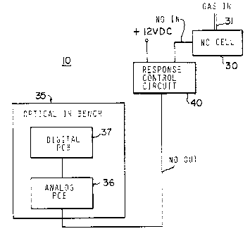
FIG. 2 is a block diagram of a pertinent portion of the
gas analyzer of FIG. 1, illustrating the location of the
sensor response control circuit of the present invention;
FIG. 3 is a schematic diagram of the sensor response
control circuit of the present invention; and
FIGS. 4 and 5 are graphs illustrating the effect of the
response control circuit of FIG. 3.
Description of the Preferred Embodiment
Referring to FIG. 1 there is illustrated a sensor or
transducer assembly of a prior art exhaust analyzer 10 of
the type with which the present invention is intended to be
CA 02247745 1998-09-21
used, including an optical IR bench 35 and a nitric oxide
cell 30, which is an electrochemical cell transducer or
sensor and produces an electrical output indicative of the
amount of nitric oxide in the gas sample.
5 More specifically, the optical IR bench 35 includes gas
sample tubes 1i, 12 and 13 which may, respectively, be
designed for sensing carbon monoxide (CO), hydrocarbons (HC)
and carbon dioxide (COz). The sample tube 12 communicates
with each of the other sample tubes 11 and 13, and the
sample tube 11 also communicates with a gas inlet conduit
14, which is adapted to be coupled to receive the exhaust
emissions from an associated internal combustion engine (not
shown) under test, while the sample tube 13 is coupled to a
gas outlet conduit 15. The sample tubes 11-13 are,
respectively, provided with infrared (IR) sources 16-18,
respectively located at one end of the tubes 11-13 for
radiating infrared energy through the tubes, the sources 16-
18 being coupled to an associated DC voltage source
through a switch assembly 19 operated by a switch control
circuit 19a. Preferably, the IR sources 16-18 are duty
cycle controlled (chopped) to provide an ON/OFF reference
state for each IR sensor. The optical IR bench 35 also
includes an optical filter/ detector assembly 20, which
includes three detectors 21, 22 and 23, respectively
provided at the ends of the sample tubes 11-13 cpposite the
IR sources 16-13, and four associated optical filters 24-27.
LZore particularly, the CO and COz sample tubes 11 and 13,
respectively, nave optical filters 24 and 27, while the HC
CA 02247745 1998-09-21
sample tube 12 has two optical filters, a reference filter -
25 and an HC filter 26.
It will be appreciated that the gases inside the sample
tubes 11-13 absorb the IR energy as it passes therethrough,
and the detectors convert the received IR energy into a
voltage output signal, which is chopped because the input
voltage to the IR sources is chopped. The outputs of the
optical filters 24-27 are applied through an amplifier
circuit 28 and, after digital conversion at 29, are applied
to a microprocessor 34 which analyzes the output signals and
also controls the switch control circuit 19a. The output of
the NO cell 30 is also provided to the amplifier circuit 28
of the optical IR bench 35.
It is a fundamental aspect of the present invention
that a response control circuit 40 is interposed between the
NO cell 30 and the optical IR bench 35, as shown in FIG. 2.
The details of the response control circuit 40 are shown in
FIG. 3. The NO cell 30 has an inlet conduit 31, which
communicates with the gas inlet conduit 14, and generates an
electrical output signal indicative of the presence of a
nitric oxide constituent in the inlet emissions gases, which
output is also applied to the amplifier circuit 28 as signal
"NO IN". The NDIR optical bench 35 also includes a
temperature sensor 32 and a pressure sensor 33 coupled to
the gas outlet conduit 15 and producing electrical output
signals which, are in turn, coupled to the amplifier circuit
28. Preferably, the amplifier circuit 28 and the switch
control circuit 19a are located on an analog printed circuit
CA 02247745 1998-09-21
7
board 36, while the analog-to-digital conversion circuitry
29 and the microprocessor 34 are located on a digital
printed circuit board 37. In accordance with the present
invention the Pd0 IN signal from the NO cell 30 is applied to
the response control circuit 40, the output of which,
designated "ri0 OUT" is applied to the amplifier circuit 28
on the analog PCB 36.
Referring to FIG. 3, the response control circuit 40
includes a response-enhancing circuit 41. In particular,
the NO IN signal from the NO cell 30, is applied through a
parallel R-C circuit, including a resistor 42 and a
capacitor 43, to the non-inverting input of an operational
amplifier (op amp) 44, which may be a TLC252C, which input
is also connected through a resistor 45 to ground. The
output of the op amp 44 is connected through a resistor 46
to its inverting input, which input is also connected
through a resistor 47 to ground. The output of the op amp
44 is also connected through a resistor 48 to one input (S8)
of an analog nultiplexer 50, which may be a ADG508A. The NO
IN signal is also connected directly to the S1 input of the
multiplexes 50, these two inputs being respectively
connected to the NO OUT terminal D of the multiplexes 50
through normally-open switch paths 51 and 52, the selection
of which path is closed being determined by the signals on
the A0, A1 and A2 inputs. The multiplexes 50 also has an
enable input connected through a resistor 53 to a +5 VDC
supply and VSS and VDD inputs respectively connected to V-
and V+ supplies.
CA 02247745 1998-09-21
a
Thus, it will be appreciated that the R-C circuit
provided by the resistor 42 and capacitor 43 is normally
connected to the NO OUT output. In operation, the R-C
circuit provides a time constant and the resistor 42
cooperates with the resistor 45 to provide a voltage
divider, this circuitry serving to reduce the rise and fall
times of the response of the NO cell 30. Because of the
reduction of voltage at the input of the op amp 44 by reason
of the voltage divider, the op amp 44 cooperates with the
resistors 46 and 47 to provide a suitable amplification,
preferably about 1.15.
A temperature-responsive control circuit 60 for the
multiplexer 50 includes an op amp 61, which may be an LM311,
configured as a comparator, which has its non-inverting
input connected to the junction between resistors 62 and 62A
of a voltage divider, which is connected between ground and
the cathode of a Zener diode 63, the anode of which is
grounded. The cathode of the Zener diode 63 is also
connected through a resistor 64 to the +5 VDC supply. The
output of the comparator op amp 61 is connected to its non-
inverting input through a resistor 65. The resistor 62 sets
a reference voltage level corresponding to a predetermined
ambient temperature level, which may be about 80° F. The
inverting input of the comparator 61 is connected to a
temperature sensor 66, which senses the ambient temperature
and outputs an electrical signal indicative of that
temperature. The inverting and non-inverting inputs of the
op amp 51 are also respectively connected to ground through
CA 02247745 1998-09-21
9
filter capacitors 67 and 67a.
When the sensed ambient temperature exceeds the
reference temperature level, the comparator switches to
produce an output signal, applied through a resistor 71 to
the A0, A1 and A2 inputs of the multiplexes 50 to switch its
condition, thereby opening the path 51 and closing the path
52 so that the NO IN signal is connected directly to the NO
OUT terminal, thus effectively removing the response-
enhancing circuit 41 from the circuit. This switching will
also be visually indicated by illumination of an LED 68,
which is powered from a +5 VDC supply through a voltage
divider 69 provided by resistors 69a and 69b. The +5 VDC
supply is obtained from a voltage regulator 70, which may be
an LM7805. The V+ and V- supply voltages are provided from
an external source and are applied to the op amp 44 and
to the multiplexes 50, and the V+ supply is applied to the
op amp 61, all of these supplies being provided with
suitable bypass capacitors.
In operation, the R-C response-enhancing circuit 41
serves to reduce the rise and fall times of the response of
the NO cell 30 to levels well within the specifications
provided by pertinent government regulations. However, it
has been found that, at ambient temperatures above a certain
level, typically approximately 80° F, the response time
enhancement provided by the R-C network is unnecessary and,
indeed, may result in overshoot of the intended output
voltage level of the sensor circuitry. Thus, the control
circuit 60 serves to automatically remove the R-C network
CA 02247745 1998-09-21
from the response control circuit 40 when the ambient -
temperature reaches the predetermined temperature level and
will, likewise, switch it back into the circuit when the
ambient temperature falls below that predetermined level.
5 Referring now to FIG. 4, there is illustrated a
waveform 75 representative of the response of the NO cell 30
without the enhancement circuit of the present invention.
The waveform 75 has a rising portion 76, which rises from an
initial value of -2 volts to a maximum output value of
10 approximately +1.8 volts, i.e., a total rise of 3.8 volts.
Similarly, after disconnection from the exhaust emissions,
the response falls back to the initial zero-emissions level
during a fall period 77 of the waveform. The rise time of
the waveform 75 is calculated as the time required to rise
from the essentially zero-emissions starting point to 90% of
the maximum output value, while the fall time is the time
required to drop from the maximum output value to
approximately 10% of that value. The rise time is indicated
in FIG. 4 as the time from t1 to t2, which was calculated to
be 5.072 seconds, while the fall time from t3 to t4 was
calculated at 5.576 seconds, with all measurements taken at
40°F.
Referring to FIG. 5, there is illustrated the
corresponding waveform 75A utilizing the response-enhancing
circuit of the present invention. In this case, the rising
portion 76A of the waveform has a rise time from t1 to t2
calculated at 2.416 seconds, while the falling portion 77A
has a fall time from t3 to t4 calculated at 3.126 seconds.
CA 02247745 1998-09-21
11
Thus, the response time of the NO cell has been nearly cut
in half by the use of the present invention.
In a constructional model of the present invention, the
op amp 44 may be a TLC252 CP, the comparator op amp 61 may
be an LM311, the Zener diode 63 may be an LM336, the
temperature sensor 66 may be an LM34C and the voltage
regulator 70 may be a 7805. It will be appreciated that the
values of the resistors 42 and 45-48 and the capacitor 43
will vary depending upon the amount of speed-up of the NO
cell response that is desired. Similarly, the values of the
components of the control circuit 60 will vary depending
upon the ambient temperature at which switching is desired.
From the foregoing, it can be seen that there has been
provided gas sensor circuitry which provides an enhanced
response time and automatically removes the enhancement when
it is not needed.
While particular embodiments of the present invention
have been shown and described, it will be obvious to those
skilled in the art that changes and modifications may be
made without departing from the invention in its broader
aspects. The matter set forth in the foregoing description
and accompanying drawings is offered by way of illustration
only and not as a limitation.