Language selection

Search

Patent 2247785 Summary

Third-party information liability

Some of the information on this Web page has been provided by external sources. The Government of Canada is not responsible for the accuracy, reliability or currency of the information supplied by external sources. Users wishing to rely upon this information should consult directly with the source of the information. Content provided by external sources is not subject to official languages, privacy and accessibility requirements.

Claims and Abstract availability

Any discrepancies in the text and image of the Claims and Abstract are due to differing posting times. Text of the Claims and Abstract are posted:

  • At the time the application is open to public inspection;
  • At the time of issue of the patent (grant).
(12) Patent: (11) CA 2247785
(54) English Title: MOLDS FOR A CONTINUOUS CASTING SYSTEM
(54) French Title: MOULES POUR SYSTEME DE COULEE EN CONTINU
Status: Expired and beyond the Period of Reversal
Bibliographic Data
(51) International Patent Classification (IPC):
  • B22C 9/06 (2006.01)
  • B22D 11/04 (2006.01)
  • B22D 11/055 (2006.01)
  • B22D 11/059 (2006.01)
(72) Inventors :
  • RODE, DIRK (Germany)
  • VILLANUEVA, HECTOR (Germany)
(73) Owners :
  • KME GERMANY GMBH & CO. KG
(71) Applicants :
  • KME GERMANY GMBH & CO. KG (Germany)
(74) Agent: G. RONALD BELL & ASSOCIATES
(74) Associate agent:
(45) Issued: 2002-11-26
(22) Filed Date: 1998-09-18
(41) Open to Public Inspection: 1999-04-25
Examination requested: 1998-11-26
Availability of licence: N/A
Dedicated to the Public: N/A
(25) Language of filing: English

Patent Cooperation Treaty (PCT): No

(30) Application Priority Data:
Application No. Country/Territory Date
197 47 305.9 (Germany) 1997-10-25

Abstracts

English Abstract


The invention concerns a mold for a continuous casting system
with a shaping mold tube made of a material with high thermal
conductivity. To reduce the rate of heat removal at the height
of the meniscus that forms within the mold cavity, the
exterior of the mold tube is provided with a plating of a
material of lower thermal conductivity than that of the mold
tube. This results in reduced heat flow with higher
temperatures in the meniscus area and in improvement in the
surface quality of the cast billet.


French Abstract

L'invention a trait à un moule pour un système de coulée en continu comprenant un tube de moule fait d'un matériau d'une grande conductivité thermique. Pour réduire le taux d'évacuation de chaleur à la hauteur du ménisque qui se forme à l'intérieur de la cavité du moule, l'extérieur du tube de moule est recouvert d'un matériel d'une conductivité thermique inférieure à celle du tube, ce qui permet de réduire le flux thermique lorsque les températures sont plus élevées dans la zone du ménisque et d'améliorer la qualité de la surface de la billette coulée.

Claims

Note: Claims are shown in the official language in which they were submitted.

THE EMBODIMENTS OF THE INVENTION IN WHICH AN EXCLUSIVE PROPERTY
OR PRIVILEGE IS CLAIMED ARE DEFINED AS FOLLOWS:
1. A mold for a continuous casting system, comprising:
a shaping mold body made of a material having a high level
of thermal conductivity, the mold body having an outer surface
and an inner surface;
at least one plating of a material having a lower level of
thermal conductivity than the material of the mold body, the
plating being located along the outer surface of the mold body
and applied at the height of a meniscus that forms in the mold
cavity when it is charged with a stream of molten material.
2. A mold as set forth in claim 1, wherein the plating is
applied along a portion of the circumferential extent of the mold
body.
3. A mold as set forth in claim 1 or 2, wherein the plating is
applied by electroplating.
4. A mold as set forth in claim 1 or 2, wherein the plating is
applied as a thermal spray layer.
5. A mold as set forth in any one of claims 1 to 4, wherein the
plating is made of nickel or an alloy of nickel.
6. A mold as set forth in any one of claims 1 to 5, wherein the
mold body defines a casting direction, and the plating has a
constant thickness in the casting direction.
7. A mold as set forth in any one of claims 1 to 5, wherein the
mold body defines a casting direction, and the plating has a
thickness that diminishes in the casting direction.
11

8. A mold as set forth in any one of claims 1 to 7, wherein the
mold body has plating along its inner surface.
9. A mold as set forth in claim 7, wherein the plating has a
maximum thickness of 3 mm.
10. A mold as set forth in claim 7 or 9, wherein the plating
tapers in thickness to 1 mm.
11. A mold as set forth in claim 7, 9 or 10, wherein the plating
varies linearly in thickness.
12. A mold as set forth in any one of claims 1 to 11, wherein
the mold is made of copper.
13. A mold as set forth in any one of claims 1 to 11, wherein
the mold is made of an alloy of copper.
12

Description

Note: Descriptions are shown in the official language in which they were submitted.


- CA 02247785 1998-09-18
MOLDS FOR A CONTINUOUS CASTING SYSTEM
Background of the Invention
This invention concerns a mold for a continuous casting
system having a shaping mold body made of a material that has
a high level of thermal conductivity, such as copper or a
copper alloy.
Molds are used for establishing the profiles of solids
that are manufactured in a continuous casting process. The
mold is one of the most important components of a continuous
casting system, as the melt begins solidifying while within
it.
The mold design, in general, includes an outer steel
construction. The actual shaping component of the mold is the
mold body. Mold bodies are today made almost exclusively of
copper or a copper alloy. The function of the steel jacket is
to position the mold body and to provide the water circulation
required for cooling.

CA 02247785 1998-09-18
In order to protect it against wear, the mold body is
typically provided with an internal plating made of a wear-
resistant material such as nickel or chromium. An example of
such a continuous casting mold with wear-resistant coating is
described in German Patent No. 31 42 196 C2. The friction
characteristics and therefore the service life of the mold
body can be improved in this manner.
As liquid steel cools while flowing through the mold
body, it solidifies in the outer areas, forming a billet layer
with a continuously growing thickness. The cross-sectional
geometry of the billet changes by shrinking.
Thus, in addition to shaping the billet, the mold body
also has the important function of ensuring the formation of a
sufficiently thick, high-strength and defect-free billet layer
through the continuous removal of heat.
Excessive heat removal and cooling of the steel melt at
the beginning of the solidification process, particularly in
the meniscus area, negatively affects the billet surface
quality. It may result in microcracks in the surface and
microstructure defects. These are formed mainly near the edges
2

- ' ' CA 02247785 1998-09-18
of the mold body. Furthermore, there is a danger of the billet
becoming seized in the tapering mold body.
In order to reduce heat removal in the meniscus area, the
method of electromagnetically agitating the melt in the mold
body is known. This method is, however, relatively expensive.
Furthermore, attempts have been made to reduce heat removal
using vertical slots in the internal wall of the mold body or
inserts made of refractory material.
Tests with thicker internal wear-protection platings have
also been conducted. Due to the difference in heat elongation
coefficients of the mold body (mainly copper) and the wear-
resistant plating (mainly nickel), considerable stresses
appear in the wear-resistant plating. Adherence is negatively
affected and cracks may form.
There remains a need to provide a mold body where heat
removal, particularly in the meniscus area, is reduced and
better billet quality is achieved.
3

CA 02247785 2001-12-20
summary of the Invention
The present invention addresses this need by providing a
mold for a continuous casting system, in which the mold body
S is made of a material having a high level of thermal
conductivity, and is plated along its outer surface with a
coating of a material that has a lower level of thermal
conductivity than the material of the mold body. A central
concern of the present invention is the reduction of the rate
of heat removal from the mold body by using an outer plating.
Since the coating or plating is made of a material having a
low degree of heat conductivity compared with the mold body
material, there results a reduced level of heat flow in the
meniscus area, which is the process engineering objective
addressed by this invention. The resulting higher temperatures
have a positive effect on the billet surface quality and
microstructure quality.
According to an aspect of the present invention there is
provided a mold for a continuous casting system, comprising a
shaping mold body made of a material having a high level of
thermal conductivity, the mold body having an outer surface
and an inner surface; at least one plating of a material
having a lower level of thermal conductivity than the material
4

CA 02247785 2001-12-20
of the mold body, the plating being located along the outer
surface of the mold body and applied at the height of a
meniscus that forms in the mold cavity when it is charged with
a stream of molten material.
The mold bodies used with this invention can essentially
be single-piece or multi-piece molds, e.g., a plate mold.
Even when it is possible to fully plate the mold body
externally, plating is advantageously applied only at the
4a

CA 02247785 1998-09-18
height area of the meniscus. This allows selective reduction
of heat removal in the meniscus area, so that the strength of
the billet shell is not exceeded.
The thickness and length of the outer plating is adjusted
to the casting and plant parameters in each case.
According to one variant of the invention, plating is
only applied along a portion of the mold body perimeter. This
measure is particularly recommended in the case of non-
symmetrical mold bodies. For example, in the case of
adjustable molds, it can be advantageous to only provide the
longitudinal plates with an outer plating.
Disproportionate shrinking of the billet in certain
areas, (e. g., in the corner areas) can be avoided through
selective plating. This ensures that heat transfer is
approximately uniform over the entire perimeter of the billet,
so that a uniformly growing billet shell thickness is achieved
over the entire cross-section of the billet.
High-quality and cost-effective plating can be applied
electrically. The plating can also be applied by thermal
5

CA 02247785 1998-09-18
spraying a thermal spray layer.
The plating used may be made of nickel or a nickel alloy.
Nickel materials have been successfully used as internal wear-
protection platings. Therefore users also often have the
resources to nickel plate mold bodies.
Nickel has a heat conductivity that is more than four
times lower than that of copper. Accordingly, effective
reduction of heat removal and thus increase in temperature in
the meniscus area is achieved by nickel plating on the
outside.
Nickel can be applied either via electroplating or as a
metallic spray coating. It is within the scope of the
invention to plate the outer surface of the mold body either
fully or only locally in the meniscus area.
According to one embodiment of the invention, the plating
has a constant thickness in the direction of casting. The
transitions in the plating edge areas are continuous, thus
avoiding local concentrations of stresses.
6

CA 02247785 1998-09-18
According to another embodiment of the invention, the
shrinkage characteristics of the material to be cast can be
selectively taken into account by using a plating, in which
the thickness diminishes in the direction of casting. In this
case, heat removal increases in the direction of casting. In
this manner, the amount of cooling available for
solidification in the mold can be effectively optimized with
regard to the shrinkage characteristics of the billet.
The thickness of the external plating may diminish
linearly or stepwise.
Since copper and copper alloys, used as mold body
materials, have relatively low wear-resistance, it may prove
convenient, depending on the application, to provide the mold
body with an internal plating in the known manner. Internal
platings made of nickel, chromium, or chrome-plated nickel
have been successfully used as internal platings.
Brief Description of the Drawings
The invention will be described in detail below with
reference to the embodiments illustrated in the drawings.
7

CA 02247785 1998-09-18
Figures 1 through 3 each provide a vertical cross-
sectional view of an embodiment of a mold body in the shape of
a mold tube constructed according to the principles of the
invention.
Detailed Description
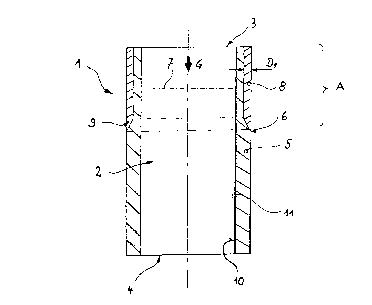
Figure 1 shows a mold tube 1 for the continuous casting
of steel. Mold tube 1 has a mold cavity 2, whose cross-section
is larger at the front, pour-in end 3 than at the rear, billet
removal end 4.
Base body 5 of mold tube 1 is made of a copper alloy,
preferably a copper/chromium zirconium-based alloy (CuCrZr).
On its exterior surface 6, the mold tube 1 has a plating 8 on
a part A at the height of the meniscus 7. The plating 8 is
made of a material that has a lower heat conductivity compared
to the material of the mold tube 1 or base body 5. Nickel is
particularly well-suited as the material for the external
plating 8. Nickel can be applied either as electroplating or
as a thermal spray layer.
Plating 8 reduces the heat flow and therefore heat
removal from mold tube 1 at the height of the meniscus 7. This
8

CA 02247785 1998-09-18
results in higher wall temperatures in the initial phase of
billet shell formation and in improved steel billet surface
quality. In particular, microcracks near the edges of mold
tube 1 can thus be prevented.
As can be seen in Figure 1, plating 8 has an
approximately constant thickness D1 in the direction of casting
G. In the transition area 9, the thickness of plating 8
diminishes continuously toward the outer surface 6.
Along the interior surface 10, the mold tube 1 is
provided with a wear-protection plating 11 of chromium, which
is approximately 80 ~m thick.
Another embodiment of a mold tube 12 is illustrated in
Figure 2. On the pour-in side 13 it has external plating 14 to
reduce heat removal. Plating 14 extends over the area of the
height of meniscus 15, with thickness DZ of plating 14
diminishing in the casting direction G. One possible
embodiment of plating 14 provides for a thickness D2
diminishing from 3 mm to 1 mm with a continuous transition
area 16 at the end.
9

CA 02247785 1998-09-18
Figure 3 shows a section of another variant of a mold
tube 17. Mold tube 17 has plating 18 on the outside 19, whose
thickness D3 diminishes linearly from front end 20 to rear end
21. The heat removal is reduced in mold tube 17 by plating 18.
The heat flow, however, increases overall from front end 20 of
the mold tube to rear end 21.
The mold body of a mold according to the present
invention does not necessarily have to be a mold tube. The
invention is equally advantageous for multipart casting molds
such as plate molds.

Representative Drawing
A single figure which represents the drawing illustrating the invention.
Administrative Status

2024-08-01:As part of the Next Generation Patents (NGP) transition, the Canadian Patents Database (CPD) now contains a more detailed Event History, which replicates the Event Log of our new back-office solution.

Please note that "Inactive:" events refers to events no longer in use in our new back-office solution.

For a clearer understanding of the status of the application/patent presented on this page, the site Disclaimer , as well as the definitions for Patent , Event History , Maintenance Fee  and Payment History  should be consulted.

Event History

Description Date
Time Limit for Reversal Expired 2017-09-18
Letter Sent 2016-09-19
Letter Sent 2015-10-20
Inactive: Multiple transfers 2015-08-31
Inactive: IPC from MCD 2006-03-12
Grant by Issuance 2002-11-26
Inactive: Cover page published 2002-11-25
Pre-grant 2002-07-18
Inactive: Final fee received 2002-07-18
Amendment After Allowance Requirements Determined Compliant 2002-07-11
Letter Sent 2002-07-11
Amendment After Allowance (AAA) Received 2002-05-17
Notice of Allowance is Issued 2002-01-30
Letter Sent 2002-01-30
Notice of Allowance is Issued 2002-01-30
Inactive: Approved for allowance (AFA) 2002-01-21
Amendment Received - Voluntary Amendment 2001-12-20
Inactive: S.30(2) Rules - Examiner requisition 2001-06-22
Inactive: Cover page published 1999-05-21
Application Published (Open to Public Inspection) 1999-04-25
Amendment Received - Voluntary Amendment 1999-04-13
Letter Sent 1998-12-22
Inactive: Single transfer 1998-11-27
All Requirements for Examination Determined Compliant 1998-11-26
Request for Examination Requirements Determined Compliant 1998-11-26
Request for Examination Received 1998-11-26
Inactive: IPC assigned 1998-11-24
Classification Modified 1998-11-24
Inactive: IPC assigned 1998-11-24
Inactive: First IPC assigned 1998-11-24
Inactive: Courtesy letter - Evidence 1998-11-10
Inactive: Filing certificate - No RFE (English) 1998-11-06
Filing Requirements Determined Compliant 1998-11-06
Application Received - Regular National 1998-10-30

Abandonment History

There is no abandonment history.

Maintenance Fee

The last payment was received on 2002-09-11

Note : If the full payment has not been received on or before the date indicated, a further fee may be required which may be one of the following

  • the reinstatement fee;
  • the late payment fee; or
  • additional fee to reverse deemed expiry.

Please refer to the CIPO Patent Fees web page to see all current fee amounts.

Owners on Record

Note: Records showing the ownership history in alphabetical order.

Current Owners on Record
KME GERMANY GMBH & CO. KG
Past Owners on Record
DIRK RODE
HECTOR VILLANUEVA
Past Owners that do not appear in the "Owners on Record" listing will appear in other documentation within the application.
Documents

To view selected files, please enter reCAPTCHA code :


To view images, click a link in the Document Description column. To download the documents, select one or more checkboxes in the first column and then click the "Download Selected in PDF format (Zip Archive)" or the "Download Selected as Single PDF" button.

List of published and non-published patent-specific documents on the CPD .

If you have any difficulty accessing content, you can call the Client Service Centre at 1-866-997-1936 or send them an e-mail at CIPO Client Service Centre.


Document
Description 
Date
(yyyy-mm-dd) 
Number of pages   Size of Image (KB) 
Description 2001-12-20 11 273
Claims 2001-12-20 2 52
Cover Page 2002-10-24 1 31
Description 1998-09-18 10 255
Abstract 1998-09-18 1 15
Drawings 1998-09-18 1 15
Claims 1998-09-18 3 60
Representative drawing 1999-05-19 1 5
Cover Page 1999-05-19 1 38
Filing Certificate (English) 1998-11-06 1 163
Acknowledgement of Request for Examination 1998-12-22 1 177
Courtesy - Certificate of registration (related document(s)) 1999-01-07 1 115
Reminder of maintenance fee due 2000-05-23 1 111
Commissioner's Notice - Application Found Allowable 2002-01-30 1 164
Courtesy - Certificate of registration (related document(s)) 2015-10-20 1 102
Maintenance Fee Notice 2016-10-31 1 177
Correspondence 2002-07-18 1 25
Correspondence 1998-11-10 1 31
Fees 2001-09-10 1 44
Fees 2002-09-11 1 36
Fees 2000-09-11 1 46