Language selection

Search

Patent 2248683 Summary

Third-party information liability

Some of the information on this Web page has been provided by external sources. The Government of Canada is not responsible for the accuracy, reliability or currency of the information supplied by external sources. Users wishing to rely upon this information should consult directly with the source of the information. Content provided by external sources is not subject to official languages, privacy and accessibility requirements.

Claims and Abstract availability

Any discrepancies in the text and image of the Claims and Abstract are due to differing posting times. Text of the Claims and Abstract are posted:

  • At the time the application is open to public inspection;
  • At the time of issue of the patent (grant).
(12) Patent: (11) CA 2248683
(54) English Title: UNDERWATER INSTALLATION AND METHOD FOR BUILDING OF AN UNDERWATER INSTALLATION
(54) French Title: INSTALLATION SOUS-MARINE ET SON PROCEDE DE CONSTRUCTION
Status: Expired and beyond the Period of Reversal
Bibliographic Data
(51) International Patent Classification (IPC):
  • E21B 43/013 (2006.01)
  • E21B 7/132 (2006.01)
  • E21B 43/01 (2006.01)
  • E21B 43/017 (2006.01)
(72) Inventors :
  • MAGNUSSEN, TERJE (Norway)
(73) Owners :
  • MEPS-FIRST OIL LTD.
(71) Applicants :
  • MEPS-FIRST OIL LTD. (Cyprus)
(74) Agent: MARKS & CLERK
(74) Associate agent:
(45) Issued: 2006-04-18
(86) PCT Filing Date: 1997-03-07
(87) Open to Public Inspection: 1997-09-18
Examination requested: 2001-10-18
Availability of licence: N/A
Dedicated to the Public: N/A
(25) Language of filing: English

Patent Cooperation Treaty (PCT): Yes
(86) PCT Filing Number: PCT/NO1997/000068
(87) International Publication Number: WO 1997034074
(85) National Entry: 1998-09-10

(30) Application Priority Data:
Application No. Country/Territory Date
960997 (Norway) 1996-03-12

Abstracts

English Abstract


An underwater installation for use in offshore drilling of and production
from,
respectively, oil and/or gas wells at deep and moderate deep water comprises
an
intermediate station in the form of a buoyancy based hollow body (16) tension
strut
anchored at the seabed (10) and located at a depth substantially closer to the
surface
of the sea than the seabed (10). At least one hydrocarbon conveying pipeline
extends
between the buoyancy body (16) and seabed depth, for the transfer of
hydrocarbons from
the reservoir to said buoyancy body (16). At least one casing liner string
(18a-18h)
constitutes the tension leg/strut anchoring of the buoyancy body (16). The
invention
also relates to a method for the building of an underwater installation.


French Abstract

Installation sous-marine à utiliser dans le forage offshore et l'exploitation, respectivement, de puits de pétrole en eau profonde et moyennement profonde. Ladite installation comporte une station intermédiaire se présentant sous la forme de jambes de force d'un corps creux flottant (16), ancrées dans le fond marin (10) et situées à une profondeur sensiblement plus proche de la surface de la mer que du fond (10). Au moins un pipeline de transport d'hydrocarbures s'étend entre le corps flottant (16) et le fond marin pour le transfert d'hydrocarbures depuis le réservoir jusqu'audit corps flottant (16). Au moins un train de chemises du tubage (18a-18h) constitue l'ancrage formant jambe de force du corps flottant (16). L'invention concerne aussi un procédé de construction d'une installation sous-marine.

Claims

Note: Claims are shown in the official language in which they were submitted.

5
The embodiments of the invention in which an exclusive
property or privilege is claimed are defined as follows:
1. An underwater installation for offshore
drilling of a hydrocarbon well or wells in the seabed for
the production of hydrocarbons from a reservoir below the
seabed, the well or wells having an exposed casing or
casings on the seabed, said installation comprising
an intermediate station in the form of a buoyancy
based hollow body, said body being totally submerged
below the surface of the water and above the seabed at a
depth at which the influence from waves is small, said
hollow body being positioned over the well or wells; a
tension leg anchoring means for anchoring the hollow body
to the seabed over the well or wells, said anchoring
means comprising at least one hydrocarbon conveying
pipeline formed of a casing extension pipe string
extending between, and being coupled to, the exposed
casing or casings of the well or wells on the seabed and
the hollow body for forming the tension leg anchoring
means for the hollow body and for transferring
hydrocarbons from the reservoir in the seabed to the
hollow body, said tensioning leg anchoring means forming
the sole means for anchoring said submerged hollow body
to the seabed; and means for supplying hydrocarbons from
the hollow body to the surface of the water.
2. An underwater installation according to claim 1
further including a frame on the seabed for the exposed
casing or casings of the well or wells.

6
3. A method for constructing an underwater
installation for offshore drilling of a hydrocarbon well
or wells for the production of hydrocarbons from a
reservoir below the seabed, the installation having a
totally submerged, intermediate station in the form of a
buoyance based hollow body with an upwardly extending
production hose for said hollow body for the transfer of
said hydrocarbons to a surface of the water, said method
comprising the steps of:
a) using G seabed frame, drilling one or more
wells in the seabed to leave an exposed casing at the
well or wells and thereafter temporarily plugging the
well or wells;
b) submerging the hollow body beneath the surface
of the water and above the seabed to a depth at which the
influence from waves is small;
c) positioning the hollow body over the well or
wells
d) retaining the body over the well or wells by
means of guys attached to the frame on the seabed and the
hollow body;
e) forming a hydrocarbon conveying casing pipe
string extension from the exposed casing of one or more
wells to the hollow body
f) removing the guys to tension the casing pipe
string extension so that the casing becomes a tension leg
forming the sole means for anchoring the submerged hollow
body to the seabed; and
g) removing the plugging of the well or wells to
supply hydrocarbons to the casing pipe string extension.

7
4. A method as set forth in claim 3, including the
steps of providing a fastener in the form of threads on
the exposed end or ends of the casing or casings and
connecting said end portion to an adjacent end of a pipe
comprising the casing pipe string extension, the opposite
end of said pipe being anchored to the hollow body.

Description

Note: Descriptions are shown in the official language in which they were submitted.


CA 02248683 1998-09-10
WO 97/34074 PCT/N097/00068
1
Underwater installation and method for building of an
underwater installation.
The invention relates to an underwater installation for use
in offshore recovery of oil and gas, particularly at large
depths of the ocean.
Oil drilling from floating vessels is a well established
technique which can be carried out even at large depths of
the ocean. Conventionally, production of oil and gas has
taken place by means of fixed installation resting on the
seabed. It is difficult to build fixed installations at large
depths. Therefore, technique has been developed wherein
wellhead and valves belonging thereto are placed on the
seabed, and where risers carry hydrocarbons to a vessel at
the surface.
Seadbed based equipment is to a high degree remote controlled
and adapted to the use of a remote control vehicle (a RCV or
a ROV) for maintenance, etc. This prior art technique can be
used at moderate depths. Using known technique, large depths
are difficult to access, and a finished installation will be
very expensive.
From Norwegian patent application No. 924962, it is
previously known to dispose wellheads on a submerged buoyancy
body, from where conductor pipes extend downwardly
to wells on the seabed. From the wellhead, hydrocarbons

CA 02248683 1998-09-10
WO 97/34074 PCT/N097/00068
2
are conducted upwardly to a vessel as previously known. Thus,
the buoyancy body serves as an artificial seabed, wherein
well completion and production are carried out using prior
art technique. If the artificial seabed has a sufficient
buoyancy, it may in itelf carry a common fixed oil
installation.
According to this technique, production wells are drilled in
two phases. By means of a floating vessel, a well is drilled
to a part of the planned length, e.g. until a 13 3/8 inches
casing is set, whereafter the well is plugged and left.
Thereafter, neighbour wells are drilled in the same manner.
The last set casings are, at the upper ends thereof, provided
with fasteners in order to be extendable upwardly, e.g. in
the form of internal or external threads, to be screwed
together with another pipe.
A submerged buoyancy body is anchored above the well area and
conductor pipes extend from the buoyancy body and downwardly
to the wells, where the conductor pipes are attached to the
last set casings. The buoyancy body is positioned at a depth
so deep that the wave influence becomes insignificant, the
body being attached to the seabed by means of tension struts,
such as known from floating tension leg platforms.
On the top of the conductor pipe, within the buoyancy body, a
blowout valve is mounted as previously known, risers
extending upwardly to a drilling vessel. Drilling of the
wells may, thus, continue by means of prior art technique,
but now from a substantially less depth than the first phase
of the drilling, e.g. one hundred and fifty metres. Second
drilling phase which is introduced by drilling out the plug
set in the first phase may, thus, be carried out by means of
simpler equipment than during the first phase.
Finished drilled wells are completed and put in production
as previously known.

CA 02248683 2004-09-08
3
Use of a submerged buoyancy body forming an artificial
seabed makes it possible to recover oil and gas from
substantial depths of the ocean. However, the state of
the art, such as represented by said NO 924962, falls
unnecessarily expensive, substantially due to a very
expensive anchoring.
The present invention is directed towards the provision
of a reasonable anchoring of submerged buoyancy bodies of
the kind serving as bases for wellheads to wells at
larger depths of the ocean.
In accordance with one aspect of the present invention,
there is provided an underwater installation for offshore
drilling of a hydrocarbon well or wells in the seabed for
the production of hydrocarbons from a reservoir below the
seabed, the well or wells having an exposed casing or
casings on the seabed, the installation comprising an
intermediate station in the form of a buoyancy based
hollow body, the body being totally submerged below the
surface of the water and above the seabed at a depth at
which the influence from waves is small, the hollow body
being positioned over the well or wells; a tension leg
anchoring means for anchoring the hollow body to the
seabed over the well or wells, the anchoring means
comprising at least one hydrocarbon conveying pipeline
formed of a casing extension pipe string extending
between, and being coupled to, the exposed casing or
casings of the well or wells on the seabed and the hollow
body for forming a tension leg anchoring means for the
hollow body and for transferring hydrocarbons from the
reservoir in the seabed to the hollow body, the
tensioning leg anchoring means forming.the sole means for
anchoring the submerged hollow body to the seabed; and

CA 02248683 2004-09-08
3a
means for supplying hydrocarbons from the hollow body to
the surface of the water.
In accordance with another aspect of the present
invention, there is provided a method for constructing an
underwater installation for offshore drilling of a
hydrocarbon well or wells for the production of
hydrocarbons from a reservoir below the seabed, the
installation having a totally submerged, intermediate
station in the form of a buoyance based hollow body with
an upwardly extending production hose for the hollow body
for the transfer of the hydrocarbons to,a surface of the
water, the method comprising the steps of: a) using a
seabed frame, drilling one or more wells in the seabed to
leave an exposed casing at the well or wells and
thereafter temporarily plugging the well or wells; b)
submerging the hollow body beneath the surface of the
water and above the seabed to a depth at which the
influence from waves is small; c) positioning the hollow
body over the well or wells; d) retaining the body over
the well or wells by means of guys attached to the frame
on the seabed and the hollow body; e) forming a
hydrocarbon conveying casing pipe string extension from
the exposed casing of cne or more wells to the hollow
body; f) removing the guys to tension the casing pipe
string extension so that the casing becomes a tension leg
forming the sole means for anchoring the submerged hollow
body to the seabed; and g) removing the plugging of the
well or wells to supply hydrocarbons to the casing pipe
string extension.

CA 02248683 2002-O1-31
3b
A characteristic features of the invention consist in that
the buoyance body is anchored to the seabed by means of
conductor pipes extending between one of the casings of the
well and the buoyance body.
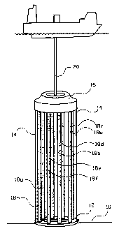
An example of a diagrammatically shown embodiment of the
invention is shown in a perspective view when an underwater
installation occupies a production phase.
On the seabed 10, a subsea frame 12 has been installed in an
introduction phase, forming an anchor for lines 14 for
submerging and lateral positioning of a buoyancy based hollow
body 16.
The underwater installation according to the invention is
suitable for use at large depths of the ocean, e.g. 400 -
4000 metres, and the submerged buoyancy body 16 may e.g. be
placed at a depth of e.g. 150 metres, where the influence
from the waves is very small, causing a moderate variation in
the load on tension struts for the anchoring of the buoyancy
body 16 on the seabed.
After e.g. eight wells are predrilled to 13 3/8 inches,
casing liner strings 18a, 18b, 18c, 18d, 18e, 18f, 18g, 18h

CA 02248683 1998-09-10
WO 97/34074 PCT/N097/00068
4 -
are lowered from a floating platform (not shown) to be
screwed to the upper threaded end of last set casings, during
which the liner strings 18a - 18h pass through vertically
aligned passages, not shown, in the buoyancy body 16. In the
production phase, the buoyancy body 16 is closed uppermost,
except for a central opening for a production hose 20. After
having been screwed to said upper end of last set casings,
these casing liner strings 18a - 18h, the number of which
corresponds to the number of wells, are attached to the
buoyancy body 16 with the upper end thereof. During this
attachment, the temporary anchor lines 14 may be tightened
for, thereafter, to be slackened, transferring the tension
strain to "the tension struts" 18a - 18h according to the
invention which, thus, are tensioned and tightened.
The temporary anchor lines 14 may be removed when the
underwater installation is ready for production.
As mentioned, one or more casing-liner strings 18a - 18h have
a double function, namely as a casing and a tension strut. In
the embodiment shown, the wells upon completion are
considered as being continuous from the reservoir up to the
buoyancy based, tension leg/strut anchored, submerged hollow
body which is positioned at a depth of another order than the
seabed. The invention represents large simplifications in
relation to known and conventional technique, and enables the
utilization of already established technology such as
operations associated to drilling at very large depths of the
ocean as well as socalled floating production.

Representative Drawing
A single figure which represents the drawing illustrating the invention.
Administrative Status

2024-08-01:As part of the Next Generation Patents (NGP) transition, the Canadian Patents Database (CPD) now contains a more detailed Event History, which replicates the Event Log of our new back-office solution.

Please note that "Inactive:" events refers to events no longer in use in our new back-office solution.

For a clearer understanding of the status of the application/patent presented on this page, the site Disclaimer , as well as the definitions for Patent , Event History , Maintenance Fee  and Payment History  should be consulted.

Event History

Description Date
Time Limit for Reversal Expired 2017-03-07
Letter Sent 2016-03-07
Letter Sent 2013-05-22
Inactive: Single transfer 2013-05-02
Letter Sent 2006-10-16
Inactive: Single transfer 2006-09-11
Grant by Issuance 2006-04-18
Inactive: Cover page published 2006-04-17
Inactive: IPC from MCD 2006-03-12
Pre-grant 2006-02-02
Inactive: Final fee received 2006-02-02
Notice of Allowance is Issued 2005-09-07
Letter Sent 2005-09-07
Notice of Allowance is Issued 2005-09-07
Inactive: Approved for allowance (AFA) 2005-08-30
Amendment Received - Voluntary Amendment 2005-06-03
Inactive: S.30(2) Rules - Examiner requisition 2005-04-28
Amendment Received - Voluntary Amendment 2004-09-08
Inactive: S.30(2) Rules - Examiner requisition 2004-03-09
Inactive: S.29 Rules - Examiner requisition 2004-03-09
Amendment Received - Voluntary Amendment 2002-01-31
Letter Sent 2001-11-21
All Requirements for Examination Determined Compliant 2001-10-18
Request for Examination Requirements Determined Compliant 2001-10-18
Request for Examination Received 2001-10-18
Inactive: IPC assigned 1998-11-24
Classification Modified 1998-11-24
Inactive: First IPC assigned 1998-11-24
Inactive: Notice - National entry - No RFE 1998-11-10
Application Received - PCT 1998-11-06
Application Published (Open to Public Inspection) 1997-09-18

Abandonment History

There is no abandonment history.

Maintenance Fee

The last payment was received on 2006-01-26

Note : If the full payment has not been received on or before the date indicated, a further fee may be required which may be one of the following

  • the reinstatement fee;
  • the late payment fee; or
  • additional fee to reverse deemed expiry.

Please refer to the CIPO Patent Fees web page to see all current fee amounts.

Owners on Record

Note: Records showing the ownership history in alphabetical order.

Current Owners on Record
MEPS-FIRST OIL LTD.
Past Owners on Record
TERJE MAGNUSSEN
Past Owners that do not appear in the "Owners on Record" listing will appear in other documentation within the application.
Documents

To view selected files, please enter reCAPTCHA code :


To view images, click a link in the Document Description column. To download the documents, select one or more checkboxes in the first column and then click the "Download Selected in PDF format (Zip Archive)" or the "Download Selected as Single PDF" button.

List of published and non-published patent-specific documents on the CPD .

If you have any difficulty accessing content, you can call the Client Service Centre at 1-866-997-1936 or send them an e-mail at CIPO Client Service Centre.


Document
Description 
Date
(yyyy-mm-dd) 
Number of pages   Size of Image (KB) 
Representative drawing 1998-11-26 1 13
Abstract 1998-09-10 1 60
Description 1998-09-10 4 171
Claims 1998-09-10 3 99
Drawings 1998-09-10 1 34
Cover Page 1998-11-26 1 55
Description 2002-01-31 6 247
Claims 2002-01-31 3 92
Description 2004-09-08 6 233
Claims 2004-09-08 3 78
Claims 2005-06-03 3 84
Representative drawing 2006-03-21 1 18
Cover Page 2006-03-21 1 52
Notice of National Entry 1998-11-10 1 192
Reminder - Request for Examination 2001-11-08 1 118
Acknowledgement of Request for Examination 2001-11-21 1 179
Commissioner's Notice - Application Found Allowable 2005-09-07 1 161
Courtesy - Certificate of registration (related document(s)) 2006-10-16 1 105
Courtesy - Certificate of registration (related document(s)) 2013-05-22 1 126
Maintenance Fee Notice 2016-04-18 1 169
PCT 1998-09-10 10 390
Fees 2003-02-10 1 50
Fees 2002-02-11 1 52
Fees 2000-02-08 1 50
Fees 2001-02-06 1 50
Fees 2004-02-03 1 53
Fees 2005-01-26 1 54
Correspondence 2006-02-02 1 51
Fees 2006-01-26 1 51
Fees 2007-02-05 1 50
Fees 2008-01-29 1 58
Fees 2009-02-05 1 66
Fees 2010-02-04 1 64
Fees 2011-03-07 1 69
Fees 2012-03-07 1 66