Note: Descriptions are shown in the official language in which they were submitted.
CA 02248846 1998-08-31
W O 97/31S23 PCT/LE97/00013
"Apparatus for dispensing and laying
a sheet of film material"
The present invention relates to apparatus for dispensing a sheet
of film material from a roll and laying the film material on the
ground subsequent to sowing seeds by a seed sower so that the film
material covers the area where the seeds have been sown. In
particular, the invention relates to such apparatus for use in the
sowing of maize, although the invention is not~limited to such
apparatus.
Apparatus for dispensing sheet film material from a roll and
laying the film material on the ground are known. For example,
U.S. Patent Specification No. 4,092,936 discloses a device,
particularly for tobacco seed, in which seed tape is laid on the
soil, covered with sheet material and the edges of the sheet
material urged into open furrows or cavities. The device
disclosed is a combined sowing and covering device specifically
for use with seed tape carrying tobacco seeds.
French Patent Specification No. 2,580,459 discloses an apparatus
for dispensing a sheet of film material from a roll. The relative
locations of the roll of plastics film material and the wheels of
the device result in a device with a tendency to stretch the
plastics film material. In addition, the device of the prior art
requires the use of an unrolling roller and is subject to
disruption on uneven surfaces resulting in damage to the plastics
material.
Moreover, recent developments in maize sowing demands the use of
extremely fine gauge plastics sheet material incompatible with the
devices of the prior art. More particularly, many of the devices
of the prior art are specifically designed to stretch the entire
surface of the plastics sheet material being dispensed which can
result in damage or tearing of the plastics material.
CA 02248846 1998-08-31
W O97/31523 PCT/nE97/00013
Accordingly, a need exists for an apparatus for dispensing and
laying a sheet of film material which avoids undesirable
stretching of the film material.
An object of the invention is to provide an apparatus for
5 dispensing and laying a sheet of film material adaptable to the
soil surface.
According to the invention there is provided apparatus for
dispensing a sheet of film material from a roll and laying the
film material on the ground subsequent to sowing seeds by a seed
sower, the apparatus comprising a main framework, a main mounting
means on the main framework for mounting the apparatus rearwardly
of the seed sower relative to the direction of motion of the seed
sower, a secondary framework connected to the main framework, a
pair of spaced apart ground engaging wheels rotatably mounted on
the secondary framework, a rotatable idler means rotatably mounted
on the secondary framework, and forming with the ground engaging
wheels a receiving means for the roll, the ground engaging wheels
being located on the secondary framework for engaging the roll
adjacent the ends thereof for rotating the roll, the ground
engaging wheels acting as a dispensing and laying means for
dispensing film from the roll and laying the film over the groundr
a pair of forwardly mounted spaced apart front coulters for
forming a pair of respective furrows in the ground for engagement
by the ground engaging wheels so that the ground engaging wheels
locate side edges of the film in the respective furrows, and a
pair of rearwardly mounted spaced apart rear coulters for closing
the furrows for entrapping the side edges of the film material
therein.
In one aspect of the invention the ground engaging wheels are
freely rotatably mounted on the secondary framework so that, as
the apparatus is trailed over the ground, the ground engaging
wheels rotate for dispensing and laying the film on the ground.
CA 02248846 l998-08-3l
W O 97/31523 PCT~E97/00013
Preferably, the receiving means for the roll comprises a cradle
for receiving a roll. The receiving means for the roll is
disposed forwards of the ground engaging wheels.
Advantageously, the main framework is pivotably mountable relat;ve
S to the seed sower about a main pivot axis for permitting pivotal
movement of the apparatus about the main pivot axis to accommodate
uneven ground. The main pivot axis extends substantially
horizontally in a general longitudinal direction parallel to the
direction of motion.
Suitably, the secondary framework is pivotally connected to the
main framework about a secondary pivot axis to facilitate pivotal
movement of the secondary framework relative to the main framework
about the secondary pivot axis for accommodating uneven ground.
Preferably, the secondary pivot axis (14) comprises a
substantially horizontal secondary pivot axis (14) extending
substantially transversely of the direction of motion.
The idler means preferably comprises a pair of spaced apart idler
rollers rotatably mounted on the secondary framework for rollably
engaging the roll. Suitably, the idler rollers are located
adjacent to, but spaced apart from, the ground engaging wheels.
Advantageously, a pressure means is provided for urging the film
material into engagement with the ground engaging wheels.
Suitably, the pressure means is located adjacent the ground
engaging wheels at a location just before the ground engaging
wheels urge the film material into the respective furrows.
Preferably, the pressure means comprises a pair of pressure
rollers rotatably mounted on the secondary framework for engaging
respective ground engaging wheels.
The invention also optionally comprises support means for
supporting the sheet material between the ground engaging wheels.
CA 02248846 1998-08-31
W O 97t31523 PCT/IE97/00013
Suitably, the support means comprises at least one transverse bar.
Preferably, the at least one bar is mounted below the rotational
axis of the ground engaging wheel adjacent the perimeter of the
ground engaging wheel so that sheet material can pass between the
S bar and the ground engaging wheel.
Suitably, at least one support wheel is disposed between the
ground engaging wheels for supporting sheet material between the
ground engaging wheels.
Advantageously, at least one support wheel is adapted to stretch
sheet material.
Preferably, the apparatus further comprises punching means for
punching sheet material. Suitably, a first punching means is
adapted to puncture plant holes in said sheet material.
Preferably, a second puncturing means is adapted to puncture water
holes in sheet material. Suitably, the puncturing means are
mounted adjacent the pressure means.
The apparatus preferably further comprises a cutting means for
cutting a sheet from a roll.
Suitably, the cutting means comprises an elongate blade mounted on
the secondary framework and having a cutting edge engageable
transversely of the sheet material, the blade being moveable
be-tween an idle position and a cutting position for severing the
sheet material intermediate the roll and the ground.
Advantageously, the sheet material is severable in a forwards
motion of the blade between the idle and cutting positions.
The invention also comprises a drive means for urging the cutting
means between the idle and the cutting positions. Suitably, the
CA 02248846 1998-08-31
W O 97/31523 PCTlnE97/00013
drive means comprises a hydraulic ram.
Advantageously, the apparatus further comprises biasing means to
bias the cutting blade in the idle position.
..
Suitably, the cutting means displaces soil between the cutting and
idle positions.
In a preferred embodiment of the invention mud flaps are disposed
rearwards of the ground engaging wheels.
Preferably, the apparatus of the invention is adapted for mounting
rearwardly of a seed sower.
The invention will be more clearly understood from the following
description of an embodiment thereof which is given by way of
example only with reference to the accompanying drawings in which:
Fig. 1 is a side perspective view, partially cut away, of
apparatus according to the invention for dispensing a film
from a roll, and for laying the film on the ground;
Fig. 2 is a perspective view of the apparatus of Fig. 1
shown from the rear;
Fig. 3 is a diagrammatic side elevation of the important
features of the apparatus of Fig. 1 with the direction of
movement of the plastics material indicated by the arrows;
Fig. 4 is a partially cut away diagrammatic front elevation
of half the apparatus of Fig. 1 illustrating the support
bars and cutting knife of the apparatus;
Fig. 5 is a diagrammatic plan view from above of a portion
of the apparatus of Fig. 1 illustrating the roll of plastics
(in broken lines), the wheels, coulters, main pivot axis and
CA 02248846 1998-08-31
WO 97/31523 PCT/IE97/00013
secondary pivot axis of the apparatus;
Fig. 6 is a cross-sectional view of the ground illustrating
the apparatus of Fig. l in use with the wheels shown in
broken lines;
Fig. 7 is a cross-sectional view of the ground illustrating
a plastics film having been laid on the ground and secured
thereto by the apparatus of Fig. 1;
Fig. 8 is a rear perspective view of a second embodiment of
an apparatus according to the invention attached to a seed
sower with a second seed sower disposed parallel to the
first seed sower;
Fig. 9 is a side elevation of the apparatus of Fig. 8
showing the relative positions of the wheels, rollers and
idlers of the device with the roller in the operating
position;
Fig. 10 is an enlarged plan view from above of a portion of
the apparatus of Fig. 8 with the roller in the resting
position;
Fig. 11 is a schematic plan view from above of the pressure
rollers, support rollers and ground engaging wheels showing
the regions in which the sheet material is selectively
stretched;
Fig. 12 is a diagrammatic side elevation of the rollers,
idlers, support bars, coulters, etc. of the apparatus of
Fig. 8 with the direction of movement of the plastics
material being indicated by arrows;
Fig. 13 is an enlarged perspective view of a portion of the
idlers, rollers and plastics cutting means of the apparatus
CA 02248846 1998-08-31
W O97/31523 PCT~Eg7/00013 _
of Fig.8;
Fig. 14 is a side elevation of the cutting knife and mud
flap arrangement disposed to the rear of the apparatus of
Fig. 8 with the cutting knife in the resting position;
Fig. 15 is a side elevation of the cutting knife of Fig. 14
with the cutting knife in the operating position;
Fig. 16 is a rear perspective view of the apparatus of Fig.
8 with a plastics film laid on the ground and the cutting
knife in the resting position;
Fig. 17 is a cross-sectional view of the ground following
application of a plastics sheet to the ground before
covering of the edges of the plastics sheet with soil w;th
stretched portions of the plastics being schematically shown
as raised portions over the seeds;
Fig. 18 is a cross-sectional view of the ground of Fig. 17
with the soil covering the s;des of the plastics sheet and
the plastics sheet being suspended between the raised
mounds;
Fig. 19 is cross-sectional view as shown in Fig. 17 with a
seedling growing in the stretched region of the plastics;
Fig. 20 is a diagrammatic plan view from above of the wheels
and plastics sheet of the apparatus of Fig. 8, with the
plastics sheet laid on the ground and the direction of
movement of the apparatus being indicated by arrows;
Fig. 21 is a side elevation of a mounting frame for use in
the apparatus according to the invention, the mounting frame
having a drive wheel for driving a roller for preparing the
ground prior to application of the plastics film material;
CA 02248846 1998-08-31
WO 97/31523 PCT/IE97/00013
Fig. 22 is a side perspective view of an alternative side
mounting bracket incorporating a soil raiser for use in the
apparatus of the invention, and
Fig. 23 is a top view of a portion of the mounting bracket
of Fig. 22, a ground engaging wheel and a solid support
wheel.
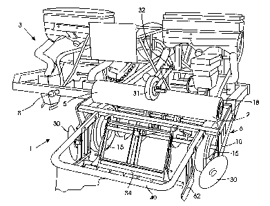
Referring to the drawings there is illustrate~d apparatus according
to the invention indicated generally by the reference numeral 1
for mounting rearwardly of a seed sower 3, which is illustrated
only in block representation, and which is in turn mounted to a
three point linkage of a tractor (not shown). The apparatus 1 is
suitable for dispensing film material 5 from a roll 2 and laying
the film 5 on the ground for covering an area in which maize seeds
are sown by the seed sower 3. The apparatus 1 is mounted directly
to the rear of the seed sower 3 relative to the direction of
motion of the seed sower 3, which is indicated by the arrow A.
The mounting of the apparatus 1 to the seed sower 3 is described
below. In this embodiment of the invention the film 5 is a
relatively thin, clear plastics material which is suitable for
maintaining heat in the soil to accelerate germination and initial
growth of the maize seed.
The apparatus 1 comprises a main framework 6, which in this
embodiment of the invention comprises a main transversely
extending carrier bar 7. A main mounting means comprising a main
pivot mounting 8 which extends from the carrier bar 7 pivotally
connects the apparatus 1 to the seed sower 3 so that the apparatus
1 can oscillate or is pivotable about a main pivot axis 9 defined
by the main pivot mounting 8. The main pivot axis 9 extends
substantially horizontally and longitudinally parallel to the
direction of motion of the seed sower 3, namely parallel to the
direction of the arrow A.
A secondary framework 10 is carried on the main framework 6, and
.. . .. ..
CA 02248846 1998-08-31
W O 97/31~23 PCT~E97/00013
is connected thereto by a secondary mounting means, in this case,
a pair of secondary pivot mountings 12 which pivotally connect the
secondary framework 10 to the main framework 6. The secondary
pivot mountings 12 define a common secondary pivot axis 14 which
extends substantially horizontally and transversely of the
direction of motion of the seed sower 3.
A pair of ground engaging wheels 15 are rotatably carried at
spaced apart locations on the secondary framework 10 and are
rotatable about a common rotational axis. An idler means
comprising a pair of idler rollers 16, are also rotatably carried
on the secondary framework 10. The idler rollers 16 are located
adjacent to, but spaced apart from, the ground engaging wheels 15,
and form with the ground engaging wheels 15 a receiving means,
namely, a receiving area or cradle for receiving the roll 2. The
ground engaging wheels 15 are located on the secondary framework
10 so that they engage the respective ends 18 of the roll 2.
Thus, as the ground engaging wheels 15 are rotated by trailing the
apparatus 1 along the ground, the roll 2 is rotated in the
direction of the arrow B, and film material 5 is urged from, and
dispensed from the roll 2 by the ground engaging wheels 15.
A pressure means, in this case provided by a pair of pressure
rollers 20, which are rotatably mounted on the secondary framework
10 urge the side edges of the film 5 into engagement with the
ground engaging wheels 15 just above the ground. Although not
illustrated, the pressure rollers 20 are carried on spring-urged
mounting members which are pivotally connected to the secondary
framework 10, and spring-urged into engagement with the ground
engagement wheels 15. A support means comprising three support
bars 22 extend between the ground engaging wheels 15 adjacent the
periphery thereof for supporting the film material intermediate
the ground engaging wheels 15 between the roll 2 and the ground.
A pair of spaced apart front coulters 25 are mounted on the seed
sower 3, but if desired could be mounted on the apparatus 1
.........
CA 02248846 1998-08-31
W O 97131523 PCT/IE97100013
forwardly of the ground engaging wheels 15, for forming respective
furrows 27 in the ground for engagement by the ground engaging
wheels 15. Accordingly, as the ground engaging wheels 15 dispense
the film 5 from the roll 2 onto the ground, the ground engaging
wheels 15 also locate the side edges of the film 5 in the furrows
27. A pair of rear coulters 30 carried on the secondary framework
10, and mounted rearwardly of the ground engaging wheels 15 close
the furrows 27 for entrapping the side edges of the film 5 in the
furrows 27 for securely retaining the film material on the ground.
A retaining means, in this embodiment of the invention a retaining
wheel 31, which is carried on a spring-loaded pivotally mounted
arm 32 retains the roll 2 in engagement with the ground engaging
wheels 15 and the idler rollers 16. The pivot arm 32 is pivotally
connected to the secondary framework 10.
A cutting means for cutting the film 5 from the roll 2 comprises
an elongated knife 34 which extends transversely of the direction
of motion of the seed sower 3, and which is moveable from an idle
position into a cutting position whereby the knife 34 extends
between two of the support bars 22 for cutting the film 5. An
hydraulic ram (not shown) is mounted on the secondary framework 10
for urging the knife 34 from the idle to the cutting position and
vice versa. A mounting mechanism (not shown) mounts the knife in
the secondary framework 10 so that it is moveable from the idle to
the cutting position. The knife 34 is provided with a serrated
cutting edge, and cuts the film by virtue of the fact that the
film 5 is in tension between the roll 2 and the ground.
The seed sower 3, in this embodiment of the invention, is an
ACCORD seed sower which is capable of sowing three spaced apart
rows of maize seed between the ground engaging wheels 15 of the
apparatus 1.
Although not illustrated, in practice, a pair of seed sowers 3
CA 02248846 1998-08-31
W O97131523 PCT/rE97100013
11
will be mounted side by side behind the tractor, and a pair of
apparatus 1 will be mounted behind the seed sowers, one apparatus
1 for each seed sower 3.
In use, the seed sower 3 is mounted to the three point linkage of
a tractor, and the apparatus 1 is mounted by the main pivot
mounting 8 to the seed sower 3. The seed sower 3, and apparatus 1
are lowered downwardly so that the ground engaging wheels 15 of
the apparatus 1 engage the ground. As the tractor commences to
move forward in the direction of the arrow A, the seed sower 3
sows three rows of maize seed in conventional fashion. The front
coulters 25 form the furrows 27 and the ground engaging wheels 15
engage in the furrows 27. As the ground engaging wheels 15
rotate, the action of the ground engaging wheels 15 on the roll 2
rotates the roll 2 in the direction of the arrow B, and the film 5
is carried around the peripheral edge of the ground engaging
wheels 15, and dispensed from the roll 2. The ground engaging
wheels 15 thus locate the side edges of the film 5 in the furrows
27, which as the tractor moves forward are closed by the rear
coulters 30, thus entrapping the film material 5 in the furrows
27. Should the apparatus 1 encounter uneven ground, the apparatus
1 is free to pivot about the main pivot axis 9, and the secondary
framework 10 is free to pivot about the secondary pivot axis 14 so
that the ground engaging wheels 15 continue to engage the furrows
27.
Figs. 8 to 20 show a second embodiment of an apparatus for
dispensing and laying a sheet of film material of the invention.
As shown in Figs. 8 and 9, the apparatus of the second embodiment
is broadly similar to the apparatus of the first embodiment in
that the apparatus, generally indicated by the reference numeral 1
is adapted for mounting rearwardly of a seed sower 3. As shown in
Fig. 8, the seed sower 3 is provided with two seed sowers arranged
side by side. For clarity, only one of the seed sowers 3 is
provided with an apparatus 1 according to the invention. However,
. .
CA 02248846 1998-08-31
WO 97/31523 PCT/IE97100013
12
it is envisaged that a seed sower 3 as shown in Fig. 8 would
normally be provided with two apparatus 1 according to the
invention mounted rearwardly of said seed sowers.
The apparatus according to the invention is adapted for dispensing
5 film material 5 from a roll 2. The apparatus 1 is made up of a
main framework 6 and a secondary framework 10 carried on the main
framework 6.
As shown in the drawings, the main framework 6 is connected by a
main pivot mounting 8 to the seed sower 3 so that the apparatus 1
can oscillate or pivot about a main pivot axis 9 defined by the
main pivot mounting 8 to facilitate adaptability of the device to
rough terrain.
The secondary framework 10 is connected to the main framework 6 by
secondary pivot mountings 12 which pivotally connect the secondary
framework 10 to the main framework 6.
The secondary pivot mountings 12 define a common secondary
pivotable axis 14 about which the secondary frame 10 can pivot as
previously described.
The main pivot or oscillating point 8 in combination with the
secondary pivot points 12 and their corresponding pivot axis
ensure that the apparatus of the invention is highly adaptable to
uneven surfaces to ensure that the sheet material 5 is
consistently applied to the ground without interruption resulting
from uneven surfaces.
The apparatus of the invention has a pair of ground engaging
wheels 15 carried on the secondary framework 10 and rotatable
about a common rotational axis as previously described. The
apparatus is also provided with a retaining wheel 31 carried on a
spring loaded pivotably mounted arm 32 to retain the roll 2 in
engagement with the ground engaging wheels 15 in use.
CA 02248846 1998-08-31
W O 97/31523 PCT/rE97/00013
The apparatus has a pair of rear coulters 30 carried on the
secondary framework 10 as previously described. In the present
embodiment, the rear coulters 30 are made up of rotatable disc
coulters. The apparatus also comprises a rearwardly mounted
S cutting knife 34 which shall be described more fully below.
As shown in Fig. 9, the apparatus 1 has a pair of spaced apart
front coulters 25 also as previously described. To the rear of
the front coulters 25 a soil flattening roller~33 carried by the
main frame 6 is visible. The soil flattening roller 33 serves to
flatten the soil prior to laying of the plastics sheet material as
shall be described more fully below.
A scraper (not shown) is mounted on the roller 33 to effect
removal of accumulated soil matter from the roller to ensure
smooth operation of the roller.
The secondary framework 10 carries the cutting knife 34 at the
rearward end thereof and is attached to the main framework 6 at
the front end thereof. The side members of the secondary
framework 10 define an L-shaped bracket structure with the foot of
the L being disposed in a diagonally upward orientation towards
the rear of the apparatus of the invention. The rear coulters 30
are carried on a carrying arm 35 which extends rearwardly of the
apparatus from the corner of the L-shaped structure. The disc
shaped rear coulters 30 are attached to the carrying arms 35 by
bolts 36.
As shown in Figs. 10 to 13, the ground engaging wheels 15, the
plastics roll 2, and the idler roller 16 are arranged
substantially as previously described in relation to Fig. 3 above.
However, in the present embodiment, the retaining wheel 31 is
urged against the plastics roll 2 from the rear of the apparatus 1
of the invention. In addition, the pressure rollers 20 are
disposed immediately below the idler rollers 16 ;n the space
defined between the plastics film roll 2, the idler roller 16 and
CA 02248846 1998-08-31
W O 97/31523 PCT/IE97/00013
the ground engaging wheel 15 as shown in Fig. 12.
As shown in Fig. 13, pressure rollers 20 are carried on a spring
urged mounting member 37 pivotably connected at either end by
bearings to the secondary framework 10. The pressure rollers
disposed at each end of the mounting member 37 are in contact with
the ground engaging wheels 15 while the pressure rollers 20
mounted on the mounting member 37 between the ground wheel
engaging rollers 20 are of enlarged diameter. the enlarged
diameter pressure rollers 20 serve to stretch the sheet material 5
as shall be more fully described below.
In the present embodiment the support bars 22 are made up of
rotatable elongate support bearings 22 which roll against the
ground engaging wheels 15.
The mounting member 37 is further provided with disc-like primary
punching plates 38 mounted adjacent each pressure roller 20. The
punching plates 38 can be integral with the pressure roller 20 or
alternatively can be attachments mountable on the mounting member
37 adjacent the pressure rollers 20. The punching plates 38 are
provided with a multiplicity of protruding cutting or punching
teeth 39. The cutting teeth 39 impart multiple punch holes to the
plastics material 5 in use as shown in Figs. 16 and 20. The
multiple punched holes in the plastics material are formed in a
continuous series and serve to provide aeration beneath the laid
plastics sheeting material to prevent rotting of germinated or
ungerminated seed.
The mounting member 37 is further provided with a secondary
punching plate 40 disposed centrally between each combination of
pressure roller 20 and primary punching plate 38.
The secondary punching plate 40 is provided with a single punching
tooth 41. The secondary punching plate 40 rotates with the
pressure rollers 20 on the mounting member 37. The secondary
CA 02248846 1998-08-31
W O 97/31523 PCT/IE97/00013
punching plate 40 is disposed over a curved cutting plate 42
mounted on the secondary frame 10. The cutting plate 42 is
provided with an elongate slit 43 for receiving the single tooth
of the secondary punching plate 40 during rotat;on of the
secondary punching plate 40. As shall be explained more fully
below, plastics material travelling between the secondary punching
plate 40 and the curved cutting plate 42 is punched in the region
of the slit 43 by the single tooth 41 of the secondary punching
plate 40 extending into the slit 43. Accordingly, the frequency
of holes punched by the single tooth 41 of the secondary punching
plate 40 is significantly lower as compared with the frequency of
the holes punched by the primary punching plate 38.
The holes punched in the plastics sheet material 5 by the single
tooth 41 of the secondary punching plate 40 serve to allow surface
water accumulated on the plastics sheet 5 following application of
the plastics sheeting 5 to the soil to pass through the plastics
sheeting 5 into the soil thereby preventing flattening of the
plastics sheeting 5 against the surface of the soil and potential
damage to or rotting of seedlings or germinated or ungerminated
seed.
As shown in Fig. 13, the secondary punching plate 40 is made up of
two parts - a first disc 44 permanently mounted on the mounting
member 37 and a second detachable disc, the second detachable disc
being the secondary punching plate 40 proper. The secondary
punching plate 40 is attachable to the permanent disc 44 by
butterfly bolts 45.
In the present embodimentl the secondary frame 10 is further
provided with a tertiary frame 46 disposed between the wheels 15.
The tertiary frame 46 is pivotably mounted on the secondary frame
10 and comprises a transverse bar 47 which extends between the
ground engaging wheels 15 parallel to the mounting member 37.
The transverse bar 47 is provided with a series of solid support
CA 02248846 l998-08-3l
W O 97/31523 PCTAE97/00013
wheels 48. The solid wheels 48 are arranged on the transverse bar
47 such that a plurality of the solid wheels 48 are urged against
a plurality of the pressure wheels 20. However, a number of the
solid wheels 48 have an enlarged diameter and are spaced apart
along the transverse bar 47 such that the larger diameter solid
wheels 48 protrude into a space defined between the enlarged
diameter pressure rollers 20 on the mounting member 37.
Interaction between the larger diameter solid wheels 48 and the
enlarged diameter pressure rollers 20 serves to stretch the
plastics material 5 passing over the larger diameter solid wheels
48 in the area between the enlarged diameter pressure rollers 20
to render the plastics material 5 thinner in said regions to
facilitate penetration of the plastics material by plants
following laying of t~e film material.
The cutting plate 42 bearing the elongate cutting slit 43 as
previously described is mounted on the tertiary frame 46 such that
the external surface of the cutting plate 42 follows the path
defined by the outer edge of the solid wheels 48 of smaller
diameter.
The direction of movement of the plastics sheet material 5 to be
dispensed from the roll 2 can be more fully understood having
regard to Fig. 12 which shows a diagrammatic side elevation of the
ground engaging wheels 15, plastics roll 2, retaining wheel 31,
idler rollers 16, pressure rollers 20, solid wheels 48 and support
bearings 22 with solid arrows indicating the direction of movement
of-the rollers and wheels, and the plastics material and the
direction of movement of the plastics material 5 being indicated
by heavy lines and broken arrows respectively.
As shown in the drawing, the apparatus 1 for dispensing and laying
the sheet of film material 5 is conveyed to the left in the
direction indicated by the arrows. Accordingly, the ground
engaging wheels 15 are urged forwards in an anti-clockwise
, , . ~ . . ,
CA 02248846 1998-08-31
WO 97/31523 PCTIIE97/00013
direction so that the plastics sheet material 5 is unrolled from
the roll 2 in a clockwise direction, the roll 2 being directly
mounted in the cradle on the ground engaging wheels 15 in the
operative position.
5 The retaining wheel 31 (which is urged against the roll 2 of
plastics material by the biased arm 32) is rotated in an anti-
clockwise direction while, similarly, the idler rollers 16 which
rest against the underside of the roll 2 of plastics material 5
are urged in an anti-clockwise direction. The plastics material 5
is directed downwards from the roll 2 between the pressure rollers
20 and the ground engaging wheels 15 and the enlarged diameter
solid wheels 48.
The ground engaging wheels 15 are disposed such that the edges 18
of the sheet material extend beyond the ground engaging wheels 15
so that the plastics material is urged in its entirety into the
soil at its edges to provide a secure anchor as shown in Figs. 17
and 18.
The sheet material is therefore gripped at multiple points during
dispensing i.e. between the roll 2 and the ground engaging wheels
15, between the pressure rollers 20 and the ground engaging wheels
15 and between the solid support wheels 48 and the ground engaging
wheels 15. Finally, the plastics sheet material 5 is held
between the bearings 22 and the ground engaging wheels 15
immediately before entry into furrows 27.
Accordingly, an evenly distributed pressure is exerted on the
plastics material 5 resulting in reduced tearing and damage and
ease of use of fine gauge plastics sheet material.
In passing between the pressure rollers 20, the ground engaging
wheels 15 and the solid wheels 48 the plastics sheet material 5 is
simultaneously punched by the primary punching plate 38 and the
secondary punching plate 40 as previously described and stretched
in the spaces between the pressure wheels 20 by the solid wheels
CA 02248846 1998-08-31
WO 97/31523 PCTIIE97/00013
.
18
48 of enlarged diameter.
Figs. 17 and 18 show schematic representations of the sheet
material following laying of the material 5. As shown in the
drawings, the sheet material has been selectively stretched to
reduce the thickness of the sheet material in the region of the
sown seed. For example, a plastics sheet material 5 having a
thickness of 6 to 12 microns before stretching could be reduced to
a thickness of 3 microns following stretching.
The plastics sheet material 5 is then passed between the three
elongate support bearings 22 and the ground engaging wheels 15.
The elongate support bearings 22 serve to guide the plastics sheet
material against the ground engaging wheels 15 which in turn draw
the plastics sheet material 5 from the roll 2 and urge the
plastics sheet material 5 against the soil at the edges 18 of the
plastics sheet material 5.
Accordingly, in the present embodiment, the plastics sheet
material 5 can be controllably and selectively perforated and
stretched as required in accordance with prevailing weather
conditions and/or the growth conditions required. Similarly, the
relative diameters of the support wheels 48, pressure wheels 20
and idler rollers 16 ensure that the plastics material 5 is in no
way damaged.
As shown in Fig. 12l the plastics material travels in a clockwise
manner from the roll 2 and downwards in an anti-clockwise manner
over approximately half the circumference of the ground engaging
wheel 15. The plastics sheet material 5 therefore makes
comparatively brief contact with the ground engaging wheels 15 but
yet sufficient contact to ensure that the plastics material 5 is
drawn from the roll 2 and urged into the soil. The degree of
contact of the plastics material 5 from the roll 2 with the ground
engaging wheels 15 is facilitated by the relative positions of the
plastics roll 2, idler rollers 16 and ground engaging wheel 15.
CA 02248846 1998-08-31
W O 97/31523 PCT~E97/00013
19
More particularly, the plastics roll 2 is cradled forward of the
ground engaging wheels 15 between the ground engaging wheel 15 and
the idler roller 16 such that the path travelled by the plastics
material 5 during disposing of the plastics mater;al 5 is
minimised to avoid uncontrollable and undesired stretching of the
plastics material 5.
Figs. 14 and 15 show side elevations of a portion of the
embodiment of the invention shown in Fig. 8 and more particularly
show an enlarged view of the cutting knife 34. The direction of
movement of the apparatus is indicated by an arrow in Figs. 14 and
15 while Fig. 14 shows the cutting knife 34 in a resting position
and Fig. 15 shows the cutting knife 34 in a cutting position.
Fig. 16 which is a rear perspective view from above of the
apparatus of the ;nvention clearly illustrating the cutting knife
34. Figs. 14 and 15 also illustrate a mud flap support frame 49
which extends rearwardly and outwards from the secondary frame 10
of the apparatus of the invention. The mud flap frame 49 is
omitted from Fig. 16 for clarity.
As shown in Figs. 14, 15 and 16, the cutting knife generally
indicated by the reference numeral 34 is made up of a pivotable
rearwardly extending rectangular frame 50 pivotably mounted on the
secondary frame 10 of the apparatus 1 of the invention. The
rectangular knife frame 50 is made up of a first side bar 51 and a
second side bar 52. The side bars 51,52 are pivotably connected
to the rear of the secondary frame 10. The knife frame 50 is
further provided with two transverse bars 53,54 to complete the
rectangular knife frame 50. A central support bracket 55 made up
of two elongate spaced apart bars is disposed between the
transverse bars 53,54. The support bracket 55 serves as a
mounting bracket to which a hydraulic ram 57 is connected. The
hydraulic ram 13 is in turn connected to manually operable control
means (not shown). Extension and retraction of the hydraulic ram
57 causes the knife frame 50 to pivot upwards and downwards as
.
CA 02248846 1998-08-31
WO 97/31523 PCT/IE97100013
shall be explained more fully below.
The knife frame 50 has two biased springs 58 which extend between
the transverse bars 53,54 adjacent the outer face of each of the
side bars 51,52. The biased springs 58 serve to cause the knife
frame 50 to spring return to the resting position shown in Fig. 13
following a cutting action. The spring return movement displaces
soil onto plastics sheet material 5 laid to the rear of the
apparatus of the invention (see below).
At its end remote from the secondary frame 10, the knife frame 50
is provided with an elongate toothed cutting blade 59. The teeth
60 of the cutting blade 59 are clearly shown in Fig. 16. The
teeth 60 are oriented downwards towards the laid plastics material
5.
Fig. 14 shows the knife frame 50 disposed outwards and rearwardly
of the apparatus of the invention, i.e. in the resting position.
The knife frame 50 is urged rearwardly by the hydraulic ram 57. A
cutting motion is achieved by retraction of the hydraulic ram 57
to draw the knife frame ~0 inwards towards the front of the
apparatus 1 of the invention about the pivot point defined between
the side bars 51,52 and the secondary frame 10. Retraction of the
hydraulic ram 57 causes the teeth 60 to sever plastics material
emerging from beneath the ground engaging wheels 15 in a forwards
direction thereby preventing excessive stretching of laid plastics
sheet material 5.
Following cutting of the plastics material 5, the biased springs
58 pull the knife frame 50 rearwards to revert to the resting
position shown in Fig. 14. The bias provided by the springs 58
causes the knife frame 50 to return to the starting position at
speed. During the return movement, the cutting blade 59 strikes
the soil behind the ground engaging wheels 15 to urge soil upwards
and rearwards onto the free end of severed plastics material 5 to
secure the free end of plastics material 5 in position in the
. .
CA 02248846 1998-08-31
WO 97131523 PCT/IE97/00013
Soi 1 .
As shown in Figs. 14 and 15, the mud flap frame 49 is disposed
outwards and rearwards from the secondary frame 10 over the knife
frame 50. The mud flap frame 49 is provided with a rear end mud
flap 61 which extends from the mud flap frame 49 and makes contact
with the ground. The rear end mud f7ap 61 serves to restrict soil
thrown upwards following a cutting motion by the knife frame 50 to
the region adjacent the free end of the laid plastics material 5.
The mud flap frame 49 is also provided with two side mud flaps 62
(see Fig. 8) at either side disposed downwards and parallel with
the ground engaging wheels 15. The side mud flaps 62 serve to
prevent excessive soil from being thrown transversely inwards by
the coulters 30 during forwards movement of the apparatus of the
invention. It is important to prevent excessive coverage of the
sheet 5 - particularly when the apparatus of the invention is
moving at speed.
Fig. 21 shows a side elevation of an alternat;ve secondary
mounting frame 10 suitable for use in the apparatus according to
the invention.
The mounting frame 10 is adapted to provide a drive means for the
roller 33. As shown in the drawing, the mounting frame 10 is
attached to the ground engaging wheels 15 and an end mounting of
the roller 33. However, the mounting frame 10 is further provided
with a carrying arm 63 which extends from the free end of the
flattening roller 33 mounting parallel to the direction of
movement of the apparatus 1. The arm 63 at its free end is
provided with a paddle type rotatable wheel 64 having paddles 65
extending tangentially outwards therefrom. Forwards movement of
the apparatus 1 of the invention causes the paddles 65 to engage
the ground. The paddles 65 are connected by a gear mechanism (not
~ shown) to the rear of the carrying arm 63 to the flattening roller
33 to drive the flattening roller 33 during forward movement of
.. ~, . . . .
CA 02248846 1998-08-31
W O 97/31523 PCT/IE97/00013
22
the apparatus 1.
Rotation of the flattening roller 33 ensures that soil does not
build up upon contact with the flattening roller 33 which can
disrupt the seed sowing process.
Figs. 22 and 23 show an alternative embodiment of a side mounting
for use in the apparatus of the invention. As shown in the
drawings, the bracket is provided with a soil raising arm 66 which
extends rearwards behind the flattening roller 33 (not shown). The
soil raising arm 66 is made up of a finger-like projection having
an inwardly hooked or kinked end 67. The kinked end 67 displaces
soil inwards and upwards before application of the sheet material
to the ground to form a continuous elongate raised mound 68 (see
Figs. 17 and 18) either side of the flattened soil adjacent each
furrow 27. Accordingly, following application of the sheet
material 5 as hereinabove described, the sheet material is
suspended between the two parallel mounds 68.
An advantage of the raised mounds 68 is that the applied sheet
does not bear down on the seed/soil thereby allowing air and
moisture circulation to encourage growth.
In use (see in particular Figs. 14 to 20), the seed sower 3 is
mounted to the three point linkage of a tractor as previously
described. The apparatus of the second embodiment is then mounted
at the main pivot mounting 8 to the seed sower 3. Generally, two
apparatus 1 will be mounted side by side to two seed sowers 3 as
shown in Fig. 8. The seed sowers 3 and the apparatus 1 are
lowered downwards so that the ground engaging wheels 15 of the
apparatus 1 engage the ground. Forwards movement of the seed
sowers 3 causes the seed sowers 3 to sow three rows of seed, for
example maize seed, in conventional fashion. The flattening
roller 33 flattens the seeds into the soil following sowing of the
seeds while the front coulters 25 form furrows 27 in which the
following ground engaging wheels 15 travel. Rotation of the
CA 02248846 1998-08-31
W O 97/31523 PCT~E97/00013
ground engaging wheels 15 causes the plastics material 5 to be
drawn from the plastics roll 2 as previously described. The
ground engaging wheels 15 therefore locate the edges 18 of the
plastics material 5 in the furrows 27. The disc like rear
coulters 30 urge soil inwards into the furrows 27 to cover the
edges 18 of the film material 5 with soil thus entrapping the film
material 5 in the furrows 27 as previously described. The cutting
knife 34 is then actuated to sever the laid plastics material 5
when required.
Location of the roll 2 in the cradle defined between the idler
roller 16 and the ground engaging wheels 15 and the subsequent
path travelled by the plastics material 5 ensures that firstly
undesirable stretching of the plastics material 5 does not take
place, secondly stretching of the plastics material is effected at
predetermined locations to facilitate easy penetrat;on of the
plastics material by germinated seeds, and thirdly punching of
holes in the plastics material 5 by the primary and secondary
punching plates 38,40 to provide aeration beneath the plastics
material 5 and to prevent surface water from accumulating on the
plastics material 5.
Fourthly, the apparatus 1 is free to oscillate and pivot about the
main pivot axis 9 and the secondary framework 10 is free to pivot
about the secondary pivot axis 14 so that the ground engaging
wheels 15 continue to engage the furrow 27 independently of uneven
ground conditions.
Finally, the arrangement of the support bearings 22 and pressure
rollers 20 together with the ground engaging wheels 15 and idler
rollers 16 without the use of a plastics laying roller ensures
that damage to the plastics material by pebbles and stones
extending upwards from the soil is minimised.
It is also envisaged that a protective plate could be mounted
adjacent the support bearings 22 to prevent stones and other
. . . , . ~ ,.. . . . .
CA 02248846 1998-08-31
W O 97/31523 PCT/nE97/00013
24
materials displaced upwards during travel of the apparatus 1 from
penetrating the plastics material and causing damage or
undesirable punching thereof.
The apparatus of the invention can be formed from many suitable
materials known in the art. Advantageously, the pressure rollers
20 are formed from a nylon material while the support wheels 48
are formed from rubber material.
The apparatus of the invention can be adapted for many uses. For
example, the apparatus can be adapted to hold a tank for
containing a herbicide or fertiliser. Tubes extending from the
tank could be used to automatically spray the soil before and/or
after laying of the plastics material. An advantage of spraying
is that weed growth beneath the plastics material 5 can be
prevented by a herbicide while a herbicide applied following
laying of the plastics material can prevent weed growth adjacent
the edges of the plastics material 5.
For example, three spray heads can be oriented to spray beneath
the sheet material, a further two spray heads can be disposed
either side of the plastics material and a further single spray
head disposed between two apparatus of the invention when mounted
side by side behind two seed sowers.
Similarly, application of a fertiliser can enhance germination and
growth of germinated seed beneath the plastics material.
The apparatus of the invention is particularly suited for use with
plastics material having narrow gauges, e.g. plastics material
having a thickness of less than 10 microns or indeed 6 microns and
below.
The invention is not limited to the embodiment hereinbefore
described which may be varied in construction and detail.