Language selection

Search

Patent 2249090 Summary

Third-party information liability

Some of the information on this Web page has been provided by external sources. The Government of Canada is not responsible for the accuracy, reliability or currency of the information supplied by external sources. Users wishing to rely upon this information should consult directly with the source of the information. Content provided by external sources is not subject to official languages, privacy and accessibility requirements.

Claims and Abstract availability

Any discrepancies in the text and image of the Claims and Abstract are due to differing posting times. Text of the Claims and Abstract are posted:

  • At the time the application is open to public inspection;
  • At the time of issue of the patent (grant).
(12) Patent Application: (11) CA 2249090
(54) English Title: LOW WATER LEVEL INDICATOR
(54) French Title: JAUGE DE BAS NIVEAU D'EAU
Status: Deemed Abandoned and Beyond the Period of Reinstatement - Pending Response to Notice of Disregarded Communication
Bibliographic Data
(51) International Patent Classification (IPC):
  • G01F 23/22 (2006.01)
  • A01G 27/00 (2006.01)
  • A47G 33/12 (2006.01)
  • G01F 23/24 (2006.01)
(72) Inventors :
  • RADKE, ROBERT E. (United States of America)
  • KURSEL, THOMAS C. (United States of America)
(73) Owners :
  • THOMAS, C. KURSEL
(71) Applicants :
  • THOMAS, C. KURSEL (United States of America)
(74) Agent: SMART & BIGGAR LP
(74) Associate agent:
(45) Issued:
(22) Filed Date: 1998-09-29
(41) Open to Public Inspection: 2000-03-29
Examination requested: 1998-09-29
Availability of licence: N/A
Dedicated to the Public: N/A
(25) Language of filing: English

Patent Cooperation Treaty (PCT): No

(30) Application Priority Data: None

Abstracts

English Abstract


A low water level indicator includes a detection assembly and
an indicator unit. The detection assembly comprises a housing, a
pair of electrodes, a control unit, and a battery. The indicator
unit comprises a light emitting diode (LED) and a base. The
housing is preferably molded as two halves which are joined at
assembly. An adjustment rod is held by a first and second snap
retainer at substantially the bottom of the housing. The
adjustment rod is used to adjust the height of the bottom of the
housing relative to a water container. The electronic control
circuit is mounted in a top cavity. A hook rod is held by a top
spring clip which is disposed at substantially the top of the
housing. The hook rod is used to provide stability for the
placement of the detection assembly. A second embodiment of the
low water level detector utilizes at least one eye loop projection
and a filament means to suspend the detection assembly from a tree.
When the water level in a water container is too low, electrical
current will no longer pass from the first electrode to the second
electrode through the water. When current flow ceases between the
first and second electrode, the LED will emit light until the water
level is raised.


Claims

Note: Claims are shown in the official language in which they were submitted.

I claim:
1. A low water level indicator comprising:
a detection assembly having a housing, a first electrode, a
second electrode, and an electronic control circuit, said first and
second electrodes being electrically connected to said electronic
control circuit;
a power source supplying said electronic control circuit; and
an indicator unit having an LED, said LED being electrically
connected to said electronic control circuit; and
said electronic control circuit inputing current from a DC
voltage source through a current limiting resistor, said DC voltage
traveling through water in a water container from a first electrode
to a second electrode.
2. The low water level indicator of claim 1, further
comprising:
said electronic circuit having a comparator, said power source
supplying said first electrode with current, said second electrode
being connected to the inputs of said comparator, wherein when the
water level in a container is low, said comparator causing a LED to
emit light.
3. The low water level indicator of claim 2, further
comprising:
said electronic control circuit having an oscillator connected
between said comparator and said LED, wherein when the level in a
12

container is low, said comparator causing said LED to
intermittently emit light.
4. The low water level indicator of claim 1, further
comprising:
at least one eye loop projection extending outward from an
upper portion, said at least one eye loop projection allowing said
low water indicator to be suspended with a filament means.
5. The low water level indicator of claim 1, further
comprising:
said housing having a control cavity at a top thereof, said
electronic control circuit unit being retained in said control
cavity, said electronic control circuit being isolated from
moisture inside said control cavity.
6. The low water level indicator of claim 5, further
comprising:
a top spring clip being attached to said housing at
substantially the top thereof; and
a hook rod being inserted into said top spring clip, said hook
rod becoming slidable when said top spring clip is squeezed, said
hook rod facilitating the attachment to a branch of a Christmas
tree.
13

7. The low water level indicator of claim 1, wherein:
said housing having at least one opening in a lower portion at
substantially the bottom thereof.
8. The low water level indicator of claim l, further
comprising:
a hook being attached to a top of said indicator unit, said
hook facilitating the attachment to a branch of a Christmas tree.
9. The low water level indicator of claim 1 wherein:
said housing having at least one opening in a side at
substantially the bottom thereof.
10. The low water level indicator of claim l, further
comprising:
a first snap retainer being molded on to a first half housing
a plurality of support cavities being formed in said first half
housing above said first snap retainer;
a second snap retainer being molded on to a second half
housing a plurality of support cavities being formed in said second
half housing above said second snap retainer; and
an adjustment rod being inserted between said first and second
snap retainers and said support cavities.
14

11. The. low water level indicator of claim 1, wherein:
said power source being a battery; and
a battery plate being removable from said housing, said
battery plate providing access to said battery.
12. A low water level indicator comprising:
a detection assembly having a housing, a first electrode, a
second electrode, and an electronic control circuit, said first and
second electrodes being electrically connected to said electronic
control circuit;
a power source supplying said electronic control circuit;
an indicator unit having a base and an LED, said LED, and said
power source being electrically connected to said detection
assembly; and
said electronic control circuit having a first schimdt trigger
nand gate and an oscillator, said first schmidt trigger nand gate
inputing the current from a DC voltage source through a current
limiting resistor, said DC voltage traveling through water in a
water container, when said water level is low, said first schmidt
trigger nand gate outputing a voltage high, said oscillator
including at least one schmidt trigger nand gate.
13. The low water level indicator of claim 12, further
comprising:
said electronic control circuit having said oscillator
connected between said first schmidt trigger nand gate and said
15

LED, wherein when the level in the water container is low, said
oscillator receiving the voltage high from said first schmidt
trigger nand gate, said oscillator causing said LED to
intermittently emit light.
14. The low water level indicator of claim 12, further
comprising:
at least one eye loop projection extending outward from an
upper portion, said at least one eye loop projection allowing said
low water indicator to be suspended with a filament means.
15. The low water level indicator of claim 12, further
comprising:
said housing having a control cavity at a top thereof, said
electronic control circuit unit being retained in said control
cavity, said electronic control circuit being isolated from
moisture inside said control cavity.
16. The low water level indicator of claim 15, further
comprising:
a top spring clip being attached to said housing at
substantially the top thereof; and
a hook rod being inserted into said top spring clip, said hook
rod becoming slidable when said top spring clip is squeezed, said
hook rod facilitating the attachment to a branch of a Christmas
tree.
16

17. The low water level indicator of claim 12, wherein:
said housing having at least one opening in a lower portion at
substantially the bottom thereof.
18. The low water level indicator of claim 12, further
comprising:
a hook being attached to a top of said indicator unit, said
hook facilitating the attachment to a branch of a Christmas tree.
19. The low water level indicator of claim 12, wherein:
said housing having at least one opening in a side at
substantially the bottom thereof.
20. The low water level indicator of claim 12, further
comprising:
a first snap retainer being molded on to a first half housing
a plurality of support cavities being formed in said first half
housing above said first snap retainer;
a second snap retainer being molded on to a second half
housing a plurality of support cavities being formed in said second
half housing above said second snap retainer; and
an adjustment rod being inserted between said first and second
snap retainers and said support cavities.
17

21. The low water level indicator of claim 1, wherein:
said power source being a battery; and
a battery plate being removable from said housing, said
battery plate providing access to said battery.
22. A low water level indicator comprising:
a detection assembly having a housing, a first electrode, a
second electrode, and an electronic control circuit, said first and
second electrodes being electrically connected to said electronic
control circuit;
a power supply powering said electronic control circuit;
at least one eye loop projection extending outward from an
upper portion;
an indicator unit having a base and an LED, said LED, and said
power source being electrically connected to said detection
assembly; and
said electronic control circuit having a first schimdt trigger
nand gate, said first schmidt trigger nand gate inputing the
current from a DC voltage source through the water in a water
container, when said water level is low, said first schmidt nand
gate outputing a voltage high and having at least one additional
schmidt trigger nand gate included in an oscillator and a driver
circuit.
18

23. The low water level indicator of claim 22, further
comprising:
said electronic control circuit having said oscillator
connected between said first schmidt trigger nand gate and said
LED, wherein when the level in the water container is low, said
oscillator receiving the voltage high from said first schmidt
trigger nand gate, said oscillator causing said LED to
intermittently emit light.
24. The low water level indicator of claim 22, further
comprising:
at least one eye loop projection extending outward from an
upper portion, said at least one eye loop projection allowing said
low water indicator to be suspended with a filament means.
25. The low water level indicator of claim 22, further
comprising:
said housing having a control cavity at a top thereof, said
electronic control circuit unit being retained in said control
cavity, said electronic control circuit being isolated from
moisture inside said control cavity.
26. The low water level indicator of claim 22, further
comprising:
a top spring clip being attached to said housing at
substantially the top thereof; and
19

a hook rod being inserted into said top spring clip, said hook
rod becoming slidable when said top spring clip is squeezed, said
hook rod facilitating the attachment to a branch of a Christmas
tree.
27. The low water level indicator of claim 22, wherein:
said housing having at least one opening in a lower portion at
substantially the bottom thereof.
28. The low water level indicator of claim 22, further
comprising:
a hook being attached to a top of said indicator unit, said
hook facilitating the attachment to a branch of a Christmas tree.
29. The low water level indicator of claim 22, wherein:
said housing having at least one opening in a side at
substantially the bottom thereof.
30. The low water level indicator of claim 22, further
comprising:
a first snap retainer being molded on to a first half housing
a plurality of support cavities being formed in said first half
housing above said first snap retainer;
a second snap retainer being molded on to a second half
housing a plurality of support cavities being formed in said second
half housing above said second snap retainer; and

an adjustment rod being inserted between said first and second
snap retainers and said support cavities.
31. The low water level indicator of claim 22, wherein:
said power source being a battery; and
a battery plate being removable from said housing, said
battery plate providing access to said battery.
21

Description

Note: Descriptions are shown in the official language in which they were submitted.


~
~ CA 02249090 1998-09-29
LOW WATER LEVEL INDICATOR
BACKGROUND OF THE INVENTION
1. Field of the Invention
The present invention relates generally to low water level
indicators and more specifically to a low water level indicator
which is more economical and easier to use than that of the prior
art.
2. Discussion of the Prior Art
Every year, millions of families have cut Christmas trees in
their homes. Unfortunately, these Christmas trees need to be kept
in water to prevent them from drying out and becoming a fire
hazard. The appearance of Christmas tree needles are also enhanced
if the tree is kept moist with an adequate supply of water.
There have been a couple of patents directed to producing an
economical low water level indicator for Christmas tree water
containers. The first is Gault, U.S. patent no. 5,428,348. Gault
utilizes a relatively complex electrical circuit to give an audio
and visual alarm when the water level is too low. One drawback to
this design is the method of suspending the sensor. The wire
leading to the sensor must be wrapped around some object to suspend
the sensor in the water. This requires time and effort. The
second is Pierce, U.S. patent no. 5,493,277. Pierce requires the
use of a momentary switch to determine whether the water level is
too low.
Accordingly, there is a clearly felt need in the art for a low
water level indicator which offers automatic operation, easy
1

- ' CA 02249090 1998-09-29
installation, a visual alarm, and can be economically manufactured.
SUMMARY OF THE INVENTION
The primary objective of the present invention is to provide a
low water level indicator which offers automatic operation, easy
installation, a visual alarm, and can be economically manufactured.
According to the present invention, a low water level indicator
includes a detection assembly and an indicator unit . The detection
assembly comprises a housing, a pair of electrodes, a power source,
and an electronic circuit. The power source is preferably a
battery. The indicator unit comprises a base, and a light emitting
diode (LED). The housing is preferably molded as two pieces which
are joined together at assembly. The housing also has at least one
opening in substantially the bottom thereof. An adjustment rod is
held by a plastic snap retainer and is positioned with a plurality
of support cavities at substantially the bottom of the housing.
The adjustment rod is used to adjust the height of the bottom of
the housing relative to a water container.
The electronic control circuit and the power source are mounted
in the control cavity of the housing. The pair of electrodes
extend downward from the electronic control circuit to the bottom
of the housing. A hook rod is held by a top spring clip which is
disposed at substantially the top of the housing. The hook is used
to mount the detection assembly to a branch of the Christmas tree.
A piece of wire, string, or a velcro strip may also be used to
mount the detection assembly to the branch of the Christmas tree.
2

CA 02249090 1998-09-29
The installation and operation of the low water level indicator
works as follows. The adjustable rod is positioned such that the
housing is one inch off the bottom of the water container. The
hook rod is fastened to a branch of the Christmas tree. Then the
top spring clip is squeezed together such that the hook rod slides
freely and the adjustable rod contacts the bottom of the water
container. A battery is fastened to the battery connector at the
top of the detection assembly. A battery plate is slid into a set
of grooves at the top of the detection unit. When the water level
is too low, electrical current will no longer pass from the first
electrode to the second electrode through the water. When current
flow ceases between the first and second electrode, the LED will
flash until the water level is raised.
A second preferred embodiment of a low water level indicator
includes a detection assembly and an indicator unit . The detection
assembly comprises a housing, a pair of electrodes, a battery, and
an electronic circuit. The indicator unit comprises a base, and a
light emitting diode (LED). The housing is preferably molded as
two pieces which are joined together at assembly. The housing also
has at least one opening in substantially the bottom thereof. A
plurality of eye loop projections extend outward at substantially
the top of the housing. Tie wraps, string, or wire may be inserted
through the eye loop projections to attach the indicator unit to a
branch of the Christmas tree. The electronic control circuit and
the battery are mounted in a control cavity of the housing. The
pair of electrodes extend downward from the electronic control
3

CA 02249090 1998-09-29
circuit through an electrode cavity.
The installation and operation of the second preferred
embodiment of the low water level indicator works as follows. The
low water level indicator is positioned such that the bottom of the
detection assembly is preferably one inch off the bottom of the
water container, utilizing the eye loop projections, or any other
positioning method. A battery is fastened to the battery connector
in the control cavity. A battery plate is snapped into a top of
the detection unit. When the water level is too low, electrical
current will no longer pass from the first electrode to the second
electrode through the water. When current flow ceases between the
first and second electrode, the LED will flash until the water
level is raised.
Accordingly, it is an object of the present invention to
provide a low water level indicator which provides a flashing LED
when the water level is too low.
It is a further object of the present invention to provide a
low water level indicator which automatically indicates that the
water level is too low.
It is yet a further object of the present invention to provide
a low water level indicator which works without substantially
draining the current from a battery.
It is yet a further object of the present invention to provide
a low water level indicator which can be easily installed.
Finally, it is another object of the present invention to
provide a low water level indicator which can be economically
4

CA 02249090 1998-09-29
manufactured.
These and additional objects, advantages, features and benefits
of the present invention will become apparent from the following
specification.
BRIEF DESCRIPTION OF THE DRAWINGS
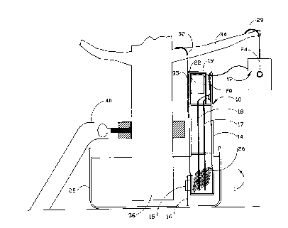
Figure 1 is a cross sectional detail of a detection assembly
mounted on a Christmas tree in accordance with the present
invention;
Figure 2a is a front view of an indicator unit in accordance
with the present invention;
Figure 2b is a side view of an indicator unit in accordance
with the present invention;
Figure 3 is a perspective detail view of a housing used for the
detection unit in accordance with the present invention;
Figure 3a is a partial perspective detail view of an adjustment
rod on the bottom of a detection assembly in accordance with the
present invention; and
Figure 4 is an electronic schematic of a the electronic control
circuit in accordance with the present invention.
Figure 5 is a partial perspective detail view of a detection
unit from a second embodiment of the low water level indicator in
accordance with the present invention.

CA 02249090 1998-09-29
DETAILED DESCRIPTION OF THE PREFERRED EMBODIMENTS
With reference now to the drawings, and particularly to figure
1, there is shown a cross sectional view of detection assembly of
a low water indicator 1 mounted on a Christmas tree . The low water
level indicator 1 includes a detection assembly 10 and an indicator
unit 12. The detection assembly 10 comprises a housing 14, a first
electrode 17, a second electrode 18, and an electronic control
circuit 20. With reference to figure 3, the housing 14 is
preferably molded as a first half housing 19 and a second half
housing 21 which are joined by an adhesive compound, ultrasonic
welding or, any suitable assembly process. With reference to
figure 3, a hook rod 32 is held by a top spring clip 35 which is
disposed at substantially the top of the housing 14. With
reference to figure 3a, an adjustment rod 16 is held by a first
snap retainer 23 molded on the first half housing 19 at
substantially the bottom thereof and a second snap retainer 27
molded on the second half housing 21 at substantially the bottom
thereof . A rod cavity 30 is formed in the length of the first snap
retainer 23 and the second snap retainer 27 to receive the
adjustment rod 16. A plurality of support cavities are positioned
at substantially the bottom of the first half housing 19 and the
second half housing 21. The adjustment rod 16 helps maintain the
height of the housing 14 relative to the bottom of the water
container 28. At least one opening 26 is disposed in substantially
the bottom thereof . The opening 26 allows water which flows inside
the housing to drain into a water container 28. The adjustment rod
6

CA 02249090 1998-09-29
16 is used to adjust the height of the bottom of the housing 14
relative to a water container 28.
The electronic control circuit 20 is mounted in the control
cavity 19 of the housing 14. The control cavity 19 isolates the
electronic control circuit 20 from moisture. The hook rod 32 is
attached to a branch 34 of a tree 36 to provide stability to the
placement of the detection assembly 10. A tree stand 40 is used to
hold the tree 36. The first electrode 17 and the second electrode
18 are fabricated from copper or a copper alloy.
Figure 2a and 2b show the indicator unit 12. The indicator
unit 12 comprises a base 33, and an LED 24. The base 33 may be
molded into any decorative shape, such as an angel, or nothing at
all. The LED 24 is pressed into a hole in the base 33. A hook 29
or other attachment device may be used to fasten the indicator unit
12 to a branch of the Christmas tree 36. Figure 4 shows an
electronic schematic of the electronic control circuit 20. The
first electrode 17 is connected to the positive of the battery 22.
It is preferable that the battery 22 be a nine volt battery. The
second electrode 18 is connected
to the inputs of a first nand gate 42 through a current limiting
resistor 44. The current limiting resistor 44 provides static
protection and prevents false triggering from noise. The current
limiting resistor 44 preferably has a value of 1 megaohms. The
first nand gate 42 is used as a comparator. When current flows
through the first electrode 17 into the second electrode 18 through
the water, the inputs of the first nand gate 42 see a high voltage
7

CA 02249090 1998-09-29
and the first nand gate 42 outputs a voltage low. When the water
level is low, no current is sensed at the inputs to the first nand
gate 42. The grounding resistor 46 pulls the inputs to a voltage
low. The output of the first nand gate 42 is a voltage high.
The output of the first nand gate 42 is connected to an input
of a second nand gate 48. A charging capacitor 50, a charging
resistor 52, and the second nand gate 48 create an oscillator. A
voltage high at the input of the second nand gate 48 causes thereof
to output an oscillating signal. The oscillating signal is used to
drive the LED 24 through a third nand gate 54, a fourth nand gate
56, and a current limiting resistor 58. The LED 24 may also be
solidly lit by connecting the output of the first nand gate 42 to
the inputs of the third nand gate 54, and the fourth nand gate 56.
This connection avoids the oscillation produced by second nand gate
48. Diode 60 is used to protect the first nand gate 42 from static
damage. Capacitor 38 is used to smooth the supply voltage from the
battery 22.
The installation and operation of the low water level
indicator works as follows. The adjustable rod 16 is pushed into
the first snap retainer 23 and the second snap retainer 27 such
that the height of the bottom of the housing 14 is approximately
one inch from the bottom of the water container 28. The hook rod
32 is fastened to a branch 34 of the Christmas tree 36. Then the
top spring clip 35 is squeezed together such that the hook rod 32
slides freely and the adjustable rod 16 contacts the bottom of the
water container 28. The battery 22 is snapped into the battery
8

CA 02249090 1998-09-29
connector 25 and dropped into the top of the housing 14.
The LED 24 will flashing until it is placed into water. The
battery plate is slid into the top of the housing 14. The
indicator unit 12 is hung on an out lying branch of the Christmas
tree 36 or placed in a conspicuous spot. When the water level is
too low, electrical current will no longer pass from the first
electrode 17 to the second electrode 18 through the water. When
current flow ceases between the first electrode 17 and the second
electrode 18, the LED 24 will flash until the water level is
raised.
Figure 5 shows a detection unit 70 from a second embodiment of
a low water level indicator 2. The low water level indicator 2
includes the detection assembly 70 and the indicator unit 12. The
indicator unit 12 used with the low water level indicator 1 may be
with the low water level indicator 2. The detection assembly 70
comprises a housing 72, a first electrode 73, a second electrode
74, and an electronic control circuit 76. The housing 72 is
preferably molded as a first half housing 78 and a second half
housing 80 which are joined by an adhesive compound, ultrasonic
welding or, any suitable assembly process. Preferably, the first
half housing 78 and the second half housing 80 are joined together
such that an air tight seal is formed between the two half
housings. The air tight seal protects the electronic control
circuit 76 from moisture. The housing 72 preferably has an upper
portion 94 and a lower portion 96. A control cavity 86 is disposed
in the upper portion 94 and a electrode cavity 84 is disposed in
9

CA 02249090 1998-09-29
the lower portion 96. The control cavity 86 includes a board
compartment 88 and a battery compartment 90. The electronic
control circuit 76 is placed in the board compartment 88. A
battery 92 is placed in the battery compartment 90. The battery 92
is preferably 9 volts. A 9 volt electrical power supply may also
be used instead of the 9 volt battery 92.
The electrode cavity 84 is disposed within the lower portion
96. The lower portion 96 has a reduced cross section to allow easy
insertion into the water container 28. The first electrode 73 and
the second electrode 74 are disposed in the electrode cavity 84.
The electrodes are preferably fabricated from insulated copper wire
and retained in place by inserting thereof into at least one
slotted projection 98. Sealant 100 such as silicon or the like is
used to seal the control cavity 86 from the moisture in the
electrode cavity 84. At least one opening 82 is disposed in
substantially the bottom of the housing 72. The at least one
opening 82 allows water to flow through the lower portion 96.
At least one eye loop projection 102 extends outward from a top
of the upper portion 94. Tie wraps, string, wire, or any type of
filament 106 may be inserted through the at least one eye loop
projections 102 to attach the detection assembly 70 to a branch 34
of the tree 36. A battery plate 104 is snapped into a battery
plate opening 108 in the housing 72 to retain the battery 92.

CA 02249090 1998-09-29
While particular embodiments of the invention have been shown
and described, it will be obvious to those skilled in the art that
changes and modifications may be made without departing from the
invention in its broader aspects, and therefore, the aim in the
appended claims is to cover all such changes and modifications as
fall within the true spirit and scope of the invention.
11

Representative Drawing
A single figure which represents the drawing illustrating the invention.
Administrative Status

2024-08-01:As part of the Next Generation Patents (NGP) transition, the Canadian Patents Database (CPD) now contains a more detailed Event History, which replicates the Event Log of our new back-office solution.

Please note that "Inactive:" events refers to events no longer in use in our new back-office solution.

For a clearer understanding of the status of the application/patent presented on this page, the site Disclaimer , as well as the definitions for Patent , Event History , Maintenance Fee  and Payment History  should be consulted.

Event History

Description Date
Inactive: IPC from MCD 2006-03-12
Application Not Reinstated by Deadline 2002-02-27
Inactive: Dead - No reply to s.30(2) Rules requisition 2002-02-27
Deemed Abandoned - Failure to Respond to Maintenance Fee Notice 2001-10-01
Inactive: Abandoned - No reply to s.30(2) Rules requisition 2001-02-27
Inactive: S.30(2) Rules - Examiner requisition 2000-10-27
Application Published (Open to Public Inspection) 2000-03-29
Inactive: Cover page published 2000-03-28
Inactive: Single transfer 1999-02-22
Classification Modified 1998-11-30
Inactive: First IPC assigned 1998-11-30
Inactive: IPC assigned 1998-11-30
Inactive: Courtesy letter - Evidence 1998-11-17
Inactive: Filing certificate - RFE (English) 1998-11-12
Filing Requirements Determined Compliant 1998-11-12
Application Received - Regular National 1998-11-10
Request for Examination Requirements Determined Compliant 1998-09-29
All Requirements for Examination Determined Compliant 1998-09-29

Abandonment History

Abandonment Date Reason Reinstatement Date
2001-10-01

Maintenance Fee

The last payment was received on 2000-08-31

Note : If the full payment has not been received on or before the date indicated, a further fee may be required which may be one of the following

  • the reinstatement fee;
  • the late payment fee; or
  • additional fee to reverse deemed expiry.

Please refer to the CIPO Patent Fees web page to see all current fee amounts.

Fee History

Fee Type Anniversary Year Due Date Paid Date
Application fee - small 1998-09-29
Request for examination - small 1998-09-29
MF (application, 2nd anniv.) - small 02 2000-09-29 2000-08-31
Owners on Record

Note: Records showing the ownership history in alphabetical order.

Current Owners on Record
THOMAS, C. KURSEL
Past Owners on Record
ROBERT E. RADKE
THOMAS C. KURSEL
Past Owners that do not appear in the "Owners on Record" listing will appear in other documentation within the application.
Documents

To view selected files, please enter reCAPTCHA code :


To view images, click a link in the Document Description column. To download the documents, select one or more checkboxes in the first column and then click the "Download Selected in PDF format (Zip Archive)" or the "Download Selected as Single PDF" button.

List of published and non-published patent-specific documents on the CPD .

If you have any difficulty accessing content, you can call the Client Service Centre at 1-866-997-1936 or send them an e-mail at CIPO Client Service Centre.


Document
Description 
Date
(yyyy-mm-dd) 
Number of pages   Size of Image (KB) 
Cover Page 2000-03-06 1 44
Abstract 1998-09-29 1 33
Description 1998-09-29 11 406
Claims 1998-09-29 10 279
Drawings 1998-09-29 5 87
Representative drawing 2000-03-06 1 10
Filing Certificate (English) 1998-11-12 1 163
Courtesy - Certificate of registration (related document(s)) 1999-04-07 1 117
Reminder of maintenance fee due 2000-05-30 1 109
Courtesy - Abandonment Letter (R30(2)) 2001-05-08 1 171
Courtesy - Abandonment Letter (Maintenance Fee) 2001-10-29 1 183
Correspondence 1998-11-17 1 29
Fees 2000-08-31 1 29