Note: Descriptions are shown in the official language in which they were submitted.
CA 02249341 2006-03-17
lA
WATER PURIFYING APPARATUS WITH DRINKING WATER FILTER,
REGENERATING DEVICE AND METHOD FOR PURIFYING DRINKING WATER
This invention refers to water purifying apparatus for conditioning drinking
water
from tap water by removing disinfective materials, comprising a casing with a
lid, a
peripheral wall and a bottom, a water input and a water outlet as well
filtering
materials, which are included in casing sections one above the other and are
passed
by tap water to be purified, for removing pollutants, especially chloride,
chlorinated
carbon hydrogen, pesticides, herbicides, insecticides, heavy metals and
nitrates from
tap water in order to prepare drinking water for use in the household.
Especially, this
invention refers to an improved embodiment of water purifying apparatus which
is the
subject matter of EP 483 738 of the same Applicant.
Said known water purifying device for removing pollutants, comprises a casing
with
lid, shell and bottom, the lid of which is provided with a water outlet, the
bottom of
which is provided with a pipe connection to the water inlet, and which
includes
activated carbon and anion exchange materials through which the tap water to
be
purified flows, in the direction from the water inlet to the water outlet for
purified
water, is characterised in that the casing is provided with a lower and an
upper casing
section which are removable from each other, so that the interior of the
casing has a
first lower chamber with activated carbon and a second upper chamber with
anion
exchanging material, that the two chambers each are completed by filter
fleeces at the
top and the bottom, and that the two chambers substantially fill the complete
volume
of the lower and the upper casing sections.
From US Patent 50 61 367 a device with an individual, replaceable filter
cartridge is
known, within which a filter element is provided. Furthermore, filter sections
are
CA 02249341 2006-03-17
1B
provided the filter materials of which are filled into the casing of the
cartridge. If the
loading capacity of the cartridge and/or the remaining filter materials is
exhausted, they are
to be replaced and removed so that the possibility of regeneration does not
exist. The water
inlet is at the top area of the device, the flow of water within the casing is
passed around the
cartridge downwardly, and only then flows through the cartridge.
US-A-47 69 143 discloses a device comprising a cylindrical container with
various
chambers or areas which are in connection with each other and are separated by
intermediate
bottoms. This device does not show any replaceable cartridges. The combination
of the
filter areas is fixed, a regeneration of the filter materials is not possible
so that the filter is to
be destroyed when exhausted. One of the filter areas has been described as
being a filter
cartridge, however, this is not replaceable because the casing is provided
with stationary
intermediate bottoms.
GB-A-212 453 is a filter apparatus with a cylindrical inner wall without any
filter
cartridges, with which the filter material apparently is loosely filled into
the container.
The flow of water in the filter mode is from upwards to downwards, which means
that
the operation is by gravity, and the flow in the regeneration mode is from the
bottom
to top. The filter mode under gravity has considerable disadvantages because
the
filtering effect is very poor and because water channels are formed.
From GB-A-399 514 a water softening is known which comprises a cylindrical
container receiving the softening material, and in the bottom area of which a
perforated metal tube is inserted for supplying tap water. A combination of
replaceable
filter cartridges cannot be derived from this patent. Furthermore,
regeneration also si
based on gravity so that the regeneration effect is insufficient.
CA 02249341 2006-03-17
1C
Compared with this known apparatus, it is an object of the subject invention
to
improve water purifying apparatuses of the forementioned type in such a manner
that
they can be operated in a most simple and useful manner, and with a minimum of
service different filter media and regenerating devices, in order to obtain an
extremely economic solution. Furthermore, it is an object of this invention to
propose
methods for purifying drinking water as well as for regenerating the filters.
According to this invention, these problems are solved by a water purifying
apparatus
which is characterised in that the casing at least on its inner side is of
cylindrical shape
with constant inner diameter, the casing sections are formed as removable and
exchangeable filter cartridges with different filter media and equal outer
diameters
are arranged one above the other within the casing, the individual filter
cartridges are
sealed against the filter casing, and the tap water to be purified is passed
from the
bottom to the top through the filter cartridges.
A method for purifying drinking water from tap water by removing pollutants,
and for
operating a water purifying apparatus according to the subject invention is
characterized in that tap water is passed through various filter media
arranged within
casing sections, wherein the apparatus when operating in the regeneration mode
is
turned upside down in view of the position of the filter mode, above the
apparatus is
arranged a container filled with salt water, which container is connected to
the outlet
of the apparatus so that by gravity or respectively by the bottom to the top,
and the salt
water is discharged at the inlet of the apparatus which is arranged upside
down.
With the proposal according to this invention the cartridges having identical
outer
dimensions and including different filter inedia can be assembled from
prefabricated
CA 02249341 2006-03-17
2
machine parts in any manner according to the filter requirements, being
inserted into
the cylindrical, tubelike filter casing. For inserting and removing the
cartridges, it is
merely necessary to remove the lid of the apparatus. The lid is formed in such
a
manner that if the apparatus is turned upsidedown it can be used as a support
means.
Furthermore, the lid is provided with a handle similar to each of the
cartridges in order
to simplify removal and insertion.
Between the individual cartridges and the filter casing a pressure balance is
required.
Overflow openings are provided within the cartridge casing through which
overflowing water passes into the area between cartridges and filter casing,
which
cannot be rinsed. The overflowing water is exposed to germinate. In order to
oppose
this procedure of germination, means are provided between cartridge and filter
casing
including salt in form of tablets or salt water, which when reacting with the
overflow
water results in a salt solution which prevents germination and sterilizes the
water. For
example, one or several salt tablets can be provided at the peripheral wall of
the
cartridge.
According to a further embodiment of the invention, the drinking water filter
in
addition is provided with a germ diaphragm, by means of which germs can be
filtered.
The germ diaphragm is arranged within a casing which as an additional casing
underneath the filter casing is connected with the filter apparatus. In order
to allow an
exchange of the diaphragm the germ diaphragm casing is formed in such a manner
that it can be opened.
CA 02249341 1998-09-15
3
According to a further embodiment of the invention, the exchangeable filter
cartridges
are arranged within the filter casing in such a manner that they have a
sufficiently large
distance from the inner wall of the filter cases so that they can be rinsed.
In order to regenerate the drinking water filter of the water purifying
apparatus, and to
allow a continuous satisfactory operation, a regeneration device is provided
which
comprises a salt water container arranged above the filter casing or set onto
the lid of
the filter apparatus, a pipe connection between the salt water container and
the bottom
of the filter casing, and a discharge pipe connected with the top area of the
filter
casing, e.g. the lid. By arranging the salt water container in a high position
the salt
water by gravity flows downwards and pushes the salt water fluid through the
cartridges within the filter casing from bottom to top. This results in
regenerating the
ion exchange resins, and the entire content of the drinking water filter is
disinfected by
the natrium solution. The salt water container can also be switched into the
water
circuit in such a manner that switching from normal filter mode to
regeneration mode
will be possible, whereby regeneration can be carried through according to the
counterflow or the uniflow principle. Switching is performed by corresponding
switch-
over valves. For regeneration, the filter casing of the water purifying
apparatus is turned
upside down. Furthermore, with the subject invention the salt container for
the
regeneration process can be built into the water pipe and after completion of
the
regeneration can be separated from the water pipe. This will merely require
exchanging the connections for the water nozzle and the discharge hose.
Another possibility for regeneration is to provide a separate means for
pushing the salt
water into the drinking water filter. Such a device comprises a casing the
container of
which is filled with salt water. The surface of the salt water is covered by a
plate-like or
box-like load so that the weight of this cover acts continuously on the salt
water and
thus, the salt water will be able to flow off with increasing pressure at the
underside of
the container over a discharge, which means that the salt water is then passed
into the
filter casing and flows through the filter cartridges within the filter casing
from the
bottom to the top. This type of device can be used in such a manner that the
water
CA 02249341 1998-09-15
4
purifying apparatus is arranged within the sink, whereas the container filled
with salt
water is arranged adjacent thereto, and at a higher level on the working
surface so that,
in addition to the pressure caused by the weight load the gravity of the salt
water
within the container is used.
Drinking water filters according to the invention can be regenerated by the
consumer
himself. Regeneration is required if
the intake capacity of the nitrate resin is exhausted (e.g. with a nitrate
load of about
100 mg/I and with a discharge amount of approx. 10 I/day regeneration
subsequent to
a nitrate consumption of approx. 10 mg/I is to be recommended which
corresponds to
a period of about eight weeks),
the germ diaphragm is continuously blocked by filtering bacteria and the
decrease in
the through-put e.g. 2,0 I/min. is reduced to a value of e.g. 1,0 I/min.,
the drinking water filter is initially started, furthermore, if the cartridges
or the
diaphragm are exchanged.
Optimum cleaning is obtained by counterflow regeneration. Clogging by
counterflow
is released again and the pollutants which have been collected in the lower
area of the
filter materials are not passed through the entire filter mass unnecessarily.
This
increases the receiving capacity.
When operating in the regeneration mode the nitrate resin is cleaned from
nitrate or
nitride and is disinfected, if required, the activated carbon is also cleaned
and
disinfected, if necessary, the germ diaphragm is freed from bacteria and all
other
bacteria in the pre-chamber are destroyed, whereby the capacity of the through-
put
amount of the diaphragm, e.g. in the amount of 2,0 I/min. is recovered; all
mechanical
filters are cleaned and disinfected, as is also the flint layer.
Disinfecting the filter media resp. the entire filter is of special importance
if the
drinking water filter is used without any germ diaphragm. Subsequent to the
rinsing
operation with water without salt the drinking water filter is reconnected in
the usual
manner to the water pipe.
CA 02249341 1998-09-15
All materials to be used are in line with health standards and are appropriate
for
foodstuffs.
In the following the invention will be described in connection with the
drawings by
various embodiments. The Figures show:
Figure 1 a cross-sectional view through an embodiment of a water purifying
apparatus according to the invention,
Figure 2 a revised embodiment of the water purifying apparatus with
bactericidal
diaphragm,
Figure 3 a further embodiment of a water purifying apparatus according to the
invention,
Figure 4 a revised embodiment of the water purifying apparatus according to
Figure
3 with bactericidal diaphragm,
Figure 5 a further embodiment of the invention with upstream bactericidal
diaphragm,
Figure 6 a water purifying apparatus according to the invention in the
regeneration
mode with salt water container,
Figure 7 a water purifying apparatus of the invention with counterflow
regeneration,
Figure 8 a water purifying apparatus according to the invention with uniflow
regeneration,
Figure 9 a revised embodiment of the counterflow regeneration,
Figure 10 a revised embodiment of the uniform regeneration,
Figure 11 an undertable apparatus in the regeneration condition,
Figure 12 an undertable apparatus in the filter operation condition,
Figure 13 a revised embodiment of an undertable apparatus in the regeneration
condition,
Figure 14 a revised embodiment of an undertable apparatus in the filter mode
condition,
Figure 15 a water purifying apparatus according to the invention in the
counterflow
regeneration mode with pressure container,
CA 02249341 1998-09-15
6
Figure 16 an additional variety of purifying water according to the invention
in the
surroundings of the bactericidal diaphragm, and
Figure 17 the variation according to Figure 16 integrated in a water purifying
apparatus according to the invention.
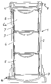
The entire water purifying apparatus is marked with 1. In a cylindrical,
tubelike casing
2 with bottom 3 and removable lid 4 exchangable filter cartridges 5, 6, 6a are
arranged
one above the other. These cartridges are of identical shape and dimensions so
that
they can be exchanged. Between filter casing 2 and cartridges 5, 6, 6a salt
tablets 7 are
arranged e.g. in recesses of the cartridges, which tablets within the space
between filter
casing and cartridges 5, 6, 6a are in contact with water 8 overflowing the
cartridges,
and are dissolved. The resulting salt solution prevents germination of the
overflowing
water so that the water remains free of bacteria. The cartridges 5, 6, 6a are
sealed by
seal rings 9, both in the upper and in the lower area against the filter
casing 2. The
water to be purified enters through an inlet 10 at the bottom 3, flows through
the filter
cartridges 5, 6, 6a from bottom to top, and exist the apparatus through the
outlet 11.
The filter apparatus according to Figure 2 is basically similar to that of
Figure 1,
however, in addition includes a germ diaphragm 12 within a casing 13, which is
arranged underneath the bottom 3 of the filter casing 2, and has an inlet 14,
an outlet
15 and a vent 16. The germ diaphragm casing 13 can be removed from the filter
casing
2 and can be opened for changing the germ diaphragm 12.
With the embodiment of filter 1 according to Figure 3 between the filter
cartridges 17,
18, 19 and the filter casing 2 a flow channel 20 is provided, through which
the
cartridges can be rinsed. Figure 4 shows the filter casing 2 of Figure 3 in
combination
with a germ diaphragm casing according to Figure 2.
With the embodiment according to Figure 5 drinking water flows through a feed-
in
hose 21, a junction coupling 22 and a inlet plug-in portion 23 in the bottom
area into
the filter casing F. The amount of inlet water is reduced by a volume
reduction means
24 to a maximum value of e.g. 2,0 I/min. Within the inlet chamber 25 the
drinking
CA 02249341 1998-09-15
7
water is prefiltered by a layer of silica, whereby coarse suspended particles
are
removed. Subsequent thereto the water flows through a suspended particle
filter 26,
which is made e.g. of plastic fiber wool, and will be cleaned again. The
prefiltered
water passes into a prechamber 27 in which a germ diaphragm 28 e.g. a
Sartopran-PH
distributed by Messrs. Sartorius, Germany with mini-filter means or the like
holds back
all germs or bacteria within the drinking water and filters them, before the
water is able
to flow into the main chamber. Air which may be provided within the prechamber
27
is removed by a ventilation screw 28. The drinking water which in this manner
is free
from suspended particles and bacteria subsequent thereto, is passed into the
main
chamber by series-connected cartridges 29, 30, 31, each of which according to
the
required or necessary degree of purification is filled with different filter
materials, e.g.
activated carbon for the absorption and absorption of plant protective means
and the
like, or with selective nitrate resin for removing nitrate and nitride.
Preferably, all filter
materials are provided with silver granulars which can be regenerated; the
amount of
such granular is chosen so that no silver will be discharged into the drinking
water. The
drinking water filter, therefore, can also be used in surroundings in which
germ
diaphragms can be dispensed with.
The individual cartridges 29, 30, 31 are cylinder-type containers which at the
bottom
and the top are open by permeable plastic grids 33. The lateral walls of the
cartridges
are impermeable. Rinsing the filter materials is prevented by using suspended
particle
filters 34 in the form of plastic fiber wool. Said filters are designed so
that they
compensate volume changes of the filter materials. The cartridge containers
29, 30, 31
are sealed at their lateral walls 35 towards the casing wall by rubber seals
35a so that
an intermediate volume 36 is formed. Before starting the operation of a
drinking water
filter, the pressure within the entire container and the intermediate space 36
is
atmospheric pressure. If the drinking water filter is connected to the water
supply pipe,
during the filling step the pressure in the container is increased up to e.g.
6 bar. For
pressure balance in the intermediate space 36, the cartridges 29, 30, 31 are
provided
with pressure compensating apertures 37. In view of the overpressure no water
flows
into the intermediate space 36 above an amount of maximum 80 ml. In order to
effectively prevent the growing of germs in the intermediate spaces 36,
pockets 38 are
CA 02249341 1998-09-15
8
provided on the outer wall 35 of the cartridges, which pockets are provided
for
receiving salt tablets 39. Said salt tablets 39 are covered by a plastic grid
40, however,
dissolve when being in contact with water within the intermediate space until
a
saturation value of approx. 10 g has been obtained. The resulting salt
solution prevents
the growing of bacteria in the intermediate space 36. In the usual mode of
operation
there is no substantial pressure difference between the container and the
intermediate
space 36.
If the drinking water has flowed through the three cartridges 29, 30, 31 from
the
bottom to the top, it flows through an exit plug-in member 41, a junction
coupling 42,
and a connection hose 43 to the exit fitting. In this way, the filter
operation is
completed. The lid of the drinking water container can be opened by a bayonet
catch
so that the filter cartridges can be inserted into the drinking water
container very easily,
or alternatively the cartridges can be exchanged in a simple manner. The
bottom can
also be opened in order to substitute the germ diaphragms or suspension
filters.
Figure 6 shows a device for regenerating the drinking water filter of the
water purifying
apparatus 1. The drinking water filter is separated from the water connection
pipes 21,
43 by means of junction couplings 22 and 42 and is turned upside down. The
supply
hose 43 is attached to the plug-in member 42 of the salt container 44. The
through-put
water amount is restricted by a reduction means to approx. 0,3 I/min. The
connection
hose 43 of the salt container 44 is connected to the exit plug-in element 41.
The
regenerating hose 21 is connected with the inlet plug-in member 22 at the lid
and is
passed into the discharge channel. As soon as the salt container is filled
with ordinary
cooking salt, the regeneration operation can be performed. The salt water
within the
container 44 is used for regenerating the ion exchange resins provided within
the filter
cartridges 29, 30, 31. Via the hose 43 the salt solution flows through the
inlet 41 of the
lid, which now is the bottom, through the individual cartridges and through
the entire
filter casing upwardly. At the bottom 47, which is now the lid, the salt water
flows via
hose 21 through the exit 22, which otherwise is the inlet.
CA 02249341 1998-09-15
9
A further embodiment of a regeneration system is shown in Figures 7 and 8.
Figure 7
shows a counterflow-regeneration system, Figure 8 a unitlow-regeneration
system. The
filter casing F is similar to that in Figure 5. A salt water container 50 is
switched into
the path of the water pipe 51. Upstream a switching valve 52 is provided which
in the
filter mode passes the water flow via pipe 54 into the inlet 42 of the filter
casing F,
whereas in the regeneration mode the switching valve 52 locks the flow into
pipe 54
and allows the flow into pipe 53 so that the waterstream passes through the
salt water
in container 50, and therefrom into inlet 42. At the outlet 21 a switching
valve 56 is
provided which allows the flow of water in the one position to the water valve
57 and
in the other position to the exit 58. For performing the regeneration mode the
filter
casing is turned upside down.
With a revised embodiment of a regeneration system according to Figures 9 and
10 the
salt water container 59 is connected to the water pipe 60 for the regeneration
mode
only; 61 is a shut-off valve, 62 and 63 are the connection points for
receiving the salt
water container 59. When switching over from filter mode to regeneration mode
the
water valve and the discharge hose at the output 21 of the filter casing F are
merely
reversed.
With an undertable structure of the filter system according to Figures 11 and
12 the
filter casing F is arranged underneath the sink 64. In the regeneration mode
the sink 64
is filled with salt water 65. A hose 66 extends from the bottom of the sink 64
to the exit
valve 67 and through a pipe 68 with the exit 21 of the lid of the filter
casing. The salt
water 65 flows through pipe 68 and into the filter casing F, through the
cartridges from
the bottom to the top (with a filter apparatus turned upsidedown), and from
the inlet 42
which now acts as an exit, through a hose 69 into the sewage channel. In the
filter
mode according to Figure 12 the filter apparatus is operated in the usual
manner,
which means that tap water is passed into the filter casing F through pipe 70
and inlet
42 into the filter casing F, through the cartridges upwardly and at the outlet
21 via the
connection pipe 71 to the outlet valve 67, where the filtered water can be
discharged.
CA 02249341 1998-09-15
Nov.10 '98 12: 10 TEL 00 P. 6
Figures 13 and 14 show the operation of the filter system In the regeneration
conditiori
and in the filter operaing condition, whereby in the regeneration condition
and in the
counterflow-regeneration operation a container filled with salt water is
arranged within
the flushing basin, and the salt water is discharged from the filter system by
means of a
shutoff valve into the sewer, whereas in the fifter operation the supplied
water is
passed from the water conduit via the shutoff valve into the bottom of the
filter system
and can be removed as purified water at the flushing basin.
A further embodiment of a counterflow-regeneration is shown in Fig. 15. The
filter
apparatus F is arranged within the sink 70. A container 45 including salt
water 46 is
arranged on a table plate. Upon the surface of the salt water volume 46 a
casing 47 is
floatingly arranged, which is provided with a load 48 so that pressure is
exerted onto
the salt water volume 46. At the outlet 49 the salt water is supplied through
a hose 71
into the filter casing F and is urged through individual filter cartridges,
and subsequent
thereto at the top (with the filter casing turned upside down) is passed into
the sewer
through a hose 73. The casing 47 within container 45 is designed according to
a float,
is arranged movable in height within container 45, and also is sealed against
the wall
of the container by means of rubber rings 73. Furthermore, casing 47 includes
a
venting tube 74.
For filtering and extracting bacteria and micro-organisms provided within the
raw water
the water purifying apparatus according to the invention is provided with a
bactericidal
diaphragm. As basically shown in Fig. 16, at the outer side of such
bactericidal
diaphragm 75, namely at the filter input, the bacteria will accumulate. Said
bacteria are
destroyed by common salt during regeneration, and are flushed out from the
drinking
water filter casing again. Such regeneration will normally be carried through
only every
4 - 8 weeks. Between said regenerations bacteria can grow through the
bactericidal
diaphragm so that behind the diaphragm an area free of germs can no longer be
guaranted. In order to prevent such growing through the bacteria extracted at
the
bactericidal diaphragm are to be killed as soon as possible, at least within
three days.
For this purpose a niixture for example from copper and zinc in the forni of
so-called
redox granules is inserted into the bactericidal membrane 75 ddwnstream of the
filter
CA 02249341 1998-09-~1t~ p 4
Mov.10 '98 11:15
11
and in front of the bactericidal diaphragm upstream of the filter, as shown
with 77 and
78. With a redox reaction an eiectrolytical current is generated similar to a
battery. The
very low voltage obtained therein causes that the bacteria adhering to the
bactericidal
diaphragm 75 will be destroyed. Therefore, the bacteria can no longer grow
through
the membrane. The process of destroying bacteria is improved by additional
chemical
reactions. As practice has shown, negative results of the water to be filtered
cannot be
made out subsequent to this operation.
Fig. 17 shvws the basic system shown in Fig. 16 built into a water purifying
apparatus
according to the invention.