Note: Descriptions are shown in the official language in which they were submitted.
CA 02249539 1998-10-OS
F&K 111-13-02
- Page 1 -
LOW-IMPACT VACUUM PARTICULATE TRANSFER APPARATUS
This invention deals with vacuum transfer apparatus for grain
and other particulate materials, and more particularly with a
vacuum transfer apparatus for particulate materials which
employs a conveyor discharge to soften the handling of product
by the device.
Vacuums are sometimes used in the place of sweep augers or
other transfer methods to move particulate agricultural
products and other similar goods. Such a vacuum has many
advantages over an auger, not the least of which is safety.
Also, the vacuum does not have a lengthy or complex drive
train or other extensible moving parts which can create
safety, maintenance and manufacturing problems.
Considerable work has been done in the field to increase the
CA 02249539 1998-10-OS
F&K 111-13-02
- Page 2 -
capacity of these vacuum devices to the point that they can
handle the movement of significant bulk quantities of material
in addition to smaller clean-up tasks. Two examples of prior
work in this field are United States Patents 4,662,800 to
Anderson et al. for a "'Grain and Fertilizer Collector" and
4,881,855 to Rempel et al. for a "Vacuum Particulate Transfer
Apparatus"
These two previous patents deal with vacuum collection devices
for particulate materials which are used in agricultural and
other applications. Both of these prior devices employ a
mechanical auger as the means of conveying discharged material
from the device after it is vacuumed up. Anderson et al.
demonstrates a vacuum machine for use in the bulk transfer of
particulate materials which receives materials internally
through a vacuum-generated pickup air stream and mechanically
transfers these particles to a single location at the rear of
the machine via a full-length unloading auger which extends
from front to rear along the bottom of the machine where the
materials can be dumped into another non-connected auger for
further movement, or dealt with in any number of other ways.
Rempel et al. seeks to improve the Anderson et al. device
CA 02249539 1998-10-OS
F&K 111-13-02
- Page 3 -
while still utilizing a combination of vacuum pickup and
mechanical auger unloading technology, by removing the
requirement for two separate augers to handle the discharged
material, as well as by reducing the unintended ingress of
ambient air through the discharge auger by adding a double
door air lock device.
As indicated above, these machines have uses in a broad
section of industries, including agriculture. One of the
advantages of use of these devices has been that the products
handled therethrough are handled on their pickup more gently
than if they were handled by auger or some other method.
However in other applications, as well as in diversifying
agricultural operations producing varied produce of varying
levels of fragility, a limiting factor to the utility of these
devices which has emerged as a problem, and which the present
invention seeks to address, is the continued use of a
mechanical auger as the discharge means for the discharge of
the material from the device once it is vacuumed up.
Specialty seed crops as well as other particulate materials in
agricultural and other applications can be cracked or
otherwise degraded by mechanical augering and as such it is
the obj ect of the present invention to provide a vacuum device
CA 02249539 1998-10-OS
F&K 111-13-02
- Page 4 -
which removes the mechanical auger from the discharge function
of the vacuum apparatus.
SUN~ARY OF THE INVENTION
As outlined above, it is the object of the present invention
to provide a vacuum particulate transfer apparatus such as
those known in the art which replaces the mechanical discharge
augers currently employed thereon with an alternative
discharge method.
Specifically, it is the object of the present invention to
provide a vacuum particulate transfer apparatus such as those
known in the art which replaces the mechanical discharge auger
with a belt conveyor.
The invention, a low-impact vacuum particulate transfer
apparatus, accomplishes its objects comprising substantially
a suction mechanism with an inlet and an outlet, a pick-up
conduit attached to the inlet and through which materials may
be directed into the suction mechanism, and a belt conveyor
operably coupled with the outlet and by which materials
CA 02249539 1998-10-OS
F&K 111-13-02
- Page 5 -
transferred to the outlet through the suction mechanism can be
moved to a remote location.
Many embodiments of the suction mechanism can be contemplated,
all of which would work with the basic concept of the present
invention, namely to provide a belt conveyor discharge on a
conventional particulate vacuum device.
It is foreseeable that an airlock might be also added to
various embodiments of the suction mechanism at the outlet
where it joins the belt conveyor, for the purposes of sealing
the belt conveyor against the substantial entry of ambient air
during operation of the conveyor and the suction mechanism, in
order to prevent the significant diminution of the strength of
the airstream created by the suction mechanism.
Various embodiments of the present invention might also have
a mobile chassis added, whereby the device in its entirety
could be moved and positioned adjacent to materials to be
transferred.
Variations could also be made on the belt conveyor, including
building the belt conveyor into more than one section, which
CA 02249539 1998-10-OS
F&K 111-13-02
- Page 6 -
sections could be folded together for the purpose of
transporting the device. Alternatively, the belt conveyor
also might be rendered removable from the remainder of the
apparatus for transport.
A rubber conveyor belt or other chain or belt apparatus could
be used in the belt conveyor.
Cleats could be added to the belt conveyor to assist in the
carriage of materials by the belt conveyor, as well as such
cleats possibly acting in the role of an airlock device.
The belt conveyor may or may not include a housing.
DESCRIPTION OF THE DRAH1INGS:
While the invention is claimed in the concluding portions
hereof, preferred embodiments are provided in the accompanying
detailed description which may be best understood in
conjunction with the accompanying diagrams where like parts in
each of the several diagrams are labelled with like numbers,
and where:
CA 02249539 1998-10-OS
F&K 111-13-02
- Page 7 -
Figure 1 is a drawing of a conventional apparatus known
in the field, employing a screw-auger discharge means;
Figure 2 is a perspective drawing of one embodiment of
the apparatus of the present invention, showing the belt
conveyor discharge means;
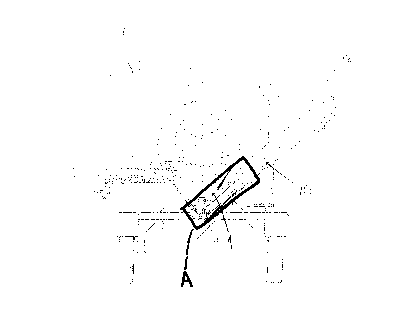
Figure 3 is a detail of area "A" from Figure 2; and
Figure 4 shows the embodiment of Figure 3 with the
addition of cleats to the belt.
DETAILED DESCRIPTION OF THE ILLUSTRATED EMBODIMENTS:
Referring to Figure 1, there is shown a conventional vacuum
device for use in the cleanup or transfer of particulate
materials. The device includes a suction apparatus 1 having
an inlet 2 and an outlet 4. There is in this case an intake
hose 3 through which particulate material can be vacuumed into
the device. Attached to the outlet 4 of the suction apparatus
is a conventional screw auger 7 extending to a remote point 5,
which auger 7 carries the particulate material from the
CA 02249539 1998-10-OS
F&K 111-13-02
- Page 8 -
suction apparatus 1 once it is vacuumed into the apparatus won
the end deposited in the auger 7. The auger 7 treats the
particulate material rather harshly as it is conveyed to the
remote point 5. In the embodiment shown, that conventional
device has a folding auger 7 which can be doubled back on
itself for transportation of the device. Also shown in that
Figure is the addition of a transportable frame 6 to the
suction device itself which again allows for the
transportation of the device as a whole from place to place.
The present invention consists of such a conventional vacuum
device, wherein the auger discharge is replaced by a belt
conveyor. It will be understood that there are many
conventional methods of building a belt conveyor, all of which
are contemplated within the scope of the present invention.
The following description, and Figures 2 to 4, demonstrate one
particular belt conveyor, but it will be understood that any
such belt conveyor which accomplishes the same function as
those shown and described herein are contemplated within the
scope of the present invention.
Referring now to Figure 2, an embodiment of the present
invention is shown. There is shown a suction mechanism 1 such
CA 02249539 1998-10-OS
F&K 111-13-02
- Page 9 -
as those used in the art, said suction mechanism 1 having an
inlet 2 and an outlet 4. There is a pickup conduit 3 attached
to inlet 2 and through which materials will be directed into
the suction mechanism 1 when the suction mechanism 1 is
engaged. Materials vacuumed into the suction mechanism 1 via
the pickup conduit 3 art deposited at the outlet 4. There is
demonstrated in this Figure a belt conveyor attached to the
suction mechanism 1 at the outlet 4, which belt conveyor will
care re-particulate material vacuumed into the suction
mechanism 1 away from the mechanism 12 a remote location. The
belt conveyor shown consists of a belt 9 looped between a
drive roller 8 and a terminal roller 11.
The belt conveyor in the embodiment demonstrated is encased in
a housing which will confine material being conveyed by the
belt conveyor to the belt 9. It will be understood, however,
that such housing could be modified in various ways or
possibly even removed, so long as material being conveyed by
the belt 9 would be confined thereto in some manner.
The belt 9 can be driven in the direction shown by applying
rotary power to the drive roller 8. Particulate material
deposited on the moving belt 90 then be carried along the belt
CA 02249539 1998-10-OS
F&K 111-13-02
- Page 10 -
to the terminal roller 11 where it will be deposited.
Handling of the material by this belt rather than by a screw
auger will provide much gentler handling of the material, less
breakage and allow for the use of the device with more fragile
materials.
It is particularly contemplated that a rubber belt would be
used as the belt 9 but it will also be obvious to one skilled
in the art that the invention could be practiced using a steel
belt or a belt made from some other alternative material and
that all such belts are contemplated within the scope of the
present invention.
Also shown in the embodiment of Figure 2 is a mobile chassis
6 allowing the device as a whole to be positioned adjacent to
materials to be handled. The chassis 6 in this case comprises
a frame, axles and wheels along with a hitch. It will be
understood that other types of chassis could also be used and
are all also contemplated within the scope of the present
invention. As well, the device could be used without a mobile
chassis and as such the inclusion of the chassis is not
intended to limit the broadest embodiments of the present
invention as claimed, as it will be obvious to one skilled in
CA 02249539 1998-10-OS
F&K 111-13-02
- Page 11 -
the art that the patentable aspect of the present invention is
the substitution of the belt conveyor for the mechanical screw
auger used in similar devices to date.
Demonstrated in Figure 2 is another optional aspect of the
present invention. The belt conveyor could be rendered more
easily transportable by building it in more than one section,
hinged together such that the sections could be folded back
together for transport purposes. Yet another alternative to
render the device as a hold more transportable would be to
make the entire belt conveyor section of the unit removable,
simply with clamps or the like which could removably clamp the
belt conveyor to the outlet 4. The entire belt conveyor could
then the removed for the purpose of transport and reattached
when the device was repositioned.
Also demonstrated are intermediate rollers 10 which will
support the belt 9 along its travel. It will be understood
that the intermediate rollers may not be essential to the
operation of the belt conveyor and as such embodiments of the
invention using a belt conveyor without intermediate rollers
are contemplated within the scope of the present invention.
CA 02249539 1998-10-OS
F&K 111-13-02
- Page 12 -
Figure 3 shows a detail of the area marked "A" in Figure 2.
Figure 4 demonstrates the addition of cleats 14 to the belt 9.
The cleats 14 are flexible rubber and as such can be built so
that they travel in an upright position with the belt along
its delivery route, and once they reach the terminal roller if
there is a housing in place the flexible cleats can bend back
if necessary, to be confined inside the housing beneath the
belt until they come back to the drive roller 8 position where
they can assume their upright position again and transport
more material up the belt. The cleats 14, if positioned
properly, could also act as an airlock to substantially sealed
the belt conveyor against the substantial entry of ambient air
during the operation of the belt conveyor and the suction
mechanism 1 in order to prevent the significant diminution of
the strength of the airstream created by the suction mechanism
1.
It will also be understood that various other air locks might
be used to protect the outlet 4 against the substantial entry
of ambient air during the operation of the invention, in order
to prevent a significant diminution of the strength of the
airstream created by the suction mechanism 1, and that such
CA 02249539 1998-10-OS
F&K 111-13-02
- Page 13 -
other air locks would also be contemplated within the scope of
the present invention.
In operation then, the suction mechanism 1 and the belt
conveyor would be started. The pickup conduit 3 would be
directed to the material to be transported. Material would be
vacuumed into the suction mechanism 15 at the outlet 2 and the
pickup conduit 3, said material then being deposited at the
outlet 4. At the outlet 4, the material would be deposited
onto the belt 9 and carried along the belt conveyor to the
terminal roller 11 where it would be deposited.
The foregoing is considered as illustrative only of the
principles of the invention. Further, since numerous changes
and modifications will readily occur to those skilled in the
art, it is not desired to limit the invention to the exact
construction and operation shown and described, and
accordingly, all such suitable changes or modifications in
structure or operation which may be resorted to are intended
to fall within the scope of the claimed invention.