Note: Descriptions are shown in the official language in which they were submitted.
CA 02249921 1998-10-09
MODULAR SHORING FRAME AND SYSTEM
Field of the Invention
This invention relates to support frames for shoring poured concrete slabs. In
particular, this invention relates to modular shoring frames and post shores
for temporarily
supporting poured concrete floors.
Background of the Invention
It is common practice in the construction industry to shore newly poured
concrete slabs with a temporary support frame. For large slabs, such as those
forming
building floor structures, a number of shoring frames must be used. Generally,
the support
frames remain in place until the slab has cured sufficiently to allow the safe
removal of the
frame(s). Prior art shoring frames have generally comprised a pair of legs
that are laterally
spaced apart and interconnected by suitable bracing members, such as
horizontal ledgers.
The bracing members are welded, or otherwise permanently fixed, to the legs.
Typically, the
legs have screwjacks at one or both ends which can be adjusted to fix the
height of the frame
to the desired height of the slab.
When it is desired to pour a concrete a slab, a number of spaced apart frames
are generally interconnected to form a shoring tower. The frames must be
lifted into place
and cross braces are generally secured between adjacent frames to interconnect
the frames to
form a tower. To the top of each leg in the tower can then be secured cross
beam joists that
support a slab form or concrete mold. The screwjacks are then adjusted until
the structure is
level, at the appropriate height, and securely supported at all points. Once
the concrete has
been poured, the tower remains in place for several days, or longer, until the
slab has set.
Each supporting tower is then disassembled in the reverse order of the
assembly and removed
from the site, or to another location. Commonly owned U.S. Patent No.
4,470,574 discloses a
typical prior art shoring frame and tower system.
The shoring towers or structures of the prior art have several disadvantages.
The frames are large and unwieldy since they are welded as one piece and not
adjustable.
Depending on their height, it may take two or more people to place or remove
them. The
CA 02249921 1998-10-09
2
frames serve only one function. If single post shores are needed for reshoring
the slab, they
must be provided separately, and be transported to the site and separately
installed after the
frames and/or towers have been disassembled. This adds to the cost of
constructing concrete
slabs by requiring separate shoring components for shoring frames and single
post shoring.
Summary of the Invention
It is an object of the present invention to provide a novel shoring frame and
shoring system which obviates or mitigates the disadvantages of the prior art.
It is desirable to provide a shoring structure which can be assembled and -
disassembled on site. It is further desirable to provide a shoring structure
which is assembled
from multi-use components.
In a first embodiment the present invention provides a structure for shoring a
concrete slab, comprising
at least two post shores having T-bolt channels running vertically along at
least a portion of their length;
at least one frame member having means to slidingly engage said T-bolt
channels;
releasable fastening means for lockingly connecting said frame member to said
T-bolt channels to form a frame assembly; and
slab support means supportingly received by said frame assembly;
wherein said shoring structure is demountable.
Brief Description of the Drawings
Preferred embodiments of the present invention will now be described, by
way of example only, with reference to the attached Figures, in which:
Fig. 1 shows a perspective view of a modular shoring frame in accordance
with the present invention;
Fig. 2 shows an exploded perspective view of portion "A" of Fig. 1;
Fig. 3 shows a perspective view of portion "B" of Fig. 2;
Fig. 4 shows a perspective view of a T-bolt;
CA 02249921 1998-10-09
3
Fig. 5 shows the T-bolt of Fig.4 in an unlocked position; and
Fig. 6 shows the t-bolt of Fig. 4 in a locked position.
Detailed Description
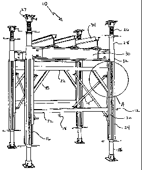
Referring to Figure 1, the shoring structure 10 of the present invention is
illustrated. The shoring structure 10 generally comprises frame assemblies 12
and bracing
members 14. Bracing members 14 interconnect the frame assemblies 12 to provide
an
assembled shoring structure 10.
Frame assemblies 12 generally consist of vertical post shores 16 laterally
spaced apart by a demountable ledger member 18. Ledger member 18 has vertical
sidebars
20 adapted to connect to post shores 16, as will be more fully explained
below. Vertical
sidebars 20 are spaced apart by ledgers 22. Angle braces 23 give added
strength and
rigidity to ledger member 18. Ledgers 22 are conventionally vertically spaced
two to six
feet apart.
Post shore 16 generally consists of a T-bolt channel member 24 surmounted
by screwjack assemblies 26 at one or both ends. Extension tubes 28 can replace
or
supplement the screwjack assemblies 26. As will be understood by those of
skill in the art,
the length of a post shore 16 can be extended by joining two or more T-bolt
channel
members 24 end to end with appropriate couplers. T-bolt channel members 24 can
be
supplied in various lengths, generally up to sixteen feet. With the addition
of extension
tubes 28 and screwjack assemblies 26, it is possible to provide single post
shores 16 up to
twenty-four feet in length without compromising strength or rigidity.
A saddle beam 30 spans the distance between post shores 16. The saddle
beam 30 has sleeves 32 at either end which have an inner diameter adapted to
fit over
extension tubes 28, and which are supported by the upper edge of T-bolt
channel member
24. As will be understood by those of skill in the art, saddle beams 30 enable
a soffit of
the drop beams to be supported at one level and the slab at another level,
thus enabling the
slab support to be removed without disturbing the support under the drop
beams.
CA 02249921 1998-10-09
4
Extension tubes 28 can be installed at the top or bottom of the post shores
16. This can result in a significant reduction of the number of screwjack
assemblies 26
required for a specific application. Consequently, there is a more efficient
utilization of
equipment and attendant cost reductions. Levelling, or adjusting the height,
of a post shore
16 is less time consuming and more accurate than adjusting height with
screwjacks 26
alone, especially when used on flat level concrete.
Extension tube plates 27 secure the ends of the extension tube 28 or the post
shore 16 to conventional aluminum stringers when a screwjack 26 is not
required.
As will be understood by those of skill in the art, when shoring structure 10
is assembled, beam joists 34, or other structural support members, can then be
supported
across saddle beams 30, as illustrated, and/or across the upper surface of
post shores 16.
Referring to Figures 2 and 3, a portion of the frame assembly 12, marked
"A" in Fig. 1, is illustrated. T-bolt channel member 24 has four outwardly
extending T-
bolt channels 36. Figure 3 shows, in greater detail, T-bolt channel member 24.
Vertical
sidebar 20 is provided with an overlapping channel 38 which is adapted to
slidingly engage
with T-bolt channel 36. Vertical sidebar 20 is releasably connected to the T-
bolt channel 36
using conventional T-bolt fasteners 40 which are inserted through apertures 41
in sidebar
20 to engage T-bolt channel 36.
As shown in Fig. 4, the T-bolt fastener 40 comprises a bolt 42 having a head
44 having a width 46 substantially equal to an opening 48 of T-bolt channel
36. Head 44
has a length 50 approximately the inner width 52 of T-bolt channel 36. In this
manner, the
head 44 can be inserted in the channel 36 anywhere along the length thereof,
twisted 90 ° to
engage the overlapping edges of channel 36, and locked therein by tightening
the nut 54
along the thread of the T-bolt 42.
Figs. 5 and 6 shown the T-bolt fastener 40 in an unlocked and locked
engagement, respectively. As will be noted, the opposite rounded corners 56
and sharp
corners 58 restrict head 44 to movement in the direction of the arrow within
channel 36.
CA 02249921 1998-10-09
In use, shoring structure 10 is assembled using well known construction
techniques. The ledger members 18 are connected to post shores 16 by inserting
the heads
44 of T-bolt fasteners 40 through apertures 41 of sidebars 20. The bolt 42 is
rotated 90
for retaining therein and nut 54 threadingly engages the T-bolt 40, firmly
fastening the
ledger member 18 to post shore 16. The frame assemblies 12 thus constructed
are then
positioned and angle braces 14 are used to interconnect two or more frame
assemblies 12 to
form a tower structure. Saddle beams 30 and beam joists 34 can then be
installed and the
structure can be adjusted to the correct height by turning conventional
screwjacks 26.
Structure 10 can be disassembled in the reverse order. If desired, post shores
16 can be
left in place when disassembling structure 10. The remaining components of
structure 10
can be re-used elsewhere.
As will be appreciated, the provision of four T-bolt channels 36 on T-bolt
channel member 24 allows other frame assemblies 12, or other components, to be
attached
to channel member 24. In this manner, a larger structure 10 can be assembled
as desired.
As is apparent, the required floor space for erecting a structure 10 is
minimized. Shoring structure 10 can be made of aluminum to reduce the weight
of the
structure without sacrificing strength. The structure 10 can achieve safe
working loads up
to 22,700 kg per frame assembly 12 at a safety factor of 2:5:1, or as high as
27,000 kg. at
a safety factor of 2:1. Transportation, storage, assembly, disassembly and
handling cost
are reduced due to the light weight, modular nature, and mufti-use features of
the structure
and its various components.
Further advantages of the present invention will be apparent to those of skill
in the art. The post shores can be used to form the legs of the shoring
structure, or
separately as single post shores. The post shores can also be extended to
easily build
higher towers for supporting slabs at greater heights. Since the components of
the shoring
structure are made from extruded high strength aluminum, a single person can
generally
transport and erect a post shore with heights of 20 feet or more. The high
strength of the
resulting support structures also means that less bracing is required than in
conventional
structures. This can cause less congestion on a work site. The multiple T-bolt
channels on
CA 02249921 1998-10-09
6
the legs can make it simple to create towers of different shapes and sizes. In
addition,
supplementary bracing can be added to a tower or to a single post shore by
attaching braces
to the T-bolt channels.
It will be apparent to those skilled in the art that the foregoing is by way
of
example only. Modifications, variations and alterations may be made to the
described
embodiments without departing from the scope of the invention which is defined
solely in the
claims.