Language selection

Search

Patent 2249953 Summary

Third-party information liability

Some of the information on this Web page has been provided by external sources. The Government of Canada is not responsible for the accuracy, reliability or currency of the information supplied by external sources. Users wishing to rely upon this information should consult directly with the source of the information. Content provided by external sources is not subject to official languages, privacy and accessibility requirements.

Claims and Abstract availability

Any discrepancies in the text and image of the Claims and Abstract are due to differing posting times. Text of the Claims and Abstract are posted:

  • At the time the application is open to public inspection;
  • At the time of issue of the patent (grant).
(12) Patent: (11) CA 2249953
(54) English Title: TAMPER-EVIDENT CONTAINER CLOSURE
(54) French Title: FERMETURE DE CONTENEURS INVIOLABLE
Status: Expired and beyond the Period of Reversal
Bibliographic Data
(51) International Patent Classification (IPC):
  • B65D 50/02 (2006.01)
  • B65D 25/32 (2006.01)
  • B65D 43/02 (2006.01)
  • B65D 43/06 (2006.01)
(72) Inventors :
  • CONTI, RINO (United States of America)
(73) Owners :
  • PLASTICAN, INC.
(71) Applicants :
  • PLASTICAN, INC. (United States of America)
(74) Agent: MACRAE & CO.
(74) Associate agent:
(45) Issued: 2005-08-30
(22) Filed Date: 1998-10-09
(41) Open to Public Inspection: 1999-06-19
Examination requested: 2000-10-12
Availability of licence: N/A
Dedicated to the Public: N/A
(25) Language of filing: English

Patent Cooperation Treaty (PCT): No

(30) Application Priority Data:
Application No. Country/Territory Date
994,536 (United States of America) 1997-12-19

Abstracts

English Abstract


A tamper-evident closure for a container is provided. The container is
formed with means at its open upper end for making a snap fit locking
connection with a cover. The container has a peripheral flange with a skirt
section that surrounds and is spaced radially from the container's side wall,
and
the cover has a depending skirt that extends down around the upper end of the
container and has a free bottom edge that lies immediately adjacent to the
flange. The flange has an outer surface that is flush with the adjacent
portion of
the outer surface of the skirt, so that essentially the flange appear to be a
continuation of the skirt. As a consequence the closure formed by the cover
(lid)
and the container is resistant to opening by a small child. Additionally the
skirt
section of the flange has a tab portion that is breakable under pressure so
that,
once broken, it can be depressed inwardly toward the container side wall far
enough to permit a person to engage the bottom edge of the skirt on the cover
and thereby force the cover off of the container. The tab portion functions as
a
tamper evident feature, since the fact that it has been broken can be easily
discerned from inspection and since the torn tab cannot be restored to its
original condition.


Claims

Note: Claims are shown in the official language in which they were submitted.


11
WHAT IS CLAIMED IS:
1. A covered container with a tamper evident closure, said
covered container comprising, in combination a cover and a container;
said cover including a circular body section and a circular rim
section, said rim section including means for locking said cover to said
container and a depending skirt;
said container having an open top end and comprising a
bottom wall and a side wall together defining a predetermined volume, said
side wall having a bottom end formed integral with said bottom wall and a
top end that is releasably and lockingly engaged with said means for
locking the cover to said container, said side wall also having an integral
outwardly and circumferentially extending flange that is spaced from said
top end;
said flange including (a) a ring section that is formed integral
with and projects radially from said side wall and (b) a skirt section that is
formed integral with and depends from said ring section in surrounding
spaced relation with said side wall;
said depending skirt of said cover having outer and inner
surfaces and terminating in a bottom edge, said skirt extending down a
distance such that its said bottom edge is adjacent said ring section of said
flange;
said ring section surrounding said side wall and having top
and bottom surfaces and first and second ends that are spaced
circumferentially from one another so as to define a circumferentially
extending gap between said first and second ends;
said skirt section of said flange having an outer surface that is
substantially flush with said outer surface of said skirt of said cover, said
skirt section also having a top end and a bottom end, with said top end
joined to said ring section, and first and second frangible score lines formed


12
in said skirt section, said first and second score lines intersecting the
plane
of said top surface of said ring section between said first and second ends
of said ring section, said score lines each extending from said top end of
said skirt section toward said bottom end of said skirt section and
terminating adjacent to said bottom end so as to define a tab portion of said
skirt section, said skirt section being breakable along said score lines when
pressure is applied to said tab portion in the direction towards said side
wall, thus providing a visual indication of tampering, whether authorized or
unauthorized, and allowing a person to engage the bottom edge of said
skirt between said first and second ends of said ring section so as to
facilitate removal of said cover from said container.
2. A covered container according to claim 1 wherein said score
lines are formed in the outer surface of said flange skirt section.
3. A covered container with a tamper evident closure, said
covered container comprising, in combination a container and a cover;
said cover including a body section and a rim section
surrounding said body section, said rim section including means for
releasably locking said cover to said container and a depending skirt
terminating in a bottom edge and having inner and outer surfaces;
said container having an open top and comprising a bottom
wall and a side wall together defining a predetermined volume, said side
wall having a bottom end formed integral with said bottom wall and a top
end that is adapted to make a locking engagement with said means for
releasably locking said cover to said container, said side wall also having
an integral circumferentially-extending flange spaced from said open top;
said circumferentially-extending flange including (a) a radially
projecting ring section that is formed integral with and extends around said
side wall, and (b) a depending skirt section that is formed integral with said


13
ring section and extends around and is spaced from said side wall, said
skirt section having inner and outer surfaces and an outer diameter
adjacent said ring section that is substantially the same as the outer
diameter of said skirt at said bottom edge;
said skirt extending below said body section a distance such
that its said bottom edge terminates adjacent to said ring section of said
flange, whereby said outer surface of said skirt and said outer surface of
said skirt section are substantially flush with one another at the junction of
said bottom edge and said ring section of said flange;
said ring section having top and bottom surfaces and at least
one hole that extends through said top and bottom surfaces, said at least
one hole having first and second circumferentially spaced ends;
said skirt section having a top end and a bottom end, with said
top end joined to said ring section, and first and second frangible score
lines formed in said skirt section, said first and second score lines
intersecting the plane of said top surface of said ring section substantially
in
line with said first and second circumferentially spaced ends of said hole,
said score lines each extending from said top end toward said bottom end
of said skirt section and terminating adjacent to said bottom end so as to
define a tab portion of said skirt section, said skirt section being breakable
along said score lines when pressure is applied to said tab portion, thus
providing a visual indication of tampering, whether authorized or
unauthorized, and allowing a person to engage the bottom edge of said
skirt between said first and second ends of said hole so as to facilitate
removal of the cover from the container.
4. A covered container according to claim 3 wherein said score
lines are spaced from one another a distance equal to or less than the
distance between said first and second ends of said hole.

14
5. A covered container according to claim 3 wherein said score
lines are formed in said outer surface of said skirt section of said flange.
6. A covered container according to claim 3 further including a
plurality of mutually spaced radially extending support webs formed integral
with and extending between said inner surface of said skirt section and said
outer surface of said container side wall.
7. A covered container according to claim 6 having one of said
support webs located adjacent to each end of said tab section.
8. A covered container according to claim 3 wherein said upper
surface of said ring section is flat.
9. A covered container according to claim 3 wherein said
container side wall is tapered, having a larger outer diameter at said top
end than adjacent said bottom wall.
10. A covered container according to claim 3 wherein said skirt is
spaced radially from said body section of said cover so as to form a channel
therebetween, said means for locking said cover to said container is formed
in said channel, and said top end of said container extends into said
channel for engagement with said means for locking said cover to said
container.
11. A covered container according to claim 10 wherein said
means for locking said cover to said container comprises at least one
locking rib on the inner surface of said skirt that reduces the width of said
channel adjacent the junction of said rim and said body section of said
cover, said top end of said container side wall has at least one mating bead


15
formed integral with and extending circumferentially along its said top end,
the thickness of the top end of said side wall at the location of said at
least
one mating bead being greater than the width of said channel at the
location of said at least one locking rib, and said cover being made of a
flexible resilient plastic material so that said cover can be attached to said
container by a snap-type locking action characterized by flexing of said
cover so that said channel (a) first expands in width to permit said at least
one locking rib to pass over and by said at least one mating bead and (b)
then contracts in width so as to cause said at least one locking rib to grip
said at least one mating bead, thereby releasably locking said cover to said
container.
12. A covered container according to claim 3 further including a
handle pivotally secured to said skirt section of said flange at two
diametrically opposed locations.
13. A covered container according to claim 12 wherein said skirt
section has two diametrically opposed keyhole slots, the opposite ends of
said handle carry pivot shafts that are rotatably mounted in said keyhole
slots, and further including means attached to said pivot shafts for
preventing said pivot shafts from being pulled axially out of said keyhole
slots.
14. A covered container according to claim 3 wherein said tab
portion is bendable inwardly toward said side wall to a selected position
when said skirt is broken along said score lines, and further including detent
means engageable by said tab portion for holding said tab portion in said
selected position.

16
15. A covered container with a tamper evident closure, said
covered container comprising in combination a plastic cover and a plastic
container;
said cover comprising a body section and a surrounding rim
section, said rim section including a depending skirt that terminates in a
bottom edge and first locking means on said skirt for securing said cover to
said container;
said container comprising a bottom wall and a side wall
together defining a predetermined volume, said container having an open
end opposite to said bottom wall, said side wall having second locking
means at said open end for engaging said first locking means so as to
releasably lock said cover to said container and thereby close off said open
end of said container;
said container also having a flange formed integral with and
surrounding said side wall adjacent to but spaced from said open end, said
flange comprising a ring section that extends radially outward from said side
wall and a depending skirt section that is spaced from said side wall and
extends from said ring section in a direction generally lengthwise of said
container, said skirt section having a first end at its junction with said
ring
section and a second end remote from said ring section, said skirt section
also having a partially rupturable tab portion defined by and extending
between two mutually spaced frangible areas each extending from said first
end toward said second end of said skirt section, said frangible areas
terminating adjacent to but spaced form said second end of said skirt
section, and said ring section being interrupted in the region corresponding
in position to said rupturable portion of said skirt section so that said
rupturable portion is unsupported by said ring section;
said ring section having an outer diameter that is substantially the
same as the outer diameter of said skirt at said bottom edge and being
disposed such that said bottom edge of said skirt is adjacent said ring


17
section of said flange when said cover is locked to said container by said
first and second locking means, whereby said cover may be removed
without the use of a tool by rupturing said skirt section along said two
frangible areas so that said rupturable portion can be depressed inwardly
toward said side wall far enough to permit said bottom edge of said skirt to
be manually grasped for pulling the cover away from said container, the
rupturing of said skirt section being readily apparent by visual inspection.
16. A container with a tamper-evident closure according to claim
15 wherein said tab portion is bendable inwardly toward said side wall to a
selected position when said skirt section is ruptured along said two frangible
areas, and further including detent means on said ring section engageable
by said tab portion for holding said tab portion in said selected position.
17. A container with a tamper-evident closure according to claim
15 wherein said cover and container are locked together in a snap-type
connection.

Description

Note: Descriptions are shown in the official language in which they were submitted.


CA 02249953 1998-10-09
IN THE UNITED STATES PATENT AND TRADEMARK OFFICE
TAMPER-EVIDENT CONTAINER CLOSURE
Field Of The Invention
The present invention pertains to provision of a container with a tamper
evident closure that also is resistant to opening by a small child.
Prior Art
Heretofore efforts have been made to provide containers with child resistant
closures, i.e., closures that are difficult for children to open. this in the
case
where the closure involves a removable lid or cover, the combination of
container and lid or cover is designed so a small child cannot effect removal
of
the lid or cover from the container.
Also known are efforts to make containers with tamper-evident closures, i.e.,
closures that are designed to indicate that they have been tampered with.
Child resistant and tamper evident lids are especially important in the case
of
containers for over the counter and prescription drugs. A variety of different
closures designs have been patented and used, some specifically for relatively
small containers ahd others for containers of moderate or large size. Each
known closure design has its own advantages and limitations. Examples of
child resistant and tamper-evident closures are provided by U.S. Patents Nos.
5,411,160, issued 2 May 1995 to Goulet et al for Child Resistant Closure, and
5,224,617, issued 6 July 1993 to M. Gaudrealt for Tamper Evident Container,
and the prior art patent documents cited therein.

CA 02249953 1998-10-09
2
Obiect And Summary Of The Invention
A primary object of the present invention is to provide a novel tamper-evident
closure for plastic containers.
Another primary object of this invention is to provide a novel child-resistant
closure for plastic containers.
A further object is to provide plastic containers having a novel closure
design
that is both child resistant and tamper evident.
The foregoing objects, and other objects stated in or rendered obvious by the
following specification are achieved by providing (1 ) a container having a
peripheral flange and (2) a cover or lid that fits over and makes a snap-fit
connection with the open top end of the container, the cover or lid having a
depending skirt that abuts the peripheral flange and has an outer surface that
is
flush with the adjacent portion of the outer surface of the flange, so that
essentially the flange appear to be a continuation of the skirt. As a
consequence the closure formed by the cover (lid) and the container is
resistant
to opening by a small child. Additionally the flange has a tab portion that is
breakable under pressure so that, once broken, it can be depressed inwardly
toward the container side wall far enough to permit a person to engage the
bottom edge of the skirt and thereby force the cover off of the container. The
tab
portion functions as a tamper evident feature, since the fact that it has been
broken can be easily discerned from inspection and since the torn tab cannot
be
restored to its original condition. Other features and advantages of the
invention are obvious from the following detailed description of a preferred
embodiment of the invention which is to be considered together with the
accompanying drawings.
The Drawincts

CA 02249953 2004-06-23
3
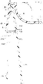
Fig. 1 is an exploded side view showing a container and lid embodying the
present invention, with portions show in cross-section;
Fig. 2 is a side elevation of the same container rotated 90° from the
view of
Fig. 1;
Fig. 3 is a fragmentary cross sectional and exploded view illustrating details
of the container and the handle that permit the handle to make a removable
pivotal connection to the container;
Fig. 4 is a fragmentary perspective view showing details of the tab portion of
the flange on the container; and
Fig. 5 is a sectional view in elevation illustrating how the tab portion can
be
ruptured and pushed inwardly to facilitate removal of the lid.
In the several figures, like numerals designate like components.
DESCRIPTION OF PREFERRED EMBODIMENT
Referring first to Figs. 1 and 2, the illustrated embodiment comprises a lid
or
cover 2 and a container 4, both preferably molded of a resilient plastic such
as
polyethylene. However they may be made of some other plastic material so long
as the lid has adequate flexibility and resiliency to permit it to be applied
to the
container by a snap fit connection. By way of example but not limitation, they
may be made of polypropylene, polyvinylchloride ("PVC") or a natural or
synthetic elastomer. As used herein, the terms "lid" and cover are intended to
be synonymous with one another.
Referring to Figs. 1 and 5, lid 2 is circular and has a circular body section
6
surrounded by and integral with a circular rim section that comprises an
upwardly curved inner wall 8, a depending skirt 10 and a top annular wall 12
connecting wall 8 and skirt 10. Preferably as shown the upper portion 14 of
skirt 10 has a generally cylindrical shape, while the remainder 16 of the
skirt
tapers outwardly so as to have a generally frusto-conical shape. The inner

CA 02249953 1998-10-09
4
surface of skirt 10 is formed with a circumferentially extending rib 18.
Although
rib 18 is shown as having a saw-tooth shaped cross-section, it may be formed
with some other cross-sectional shape so long as it can function as a lid
locking
member as described below. The annular gap between curved inner wall 8 and
skirt 10 serves as a channel for receiving the circular upper end of container
4,
as shown in Fig. 5 and as further described below. The minimum width of the
channel is between the innermost edge of rib 18 and wall 8.
Container 4 comprises a bottom wall 22 and a side wall 24. The latter is
circular in cross-section but is tapered, having its smallest outside diameter
at its
juncture with bottom wall 22. The tapered side wall allows a number of the
containers to be stacked one inside of the other. The taper may be uniform
from top to bottom or, as shown in Fig. 5, the taper at the upper end portion
24A
of side wall 24 may be different than the taper for the remaining lower
portion
24B of that wall. Preferably, but not necessarily, the bottom end of the
container has a circular flange 26 that projects beyond bottom wall 22 and
serves as a position stabilizing ring for the container when it is seated on a
supporting surface such as a table or floor. Also preferably but not
necessarily,
the bottom wall is curved inwardly (fig. 1 ) and is provided with a centrally
located
circular reinforcing ring 28 on its under side.
The upper end of side wall 24 is formed with a peripheral locking bead or
ridge 30 (Fig. 5). ~ Preferably the underside of bead 30 is made substantially
flat
and extends at a right angle to the plane of side wall 24, so as to permit it
to
better make a locking connection with rib 18 of the lid. The combined
thickness
of side wall 24 and bead 30 may be the same as or slightly larger than the
minimum width (radial dimension) of the channel between rib 18 and curved lid
wall 8; alternatively as shown in Fig. 5 the combined thickness of side wall
24
and bead 30 may be slightly less than the minimum width of the channel.
However, bead 30 projects outwardly of side wall 24 far enough for its minimum

CA 02249953 2004-06-23
outer diameter to exceed the minimum inner diameter of rib 18, so that in
order
to apply the lid to the container the skirt 10 needs to be deformed outwardly
to
allow bead 30 to intrude into the channel far enough to pass rib 18, whereupon
the skirt will spring back to its original shape so as to cause rib 18 to make
a
snap lock connection with bead 30 in the manner shown in Fig. 5.
The side wall of the container is formed with an external flange 40 adjacent
to
but short of its top end. Flange 40 comprises a ring section 42 (Figs. 3 and
4)
that is formed integral with the outer surface of side wall 24 and a tubular
(preferably cylindrical) skirt section 44 that is formed integral with and
depends
from the outer edge of ring section 42. Skirt section 44 extends around and in
spaced relation with side wall 24 and is supported by a plurality of
circumferentially spaced webs 46 that are connected to and extend radially
between it and wall 24. Webs 46 are molded integral with flange sections 42
and 44 and also with wall 24. Ring section 42 extends around side wall 24 for
a
distance less than 360°, having spaced end edges 47A and 47B (Fig. 4)
that
define the opposite ends of a gap 50 and are characterized by sawtooth
(triangular) shaped projections 48A and 48B. Gap 50 is also defined by
portions
of side wall 24 and flange skirt section 44. The latter section is formed with
two
score lines 52A and 52B in its outer surface in the region between the
opposite
end edges 47A, 47B of ring section 42, more specifically between the outer
ends
of projections 48A,48B, as shown in Fig. 5. The two score lines demarcate a
breakable tab portion 44A of flange skirt section 44. Score lines 52A, 52B
preferably are in the form of grooves having a V-shaped cross-sectional
configuration. The score lines are made deep enough to permit flange section
44 to be ruptured by a manually applied force in the region of gap 50. By way
of
example, if the container is made of polyethylene and flange skirt section 44
has
a thickness of about 0.045", the score lines preferably have a depth of in the
range of 0.035 - 0.040".

CA 02249953 2004-06-23
6
To facilitate rupturing, two webs 46A and 46B are formed immediately
adjacent to the opposite end edges of gap 50. The two score lines are closer
to
one another than are webs 46A and 46B, so that the latter buttress flange
section 44 on either side of the score lines. As a consequence if tab portion
44A
is pressed inwardly toward side wall 24, the adjacent portions of flange
section
44 at webs 46A, 46B will resist being deflected inwardly toward side wall 24
and
the tab section will readily shear along score lines 52A, 52B. Score lines or
grooves 52A, 52B are formed so that they extend straight down from the upper
edge of flange section 44 to a point short of its free bottom edge.
Accordingly
when tab portion 44A is pressed inwardly toward side wall 24, it will rupture
along
the two score lines, but it will not tear completely free of flange section
44.
Instead it will be deflected inwardly, as shown in Fig. 5, far enough to
permit the
user to grasp the lower edge of skirt 10 of cover 2, whereby the user can then
force the lid off of the container.
The sawtooth shaped projections 48A, 48b serve as detents. When tab
portion 44A is pressed inwardly as shown in Fig. 5, its side edges will engage
the
adjacent edges of projections 48A, 48B, causing the flexible tab portion to
bend
enough to allow its side edges to move past the inner ends of the projections
48A, 48B, whereupon the side edges of the tab portion will snap into place
behind the projections 48A, 48B. When this occurs, projections 48A, 48B will
act to as detents to hold the tab portion in its inner deflected position (see
fragmentary dotted line position of tab portion 44A as shown in Fig. 5). Of
course, since the tab portion 44A is flexible, the user can release it from
projections 48A, 48b by manually forcing it past those projections back to its
original position.
Flange 40 also serves as a mount for a bail or handle 60. For this purpose,
flange section 44 has two identical key-hole shaped slots 62 at two
diametrically
opposed locations. Each keyhole slot comprises a circular end section 62A and

CA 02249953 2004-06-23
7
a tapered channel section 62B. In the illustrated embodiment, keyhole slots 62
are 90 degrees removed from tab section 44A. Adjacent each keyhole slot the
outer surface of flange section 44 is formed with a flat arcuate surface area
66
that surrounds keyhole circular end section 62A and a portion of each keyhole
channel section 62B. Each flat arcuate surface area 66 is surrounded by a
circularly curved ridge 68 that serves as a pivot guide for the attached end
of
handle 60. The latter is also molded of a flexible plastic material and each
of its
two ends has a round shoulder 70, as well as a pivot shaft 72 that projects at
a
right angle from shoulder 70 and is terminated by a circular end flange 74.
Keyhole slots 62 are widest where their channel sections intersect the bottom
edge of flange section 44 and narrowest where their channel sections 62B join
circular end sections 62A. Each pivot shaft 70 has a diameter that is smaller
than the widest part of channel section 62B and also smaller than the diameter
of circular end section 62A, but slightly larger than the narrowest part of
channel
section 62B. The ends of handle 60 are attached to flange section 44 by
inserting pivot shafts 72 into keyhole channel sections 62B and then forcing
those shafts into keyhole circular end sections 62A, so as to make a snap-type
and rotatable connection to the container. When so positioned, the ends of the
handle cannot slip out of the keyhole slots but can shafts 72 can pivot in the
circular end sections 62A, allowing the handle to be moved between a raised
container-carrying position and a lowered handle-storing position. The end
flanges on shafts 72 prevent the shaft from being pulled axially out of the
keyhole slots, while ridges 68 coact with round shoulders 70 to limit lateral
motion of the pivot shafts and also provide protection for shoulders 70.
The height of skirt 10 of the lid and the location of flange 40 on the side
wall
of the container are selected so that when the lid is attached, the bottom
edge of
the skirt abuts or nearly abuts flange ring section 42. Additionally, the
outer
diameter of skirt 10 at its bottom edge is made the same as the outer diameter
of

CA 02249953 2004-06-23
flange skirt section 44 at its junction with ring section 42. Consequently
when
the lid is secured in place on the container, the bottom end of the outer
surface
of skirt 10 appears to be a continuation of the upper end of the outer surface
of
flange section 44. The result is a child resistant closure. By way of
explanation, removal of the lid by hand is difficult since there is no room to
insert
a finger under the skirt on the lid for the purpose of forcing it off of the
container.
Of course, the lid could be removed from the container by inserting a wedging
tool such as a chisel or screwdriver between flange section 42 and the bottom
edge of skirt 10, and then manipulating the tool so as to pry the lid off of
the
container, but that method of opening the container is still difficult for a
small
child. Moreover, using a tool to pry open the container might mark up the
plastic
lid and/or the container, and such marks would tend to be quite visible.
The easiest way for a person to open the closure is to depress tab portion
44A of flange section 44 far enough to permit positioning a finger under the
bottom edge of that flange section, whereupon the person can grasp the lower
edge of skirt 10 to force the lid off of the container. However, the score
lines are
sufficiently deep as to readily rupture when the tab portion is pushed in
under
ring section 42. Hence if a container has been opened by depressing tab
portion
44A far enough to place a finger under skirt 10, the fact that it has been
opened
will be evident by the further fact that the integrity of flange section 44
has been
violated by rupturing of tab portion 44A.
Obviously the container and lid shown in the drawings may be modified in
various ways without departing from the principles of the invention. For
example, the depth, width and length of the score lines may be varied, and the
V-groove type score lines may be replaced with a serrated type score line or
each score line may take the form of a series of closely spaced small
depressions or perforations. Also score lines for two tabs 44A could be
provided, with the two tabs being angularly displaced from one another around

CA 02249953 2004-06-23
9
the container side wail. If desired, the sawtooth projections 48A, 48b that
function as detents also may be omitted. The distance of flange 40 from the
top end of the container also may be varied, in which case the height of skirt
10
will be changed so assure that there is little or no gap between the bottom
edge
of the skirt and the upper end of the flange. Although the ring section 42 of
flange 40 is shown as extending at a right angle to the side wall of the
container,
it is appreciated that ring section 42 could be canted, e.g., it could slope
down
and away from its line of attachment with side wall 24. Details of the snap-
type
connection provided by the lid and container also may be varied. For example,
depending on the degree of sealing required between lid and container, rib 18
may be replaced by a series of short circumferentially spaced ribs, and the
same
may be done with respect to bead 30. However, in the case where the contents
of the container is a liquid and it is desired to assure that no leakage can
occur,
the upper end of the channel formed between inner lid wall 8 and skirt 10 may
be
fitted with a gasket for engagement by the top edge of the container, thereby
providing an hermetic seal. It also is contemplated that the container need
not
be circular in cross-section. Instead, for example, the container may be made
with a rectangular cross-sectional configuration, in which case its side wall
would comprise 4 side wall panels and the flange 40 would extend laterally
across each side wall panel, and the tab portion may be located at any side
panel or even at more than one side panel. Likewise, the cover would be
rectangular rather than circular.
As noted above, with the foregoing construction, it is difficult to remove the
lid
from the container except by use of a prying device or except by first
rupturing
the tab portion 44A. In both cases violating the integrity of the original
closure
tends to be evident; if the closure is opened by using a prying tool such as a
chisel or screwdriver, that fact would be evidenced by physical marring of the
lid
or container by the prying tool; if the closure is opened by depressing tab
portion

CA 02249953 2004-06-23
44A (the intended procedure), access to the container is made evident by the
fact that the tab has been ruptured.
Other modifications and advantages of the invention will be obvious to
persons skilled in the art.

Representative Drawing
A single figure which represents the drawing illustrating the invention.
Administrative Status

2024-08-01:As part of the Next Generation Patents (NGP) transition, the Canadian Patents Database (CPD) now contains a more detailed Event History, which replicates the Event Log of our new back-office solution.

Please note that "Inactive:" events refers to events no longer in use in our new back-office solution.

For a clearer understanding of the status of the application/patent presented on this page, the site Disclaimer , as well as the definitions for Patent , Event History , Maintenance Fee  and Payment History  should be consulted.

Event History

Description Date
Time Limit for Reversal Expired 2009-10-09
Letter Sent 2008-10-09
Inactive: IPC from MCD 2006-03-12
Grant by Issuance 2005-08-30
Inactive: Cover page published 2005-08-29
Pre-grant 2005-06-16
Inactive: Final fee received 2005-06-16
Notice of Allowance is Issued 2005-01-31
Letter Sent 2005-01-31
Notice of Allowance is Issued 2005-01-31
Inactive: Approved for allowance (AFA) 2005-01-18
Amendment Received - Voluntary Amendment 2005-01-04
Inactive: S.30(2) Rules - Examiner requisition 2004-11-24
Amendment Received - Voluntary Amendment 2004-09-28
Inactive: S.30(2) Rules - Examiner requisition 2004-08-17
Amendment Received - Voluntary Amendment 2004-06-23
Inactive: S.30(2) Rules - Examiner requisition 2004-01-08
Amendment Received - Voluntary Amendment 2001-01-09
Letter Sent 2000-11-15
Request for Examination Received 2000-10-12
Request for Examination Requirements Determined Compliant 2000-10-12
All Requirements for Examination Determined Compliant 2000-10-12
Inactive: Cover page published 1999-07-09
Application Published (Open to Public Inspection) 1999-06-19
Inactive: First IPC assigned 1999-01-04
Classification Modified 1999-01-04
Inactive: IPC assigned 1999-01-04
Filing Requirements Determined Compliant 1998-11-20
Inactive: Filing certificate - No RFE (English) 1998-11-20
Inactive: Applicant deleted 1998-11-19
Application Received - Regular National 1998-11-19

Abandonment History

There is no abandonment history.

Maintenance Fee

The last payment was received on 2005-06-17

Note : If the full payment has not been received on or before the date indicated, a further fee may be required which may be one of the following

  • the reinstatement fee;
  • the late payment fee; or
  • additional fee to reverse deemed expiry.

Please refer to the CIPO Patent Fees web page to see all current fee amounts.

Owners on Record

Note: Records showing the ownership history in alphabetical order.

Current Owners on Record
PLASTICAN, INC.
Past Owners on Record
RINO CONTI
Past Owners that do not appear in the "Owners on Record" listing will appear in other documentation within the application.
Documents

To view selected files, please enter reCAPTCHA code :


To view images, click a link in the Document Description column. To download the documents, select one or more checkboxes in the first column and then click the "Download Selected in PDF format (Zip Archive)" or the "Download Selected as Single PDF" button.

List of published and non-published patent-specific documents on the CPD .

If you have any difficulty accessing content, you can call the Client Service Centre at 1-866-997-1936 or send them an e-mail at CIPO Client Service Centre.


Document
Description 
Date
(yyyy-mm-dd) 
Number of pages   Size of Image (KB) 
Representative drawing 1999-07-05 1 10
Description 1998-10-09 10 438
Abstract 1998-10-09 1 32
Claims 1998-10-09 7 296
Drawings 1998-10-09 5 69
Cover Page 1999-07-05 1 45
Description 2004-06-23 10 428
Claims 2004-06-23 7 282
Claims 2004-09-28 7 274
Claims 2005-01-04 7 281
Representative drawing 2005-01-21 1 5
Cover Page 2005-08-09 2 45
Courtesy - Certificate of registration (related document(s)) 1998-11-20 1 114
Filing Certificate (English) 1998-11-20 1 163
Reminder of maintenance fee due 2000-06-12 1 109
Acknowledgement of Request for Examination 2000-11-15 1 180
Commissioner's Notice - Application Found Allowable 2005-01-31 1 161
Maintenance Fee Notice 2008-11-20 1 172
Correspondence 2005-06-16 1 29