Note: Descriptions are shown in the official language in which they were submitted.
CA 022~0060 l998-09-l8
W097/37890 PCT~S97/05740
-- 1 --
Descr~ption
INTEGRATED ENVIRONMENTAL CONTROL SYSTEM
Te¢hn~a~l Field
The present invention relates to environmental control
systems for providing conditioned air to loads such as
aircraft cabins, and especially relates to environmental
control systems utilizing turbine driven air cycle machines
to provide pressurized, dehumidified, cooling air.
Background of the Invention
Pressurized environments such as aircraft passenger
cabins are maintained at a desired air pressure,
temperature and humidity by a constant supply of
conditioned air. Typically the conditioned air is supplied
to the cabin or load by an environmental control system
having an air cycle machine that has a combination of
mechanical components and heat transfer components. For
example, a common air cycle machine has mechanical
components consisting of typically a fan, compressor and
turbine, wherein the moving parts of the fan, compressor
and turbine are mechanically connected together by a single
shaft, in a well known manner. The heat transfer
components of such an environmental control system
typically consist of a primary and secondary heat
exchanger, a reheater and a condenser with a water
collector. Fluid transfer lines and ducts pass supply air
to be conditioned and a heat transfer fluid through the
mechanical and heat transfer components of the
environmental control system to supply the conditioned air
to the load.
In an aircraft operating environment utilizing such an
air cycle machine in the aircraft's environmental control
system to provide conditioned air to the aircraft cabin,
, .. . . ..
CA 022~0060 1998-09-18
WO 97/37890 PCT/US97/05740
-- 2 --
flight deck, etc., supply air such as compressed, heated
bleed air is typically directed or bled from a compressor
stage of a gas turbine engine on the aircraft into the air
cycle machine to be conditioned. The bleed or supply air
is first passed in heat exchange relationship within a
primary heat exchanger with a cooling fluid such as ram or
ambient air. Next the supply air is compressed in the air
cycle machine's compressor; passed again in heat exchange
relationship with the cooling fluid within a secondary heat
exchanger; and directed into the machine's turbine. Work
done on the turbine by the compressed supply air causes a
shaft mechanically secured to the turbine to rotate, and
the shaft aids in driving a rotor of the compressor and in
spinning the fan which is typically positioned within the
flow of the cooling fluid or ram air. Ultimately the
supply air having been expanded and hence cooled within the
turbine is discharged to the load, in a manner well known
in the art.
Many improvements on the basic operation of air cycle
machine driven environmental control systems have been
developed to increase their efficiency, and decrease
operating penalties on the aircraft. For example,
recirculated load or cabin air has been injected downstream
of the turbine discharge to augment turbine discharge air,
thereby enabling delivery of higher conditioned air flow
rate. Additionally, reheaters and condensers with water
collectors have been positioned in heat exchange
relationship with the supply air to enhance removal of
moisture from the supply air, while decreasing the
proportion of moisture entering the turbine. These and
many other improvements are disclosed in U.S. Patent Nos.
4,209,993 and 4,374,469 to Rannenberg; 4,430,867 and
4,445,342 to Warner; and 5,461,882 to Zywiak, all of which
are hereby incorporated herein by reference and all of
which are assigned to the same assignee as that of the
CA 022~0060 1998-09-18
W097/37890 PCT~S97/05740
- 3 -
integrated environmental control system invention described
herein.
In the working environment of an aircraft, two design
parameters dictate the work capacity of components of an
environmental control system. Those two design parameters
are first the volume and pressure requirements of the load,
and second, system redundancy requirements. Because
maintaining proper pressurization of the load (e.g.,
passenger cabin, flight deck, etc.), is critical for safe
operation of the aircraft, modern environmental control
systems are designed to include a redundancy capacity in
the event of failure of components of the environmental
control system. The most common redundancy structure is to
have two or more air cycle machines working in parallel,
wherein the conditioned air output of each machine is
directed to a mixer unit prior to entering the load. A
common system uses two air cycle machines and is referred
to in the art as a "Two Pack ECS".
In the event a compressor, turbine, etc. of one air
cycle machine fails, that machine, or pack, is
automatically shut down, and the surviving pack operates in
a redundant operating mode to provide conditioned air to
the load at a degraded performance level. The minimum or
degraded performance requirements of the load for
conditioned air therefore become design limitations for
each of the air cycle machines of such a Two Pack ECS. In
other words, each air cycle machine must have an operating
capacity that can sustain the degraded performance
requirements of a specific aircraft's load. While the
degraded performance of such an environmental control
system is capable of allowing the aircraft to continue to
its planned destination with no interruption, repair or
replacement of the environmental control system is often
mandated prior to a subsequent flight.
Consequently, optimum dispatchability of the aircraft
CA 022~0060 1998-09-18
W097/37890 PCT~S97/05740
- 4 -
is hindered by known environmental control systems.
Moreover, because of structural limitations, known
environmental control systems necessarily involve high
volume, high weight, and high manufacturing cost to satisfy
system redundancy requirements.
Accordingly, it is the general object of the present
invention to provide an integrated environmental control
system that overcomes the volume, weight, cost and
dispatchability problems of the prior art.
It is a more specific object to provide an integrated
environmental control system that enhances degraded system
operating capacity during a redundant operating mode.
It is another specific object to provide an integrated
environmental control system that decreases total amount of
fluid transfer lines, ducts and related valves, thereby
reducing a total number of potential points of system
failure.
It is yet another specific object to provide an
integrated environmental control system that is more
economical to produce, is capable of enhanced performance
during a redundant operating mode, and is safer to operate
than known systems.
These and other objects and advantages of this
invention will become more readily apparent when the
2S following description is read in conjunction with the
accompanying drawings.
Disclosuse of tho Invention
An integrated environmental control system is
disclosed for providing conditioned air to loads such as a
passenger cabin of an aircraft. The integrated
environmental control system comprises at least two shafts,
each shaft having a fan, compressor, and turbine
mechanically secured to the shaft; common heat transfer
components including primary and secondary heat exchangers,
CA 022~0060 l998-09-l8
W097/37890 PCT~S97/05740
- 5 -
a reheater, and a condenser with a water collector; fluid
transfer lines that direct a supply air through the
separate fans, compressors, turbines and common heat
transfer components to the load; and shutoff valves secured
in fluid communication with each turbine, 80 that upon
interruption in the flow of cooled supply air out of a
particular turbine secured to any of the shafts, a shutoff
valve shuts off transfer of the supply air to that
particular turbine on that interrupted shaft and the
remaining shafts and their respective fans, compressors,
turbines, and the common heat transfer surfaces continue to
receive, condition and deliver the supply air to the load.
In a particular embodiment, the integrated
environmental control system has a first shaft having
mechanically secured thereto a first fan, first compressor
and first turbine; and a second shaft having mechanically
secured thereto a second fan, second compressor and second
turbine. A supply air, such as compressed, heated bleed
air from a compressor stage of the aircraft's gas turbine
engines is directed through a common primary heat exchanger
in heat exchange relationship with a cooling fluid such as
ram or ambient air. The ram air is also in fluid
com~unication with the first and second fans. Next the
supply air is directed through separate fluid lines to the
first and second compressors to be compressed, and then
back in common fluid lines to a common secondary heat
exchanger in heat exchange relationship with the cooling
fluid. The compressed supply air is directed in common
fluid lines through a common reheater, and common condenser
with a water collector, back through the common reheater,
and next directed through separate lines into the first and
second turbines to be cooled upon decompression and to do
work in the turbine causing the turbines to rotate their
respective shafts and moving parts of the compressor and
fan secured to each shaft. The cooled supply air then
CA 022~0060 1998-09-18
W097/37890 PCT~S97/05740
- 6 -
leaves the first and second turbines to be mixed together
and become a secondary cooling fluid within the condenser
before finally being directed into the load or passenger
cabin as conditioned air.
First and second shutoff valves are positioned on
first and second turbine feed lines between the common
reheater and first and second turbine, so that upon failure
of any of the non-common components, such as any of the
components mechanically secured to either the first or
second shaft, the first or second shutoff valve will shut
off further transfer of the supply air into the turbine on
that failed shaft, thereby stopping further conditioning of
the supply air by the mechanical components of the failed
shaft. The integrated environmental control system then
continues to operate in such a redundant operating mode as
the supply air continues to pass through and be conditioned
by the compressor and turbine of the non-failed, or
surviving shaft, and the common primary and secondary heat
exchangers, common reheater, and common condenser.
The heat exchange capacity of the integrated
environmental control system's heat transfer components
must be sufficiently large to satisfy specific conditioned
air requirements of the load for which the system is
designed. Therefore, when the integrated environmental
control system is operating in the redundant operating
mode, the supply air is exposed to the total heat exchanqe
capacity of the common primary and secondary heat
exchangers, common reheater, and common condenser.
Consequently, the integrated environmental control system
of the present invention offers enhanced performance in the
redundant operating mode compared to com~on "Two Pack ECS"
systems, or compared to any multi-shaft, parallel systems
having fans, compressors, turbines of the same size or
operating capacity as those of the present invention. By
integrating heat transfer components, the present invention
.. . . , ~ . , _,,
CA 022~0060 1998-09-18
W097/37890 PCT~S97/05740
- 7 -
necessarily has a greater proportion of heat exchange
surface areas available during the redundant operating mode
than known environmental control systems. Accordingly,
compared to the prior art, the integrated environmental
control system of the present invention offers increased
operating performance, decreased weight, size (or
installation envelope), and cost, while also providing a
decreased total number of components, fluid transfer lines
and related valves, thereby decreasing the total number of
potential points of system failure, thereby increasing
system reliability.
Brief Description of tho Dra~ngs
Figure 1 is a schematic representation of an
integrated environmental control system of the present
invention.
Figure 2 is a simplified schematic representation of
a prior art environmental control system.
Best Mode for Carrying Out the Invention
Referring to the drawings in detail, an integrated
environmental control system of the present invention is
shown in FIG. 1, and generally designated by the reference
numeral 10. A prior art environmental control system
generally characterized in the art as a "Two Pack ECS" is
shown in a simplified schematic representation in FIG. 2,
and is designated by the reference numeral 12. The Two
Pack ECS 12 includes an A-side shaft 14 to which are
mechanically secured an A-side fan 16, A-side compressor
18, and A-side turbine 20, a B-side shaft 22 to which are
mechanically secured a B-side fan 24, B-side compressor 26,
8-side turbine 28. An A-side primary heat exchanger 30 and
an A-side secondary heat exchanger 32 are secured within an
A-side ram air duct 34 that directs ram or ambient air as
a cooling fluid through the duct 34, which is also in fluid
CA 022~0060 1998-09-18
W097/37890 PCT~S97/05740
- 8 -
communication with the A-side fan 16. A B-side primary
heat exchanger 36 and a B-side secondary heat exchanger 38
are secured within a B-side ram air duct 40 that directs
ram or ambient air as a cooling fluid through the duct 40,
which is also in fluid communication with the B-side fan
24. An A-side reheater 42 and A-side condenser 44 are in
fluid communication with an A-side water collector 46,
while si~ilarly a B-side reheater 48 and B-side condenser
50 are in fluid communication with a B-side water collector
52.
An A-side supply fluid line 54 directs a supply air,
such as bleed air from compressor stages of a gas turbine
engine (not shown), sequentially through the A-side primary
heat exchanger 30, compressor 18, secondary heat exchanger
32, reheater 42, condenser 44, and water collector 46 and
turbine 20 so that the supply air is conditioned to satisfy
air pressure, temperature and humidity reguirements of an
aircraft cabin or load 56. A B-side supply fluid line 58
similarly directs the supply air seguentially through the
B-side primary heat exchanger 36, compressor 26, secondary
heat exchanger 38, reheater 48, condenser 50, and water
collector 52 and turbine 28. The A-side fluid line directs
the conditioned air from the A-side turbine 20 through the
A-side condenser and into a mixer 60 where the conditioned
air from the A-side turbine 20 is mixed with conditioned
air directed from the B-side turbine 28 through the B-side
supply fluid line 58. The mixed, conditioned supply air is
directed from the mixer 60 through a joint cabin induction
line 62 out of the Two Pack ECS 12 and into the aircraft
cabin 56. After an exposure period within the cabin 56, a
cabin return line 64 directs a portion of the cabin air
back to the Two Pack ECS 12 by way of an A-side
recirculation line 66 and a B-side recirculation line 68
separately into the A-side supply fluid line 54 and B-side
supply fluid line 58 at points on those fluid lines 54, 58
CA 022~0060 1998-09-18
WO 97/37890 PCT/US97/05740
_ g _
immediately downstream of the A-side turbine 20 and B-side
turbine 28 to melt any accumulated ice therein, in a manner
well known in the art.
In the event any of the "A-side" components listed
above fail so that the output of conditioned supply air
from the A-side supply fluid line is interrupted, the
output of conditioned supply air from the "B-side"
components must be adequate to satisfy degraded
requirements of the aircraft passenger cabin or load 56.
Those degraded requirements would permit the aircraft to
continue its flight to a planned destination as the "B-
side", or non-interrupted side components perform in a
redundant operating mode. As is apparent, when the prior
art Two Pack ECS 12 is operating in such a redundant
operating mode it only has available at most one-half of
the total heat exchange surface areas of its many heat
transfer components, those components including the A-side
and B-side primary and secondary heat exchangers 30, 32,
36, 38 and the A-side and B-side reheaters and condensers
42, 44, 48, 50.
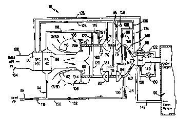
As best seen in FIG. 1, a preferred embodiment of the
integrated environmental control system 10 of the present
invention includes a first shaft means for mechanically
compressing and cooling a supply air such as first shaft 70
having mechanically secured thereto as mechanical
components a first fan 72, a first compressor 74, and a
first turbine 76; a second shaft means for mechanically
compressing and cooling a supply air, such as second shaft
78 having mechanically secured thereto as mechanical
components a second fan 80, a second compressor 82, and a
second tur~ine 84; common heat transfer component means for
cooling and controlling the humidity of a supply air
through heat exchange relationship with a cooling fluid
such as a common primary heat exchanger 86, a common
secondary heat exchanger 88, a common reheater 90, and a
CA 022~0060 1998-09-18
W097/37890 PCT~S97/0~740
-- 10 --
common condenser 92; a supply fluid delivery means for
delivering a supply air separately into mechanical
components of the first shaft means and the second shaft
meanC and for delivering the supply air in common through
S the common heat transfer component means to a load that
receives the conditioned air, such as supply fluid line 94;
and shutoff valve means for selectively shutting off
delivery of the supply air to either the first turbine 76
or second turbine 84 in the event of any interruption in
flow of coo}ed supply air flowing out of either the first
turbine 76 or second turbine 84, such as first shutoff
valve 96 and second shutoff valve 98, so that the supply
air continues to be conditioned by mechanical components of
the non-interrupted or surviving shaft means and by heat
transfer components of the common heat transfer component
means.
The integrated environmental control system 10 also
includes a ram air duct 100 housing the common primary and
secondary heat exchangers 86, 88. A receiving end 104 of
the ram air duct lOO receives ram air as a cooling fluid
from a source (not shown) outside of the integrated
environmental control system 10, such as ambient air
outside of an aircraft housing the system 10. A first fan
housing 106 of the ram air duct 100 receives the ram air
downstream of the common primary and secondary heat
exchangers 86, 88 and is structured to house the first fan
72 so that rotation of the first fan 72 by the first shaft
assists movement of the ram air through the ram air duct
lOO. Similarly, a second fan housing 108 houses the second
fan 80 downstream of the common primary and secondary heat
exchangers 86, 88 so that rotation of the second fan 80
assists movement of the ram air through the ram air duct
lOO. A first ram discharge check valve 110 is positioned
downstream of the first fan 72 within the first fan housing
106 so that no fluids or foreign objects are drawn into the
CA 022~0060 1998-09-18
W097/37890 PCT~S97/05740
first fan housing 106 in the event the first fan 72 is not
spinning while the second fan 80 i8 operating. A second
ram discharge check valve 112 is positioned downstream of
the second fan within the second fan housing 108 so that no
fluids or foreign objects are drawn into the second fan
housing 108 in the event the second fan 80 is not spinning
while the first fan 72 is operating. The first and second
fan housings 106, 108 are structured to permit discharge
of the ram air passing through the ram air duct lOO out of
the integrated environmental control system 10, or
"overboard" of an aircraft housing the system lO, as
indicated by the common abbreviations "OVBD" shown in FIG.
1.
The supply fluid line 94 includes a supply inlet 114
that receives and introduces a supply air such as "Bleed
Air" (as shown in FIG. 1) into the integrated environmental
control system 10. Typically the supply air is hot,
compressed bleed air directed from the compressor stages or
a gas turbine engine (not shown) or an auxiliary power unit
(not shown) in a manner well known in the art. A main
supply valve 116 regulates flow of the supply air beyond
the supply inlet 114 and into a common primary heat
exchanger line 118, which directs the supply air into,
through, and out of the common primary heat exchanger 86
where the supply air passes in heat exchange relationship
with the ram cooling air. Next, the supply air is split
into a first compressor line 119 that directs a portion of
the supply air into, through and out of the first
compressor 74, and into a second compressor line 120 that
directs a remaining portion of the supply air into, through
and out of the second compressor 82, where the supply air
is compressed by the first and second compressors 74, 82 to
a desired pressure in a manner well known in the art.
First compressor line 119 includes a first compressor check
valve 121, and second compressor line 120 includes a second
CA 022~0060 1998-09-18
W097/37890 PCT/US97/05740
-- 12 --
compressor check valve 122 that prevent reverse flow of any
supply air through the first or second compressor 74, 82
when normal supply air flow through either compressor is
interrupted, such as when the first or second shut off
5 valves 96, 98 have shut off flow of the supply air to
either the first or second turbine 76, 84.
After being compressed, the supply air flows out of
the first and second compressor lines 119, 120 into a
common secondary heat exchanger line 124 that directs the
lO supply air into the common secondary heat exchanger 88,
where the supply air again passes in heat exchange
relationship with the ram air. The supply air next leaves
the common secondary heat exchanger 88 in a reheater feed
line 126 that directs the supply air into and through the
15 common reheater 9O and common condenser 92, and into a
water collector feed line 128 that directs the supply air
into a water collector 130 (designated "W/C" for
convenience in FIG. 1). In the common condenser 92 the
supply air passes in heat exchange relationship with cooled
20 supply air discharged from the first and second turbines
76, 84 which causes a drop in temperature of the supply air
within the conunon condenser 92, thereby condensing moisture
within the supply air. The condensed moisture is removed
from the supply air in the water collector 130 in a manner
25 well ~cnown in the art. Next a secondary reheater injection
line 132 directs the supply air back into and through the
common reheater 9O wherein the supply air passes as a
secondary cooling fluid in heat exchange relationship with
the supply air passing through the common reheater 9O
30 within the reheater feed line 126. The supply air within
that reheater feed line 126 has not been cooled within the
common condenser 92, so it is at a higher tèmperature than
the supply air within the secondary reheater injection line
132. Consequently, the supply fluid in that secondary
35 reheater injection line 132 absorbs some of the heat from
CA 022~0060 l998-09-l8
W097/37890 PCT~S97/05740
- 13 -
the supply air in the reheater feed line 126, which causes
any entrained moisture in a vapor form within the supply
air to change to a gas phase prior to entering the first or
~econd turbines 76, 84, thereby minimizing moisture damage
to the turbines.
The supply air then moves out of the secondary
reheater injection line 132 into a reheater discharge line
134 where the supply air is again split so that a portion
flows into a first turbine feed line 136 that directs that
portion into the first turbine 76, while the remaining
portion of supply air passes into a second turbine feed
line 138 that directs that remaining portion into the
second turbine 84. Within the first and second turbines
76, 84 the separate portions of supply air are decompressed
and hence cooled, and simultaneously perform work on the
turbines 76, 84 causing the first turbine 76 to rotate the
first shaft 70 and the second turbine 84 to rotate the
second shaft 78 in a manner well known in the art. The
portion of supply air within the first turbine 76 passes
out of the first turbine within a first turbine discharge
line 140 and the remaining portion of the supply air within
the second turbine 84 passes out of the second turbine
within a second turbine discharge line 142.
The first and second turbine discharge lines 140, 142
direct the separate portions of supply air to mix together
again within a common condenser housing 144, where the
supply air serves as a tertiary cooling fluid for that
portion of the supply air in the reheater feed line 126
that is within the common condenser 92. The cooled supply
air then passes out of the common condenser housing 144 and
into a common cabin induction line 146 that directs the
then conditioned supply air into the aircraft cabin 56 (as
designated by the phrase "Cabin Supply" in FIG. 1).
A cabin recirculation line 148 directs supply air that
has been in the aircraft cabin 56 for a duration of time,
CA 022~0060 1998-09-18
W097/37890 PCT~S97/0~740
- 14 -
~n a well known manner (as designated by the phrase "Cabin
Return" in FIG. 1), from the cabin 56 to the common
condenser housing 144, in order to reduce some of the total
load requirements on the integrated environmental control
system 10, depending upon the varying aircraft pressure
requirements and ram air conditions, which are a function
of the aircraft's particular operating environment. For
example while boarding passengers or at low altitudes the
cabin pressurization requirements and ram air temperatures
differ markedly from the pressurization requirements and
ram air temperatures while at a cruise altitude of modern
aircraft. As is well known in the art, varying
recirculation of cabin air into the supply air delivered by
an environmental control system assists in lowering total
ram air requirements, etc.
A system bypass line 150 is in fluid communication
with the supply fluid line 94 between the main supply valve
116 and the common primary heat exchanger 86. The system
bypass line 150 directs a bypass portion of the supply air
through a bypass control valve 152 and then into a first
turbine bypass line 154 and a separate second turbine
bypass line 156. The first turbine bypass line 154 directs
some of the bypass portion of the supply air into the first
turbine discharge line 140, while the second turbine bypass
line 156 directs the remainder of the bypass portion of the
supply air into the second turbine discharge line 142. By
regulation of the bypass control valve 152 in a manner well
known in the art, variable amounts of the pressurized,
heated bleed air that serves as the supply air may be
injected directly downstream of the first and second
turbines 76, 84 to both melt any accumulated ice and also
to regulate the temperature of the supply air leaving the
turbines 76, 84.
The shutoff valve means for selectively shutting off
delivery of supply air to either the first turbine 76 or
CA 022~0060 l998-09-l8
W097/37890 PCT~S97/05740
- 15 -
the second turbine 84 includes detecting means for
detecting any interruption in the flow of cooled supply air
flowing out of either the first or second turbines 76, 84.
The detecting means is in electrical communication with
~oth a first shut off valve actuator 158 that controls the
first shut off valve 96 and a second shut off valve
actuator 160 that controls the second shut off valve 98,
and could comprise any of a variety of known detecting
mechanisms commonly used to monitor and isolate a failed
portion of an environmental control system, such as a first
compressor temperature monitor 162 that monitors
temperature changes of the supply air entering and leaving
the first compressor 74 and a second compressor temperature
monitor 164 that monitors temperature changes of the supply
air entering and leaving the second compressor 82.
In operation of the integrated environmental control
system lO of the present invention, because the mechanical
components (the first and second fan 72, 80, the first and
second compressor 74, 82, and the first and second turbine
76, 84) are mechanically secured to their respective first
or second shaft (meaning that rotation of the shaft rotates
moving parts of the mechanical components secured to the
shaft), failure of any one of the mechanical components
secured to either the first or second shaft 70, 78 will
necessarily effect mechanical performance of the compressor
secured to the shaft. For example, if the first turbine 76
starts to rotate below its desired level due to an ordinary
bearing deterioration within the turbine or for any reason,
the first shaft 70 will also slow its rotation which in
turn causes a slowing of the performance of the first
compressor 74, which will effect the temperatures of the
supply air leaving the first compressor 74. The first
compressor temperature monitor 162 of the detecting means
will sense the change from a desired temperature for the
first compressor 74, and will automatically actuate the
CA 022~0060 l998-09-l8
W097l37890 PCT~S97/05740
- 16 -
first shut off valve actuator 158 to shut off the first
shut off valve 96, thereby causing the supply air to stop
performing work on the first turbine 76 resulting in
cessation of rotation of the first shaft 70. In such a
circumstance, the integrated environmental control system
lO continues to supply conditioned air to the aircraft
cabin 56 in a redundant operating mode, wherein the supply
air continues to be conditioned by both the mechanical
components of the non-interrupted or surviving second shaft
means (including the second fan 80, second compressor 82
and second turbine 84), and also by the heat transfer
components (including the common primary and secondary heat
exchangers 86, 88, common reheater 9O, and common condenser
92 and water collector 130) of the common heat transfer
component means.
The common heat transfer component means must have
adequate heat transfer capacity to satisfy conditioned air
requirements of the specific load for which a particular
embodiment of the integrated environmental control system
is designed. Therefore, when the integrated
environmental control system 10 is operating in its
redundant operating mode utilizing the supply air
conditioning capabilities of only the mechanical components
of the surviving shaft means, the supply air is still
exposed to the total heat exchange capacity of the common
heat transfer component means. Consequently, the
integrated environmental control system 10 offers enhanced
performance in the redundant operating mode compared to
common non-integrated environmental control systems such as
the Two Pac~ ECS 12 shown in FIG. 2. Additionally, because
of that enhanced operating performance in the redundant
operating mode, the integrated environmental control system
will be able to satisfy minimum conditioned air
requirements of specific loads with mechanical components
that have a smaller performance capacity than the
CA 022~0060 1998-09-18
wos7/37890 PCT~S97/05740
- 17 -
mechanical components of known,non-integrated
environmental control systems.The integrated
environmental control system 10 also offers a redundant
operating mode frequency (being defined for purposes herein
S as the frequency of failure requiring operating of an
environmental control system in a redundant operating mode)
that is at least as low as known non-integrated
environmental control systems. That is because experience
in the art with known environmental control systems
demonstrates that failure is primarily associated with
mechanical components (e.g., fans, compressors, and/or
turbines) rather than heat transfer components, and the
integrated environmental control system 10 includes the
same potential redundancy in mechanical components as known
non-integrated environmental control systems, while
simplifying the heat transfer components and their related
housings and feed/discharge lines.
It is stressed that, while the integrated
environmental control system lO of the present invention
has been described with respect to a preferred and
particular embodiment, the system lO includes alternative
embodiments. In particular, the shaft means described
hereinabove may be modified for embodiments wherein no fan
is secured to the shaft so that each shaft means includes
only a compressor and turbine mechanically secured thereto,
and the ram air duct does not include specific fan
housin~s. Another structural modification for an
alternative embodiment is that more than two shaft means
are utilized with a single common heat transfer component
means. It will be understood by those skilled in the art,
that additional, obvious structural modifications can be
made without departing from the spirit of the invention.
Accordingly, reference should be made primarily to the
accompanying claims rather than the foregoing specification
to determine the scope of the invention. We Claim: