Note: Descriptions are shown in the official language in which they were submitted.
CA 02250185 1998-09-25
WO 97/36090 PCT/US97/04605
1
METHOD OF REGULATING DRILLING CONDITIONS
APPLIED TO A WELL BIT
' BACKGROUND OF THE INVENTION
The present invention pertains to the regulation, and preferably
optimization, of drilling conditions, specifically rotary speed and weight-on-
bit,
applied to a well bit. As used herein, the term "well bit" includes ordinary
well
drilling bits, as well as coring bits.
In the past, the regulation of such drilling conditions has often been more
a matter of art (or even guess work) than science.
To the present inventor's knowledge, there have been at least a few
efforts to take a more scientific approach to such regulation. For example,
U.S.
Patent No. 5,449,047 discloses "automatic" control of a drilling system. The
basic approach is simply to empirically maintain a given depth of cut (per
revolution) for a given range of rock compressive strengths.
"Best Constant Weight and Rotary Speed for Rotary Rock Bits," by E.M.
Galle and H.B. Woods, API Drillin4 and Production Practice, 1963, pages 48-73,
describes a method which operates on the assumption that, in any given
drilling
operation, if the weight-on-bit changes, the rotary speed will automatically
change accordingly (and/or vice-versa) such that the product of weight-on-bit
and rotary speed will remain constant throughout the drilling operation. (The
present inventors have found that, although a change in one of these variables
__ may cause a responsive change in the other, the assumption that the product
of the two always remains constant is invalid.) Proceeding on this assumption,
the method involves the use of laboratory tests to find weight-on-bit and
rotary
CA 02250185 1998-09-25
WO 97136090 PCT/LTS97/04605 -
2
speed combinations which-result in bit failure, and avoid those combinations.
Another technical paper, "Drilling Parameters and the Journal Bearing Bit," by
H. Word and M. Fisbeck, presented at the 34th Annual Petroleum Mechanical
Engineering Conference, Tulsa, Oklahoma, 1979, updates the last-mentioned
paper, but does not change the basic assumption and methodology.
None of the above methods optimize the overall drilling operation as well
as they might.
SUMMARY OF THE INVENTION
The present invention appears to provide a more universally valid
l0 criterion for avoiding at least catastrophic bit wear, and in preferred
embodiments of the invention, also avoiding unacceptably accelerated bit wear
rates, so that a balance may be achieved between bit life and other
parameters,
such as penetration rate. Although the drilling conditions ultimately
regulated
are preferably rotary speed and weight-on-bit, the aforementioned criterion is
neither one, the other, nor both of these parameters per se, but rather, is
power.
By using power as the basic criterion, it is possible, in preferred forms of
the
invention, to provide a selection of rotary speed and weight-on-bit
combinations
which will achieve the desired power, and then use still other criteria for
optimizing within this range.
In the most basic form of the present invention, the compressive strength
of the formation in an interval to be drilled by the bit is assayed. Critical
bit
_t structure of the same size and design as in the given bit, and which
structure
has drilled material of approximately the same compressive strength as that so
assayed, along with respective drilling data for the worn structure is
analyzed.
CA 02250185 1998-09-25
WO 97/36090 PCT/US97/04605
3
From this analysis, a power limit for the respective compressive strength is
determined. Above this power limit, undesirable bit wear is likely to occur.
In
very basic forms of the present invention, "undesirable" bit wear may be
chosen
to be catastrophic bit failure. However, in more highly preferred embodiments,
unduly accelerated wear rates are considered undesirable, and avoided by use
of the power limit.
In any case, this is done by regulating the drilling conditions at which the
given bit is operated to maintain a desired operating power less than or equal
to the power limit.
The "critical structure" so analyzed is defined as that structure which, in
the given bit design, will in all likelihood wear most rapidly andlor first
fail, so
that this structure is the limiting factor on bit life. For example, in
polycrystaiine
diamond compact ~"PDC") type drag bits, the cutters or polycrystaline diamond
compacts will usually be the critical structure. On the other hand, in roller
cone
type bits, the critical structure is typically the bearing or journal
structure.
in preferred embodiments of the invention, a plurality of such structures,
and their respective drilling data, are so analyzed. From those analyses, a
first
type series of correlated pairs of electrical signals are generated. The two
signals of each such pair correspond, respectively, to wear rate and operating
power for a respective one of the structures. The power limit is generated
from
these signals of the first type series. An advantage of analyzing multiple
critical
,_ structures and generating such a series of correlated pairs of signals is a
much
higher degree of certainty in determining a power limit above which
excessively
accelerated wear (as opposed to total failure) occurs. Thus, these preferred
CA 02250185 1998-09-25
WO 97/36090 PCT/US97/04605
4
embodiments can do more than simply avoid catastrophic bit wear, they can
balance a reasonable wear rate (and thus balance bit life) against other
factors
such as penetration rate.
"Corresponding," as used herein, with respect to signals or numerical
values, will mean "functionally related," and it will be understood that the
function in question could, but need not, be a simple equivalency
relationship.
"Corresponding precisely to," if used with respect to an electrical signal,
will
mean that the signal translates directly to the value of the very parameter in
question. "Wear rate" of a bit part may be defined either in units of length
l0 (measured from the outer profile of the new part) per unit time or volume
of
material (of the part) per unit time.
The drilling conditions regulated are preferably rotary speed and weight-
on-bit. in general, it is preferable to build in a safety factor, i.e. to
maintain the
power level somewhat less than the power limit, but about as close to the
limit
as reasonably possible. Thus, for example, "reasonably" includes the use of
the
aforementioned safety factor, as well as adjustment for various pragmatic
limitations on the drilling conditions to be regulated. By way of more
specific
example, a given rig may have a limit on rotary speed which does not permit
operation as close to the power limit as might, theoretically, be desired,
even
considering the safety factor. Likewise, in a hole which is not yet very deep,
it
may be a practical impossibility to apply enough weight-on-bit to operate as
__ close to the power limit as theoretically desirable.
Preferred embodiments of the invention further comprise generating a
second type series of correlated pairs of electrical signals, the respective
signals
CA 02250185 1998-09-25
WO 97/36090 PCTlUS97/04605
of each pair corresponding to a rotary speed value and a weight-on-bit value,
and wherein the rotary speed and weight-on-bit values of each pair
theoretically
result in a power corresponding to the power limit. In other words, even for a
constant rock strength and wear condition of the bit, there are a number of
5 different combinations of rotary speed and weight-on-bit which can
theoretically
result in a power at the aforementioned limit. The bit is preferably operated
at
a rotary speed and weight-on-bit corresponding to one of the pairs of signals
in
this second series. Recalling that "corresponding to" means functionally
related
to, it should be understood that this will could mean that the bit may be
operated
l0 at rotary speed and weight-on-bit values slightly less than those
corresponding
precisely to one of the pairs of signals, whereby a safety factor is included,
e.g.
because some bit vibrations almost always occur.
It is also possible to determine a rotary speed limit for the power limit,
above which substantially disadvantageous bit movement characteristics, such
as peak axial and lateral vibrations and bit whirl, are likely to occur. Thus,
even
though operating above this speed limit may result in the desired power, it is
preferable to operate the bit below this rotary speed limit. Likewise, it is
possible
to determine a weight-on-bit limit for the power limit above which other types
of
highly disadvantageous bit movement characteristics, such as peak torsional
vibrations and so-called "stick slip" are likely to occur, and it is likewise
desirable
to operate the bit at a weight-on-bit below this latter limit.
In preferred embodiments, a marginal rotary speed for the power limit,
which marginal rotary speed is less than the aforementioned rotary speed
limit,
is determined, above which undesirable bit movement characteristics, such as
CA 02250185 1998-09-25
WO 97136090 PCT/US97/04605
6 T
increasing axial and lateral vibrations, are likely to occur. It is likewise
preferable to determine a marginal weight-on-bit for the power limit, less
than the
aforementioned weight-on-bit limit, above which other types of undesirable bit
movement characteristics, such as increasing torsional vibrations, are likely
to
occur. Clearly, it will be even more preferable to operate the bit at a rotary
speed less than or equal to the marginal rotary speed, and at a weight-on-bit
less than or equal to the marginal weight-on-bit.
It is even further preferable to operate about as close as possible to an
optimum rotary speed and weight-on-bit combination as close as reasonably
possible to the marginal weight-on-bit.
It is also preferable to generate a plurality of such second series of
signals, each series corresponding to a different degree of bit wear, but for
the
same rock strength. Then, by modeling or monitoring bit wear and using these
other second type series, it is preferable to increase the weight-on-bit and
correspondingly alter the rotary speed as the bit wears. Likewise, it will
often be anticipated that the bit in question will be drilling through a
plurality of
formation layers or strata of different compressive strengths. In such
instances,
it is preferable to generate respective such first and second type series of
signals for each such compressive strength, monitor the progress of the bit
through the formation, and periodically alter the operation of the bit in
accord
with the respective series of signals for the compressive strength of the
formation currently being drilled by the bit.
Further details of the present invention and ways of implementing it, along
with various salient features, objects and advantages thereof, will be made
CA 02250185 1998-09-25
WO 97/36090 PCT/US97/04605 -
7
apparent by the following detailed description, along with the drawings and
claims.
BRIEF DESCRIPTION OF THE DRAWINGS
Fig. 1 is a diagrammatic illustration of drilling operations from which input
data can be generated and to which the invention can be applied, as related to
a computer.
Fig. 2 is a graphic illustration of power limits.
Fig. 3 is a graphic illustration of second type signal series for relatively
soft rock.
l0 Fig. 4 is a graphic illustration similar to that of Fig. 3, but for
relatively
hard rock.
Fig. 5 is a diagram generally illustrating a wear modeling process which
can be used in the present invention.
Fig. 6 is a graphic illustration of the rated work relationship.
Fig. 7 is a graphic illustration of work loss due to formation abrasivity.
DETAILED DESCRIPTION
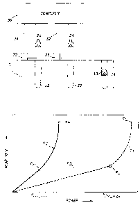
Fig. 1 illustrates an earth formation 10. It is intended that a given well bit
18 drill an interval 14 of the formation 10 generally corresponding to bore
hole
intervals 20 and 22, which have been drilled by bits 24 and 26, of the same
size
and design as bit 18.
t Before bit 18 is even started into its respective hole (as shown), the
compressive strength of the formation interval desired to be drilled by bit 18
will
have been assayed. This can conveniently be done, in a manner known in the
CA 02250185 1998-09-25
WO 97/36090 PCT/US97/04605
8 -
art, by analyzing drilling data, s~rch as well logs, discharged cuttings
analyses,
and core analyses, diagrammatically indicated at 28 and 30, from the nearby
hole intervals 20 and 22. For this part of the description, we will assume a
very
simple case in which the assay indicates a constant compressive strength over
the entire interval 14.
Next, a power limit is generated. Referring to Fig. 2, the present
inventors' research has shown that, as operating power is increased, the wear
rate of any given bit tends to follow a fairly predictable pattern. Curve c,
illustrates this pattern for a relatively soft rock, i.e. a rock of relatively
low
l0 compressive strength. It can be seen that the wear rate increases
approximately
linearly with increases in power up to a point p~. With further increases in
power, the wear rate begins to increase more rapidly, more specifically,
exponentially. These severe wear rates are due to increasing frictional
forces,
elevated temperature, and increasing vibration intensity (impulse loading).
Finally, the wear rate reaches an end point e~, which represents catastrophic
bit
failure. This catastrophic wear would occur at the power at this end point
under
steady state conditions in actual field drilling, but could occur at a lower
power,
i.e. somewhere between p~ and e~, under high impact loading due to excessive
vibrations. The curve c2 is a similar curve for a rock of relatively high
compressive strength. Again, the wear rate increases approximately linearly
with increase in power (albeit at a greater rate as indicated by the slope of
the
_t curve c2, up to a point pH, after which the wear rate begins to increase
more
rapidly until catastrophic failure is reached at point eH.
In order to generate an appropriate power limit, critical structure of the
CA 02250185 1998-09-25
WO 97/36090 PCT/US97/04605 -
9
same type as in the bit 18 is ar5alyzed. In less preferred embodiments of the
invention, such analysis could, for example, consists of running a single
polycrystaline diamond compact, mounted on a suitable support, against
material of approximately the same compressive strength as that assayed for
formation interval 14, in a laboratory, gradually increasing the operating
power,
until failure is observed. However, this failure could be anomalous, e.g. a
function of some peculiarity of the particular cutter so analyzed, and in any
event, would only give a power value for catastrophic failure, such as at
point eH
or e~. In the present invention, it is preferable to avoid not only such
to catastrophic failure, but also to avoid operating at power levels which
produce
the exponentially increasing wear rates exemplified by the portions of the
curves
between points pH and eH, and between points p~ and e~.
Therefore, in the preferred embodiments, a plurality of critical structures
of the same size and design as in bit 18, and which structures have drilled
material of approximately the same compressive strength as that so assayed,
along with respective drilling data are analyzed. Some of these structures may
be separate bit parts or subassemblies, especially if the bit 18 is of the PDC
drag type wherein the critical structures are the cutters, worn and analyzed
under laboratory conditions. However, it is helpful if at least some of the
structures so analyzed be incorporated in complete bits which are worn in
field
drilling. For example, these could include bits 24 and 26 from holes 20 and
22,
f which would be analyzed along with their respective drilling data 32 and 34.
These latter bits and respective drilling data may also provide data for
further
aspects of the invention, to be described below.
CA 02250185 1998-09-25
WO 97/36090 PCT/L1S97/04605
In any event, from the data from the critical structures so analyzed,
corresponding electrical signals are generated and processed in a computer 36
to generate a first type series of correlated pairs of electrical signals.
Before elaborating on this first type series of correlated pairs of electrical
5 signals, it is noted that, for the sake of simplicity and clarity of Fig. 1,
only two
worn bits and their respective holes and drilling data are illustrated.
However,
in preferred embodiments, the first type series of signals would be generated
from a greater number of worn bits and their respective drilling data. These
could come from the same formation 10 or from other fields having formations
10 of comparable compressive strengths and/or multiple lab tests.
In the first type series of correlated pairs of electrical signals, the two
signals of each such pair correspond, respectively, to wear rate and operating
power for the respective worn bit.
Fig. 2 is a mathematical, specifically graphical, illustration of the
I S relationships between these signals. The curve c, represents the
aforementioned series of the first type for rock of a relatively low
compressive
strength. By processing the series of signals corresponding to the curve c,,
it
is possible for computer 36 to generate an electrical power limit signal
corresponding to a power limit, e.g. the power value at point p~, for the low
compressive strength in question, above which power limit excessive wear is
likely to occur.
-- A second series of correlated pairs of signals of the first type is
likewise
generated for a relatively high compressive strength, and a graphic
illustration
of the relationship between these signals is illustrated by curve cz. Again,
from
CA 02250185 1998-09-25
WO 97/36090 PCTlUS97/04605
these signals, an electrical power limit signal can be generated, which signal
corresponds to a power limit at critical point pH, where wear rate stops
increasing
linearly with increase in power, and begins to increase exponentially.
In accord with preferred embodiments of the present invention, additional
series of the first type, comprising correlated pairs of signals, would be
generated for intermediate compressive strengths. From the signals of each
such series, a power limit signal for the respective compressive strength
would
be generated. These other series are not graphically illustrated in Fig. 2,
for
simplicity and clarity of the illustration. It would be seen that, if they
were
illustrated, points such as p~ and pH chosen as the power limits, and the
power
limit points of all curves connected, the connections would result in the
curve c3,
which would give power limits for virtually all compressive strengths in a
desired
range. It will be appreciated that computer 36 can be made to process the
signals in these various series to result in another type of series of signals
corresponding to curve c.3. Assuming the curve c, is for the lowest
compressive
strength in the desired range, and the curve c2 for the highest, then the
values
pa,".",;~ and p,;",~,~ represent the power limits of a range of feasible
powers for the
bit design in question. It is noted that the curve c3 could theoretically be
viewed
as also a function of cutter (or tooth) metallurgy and diamond quality, but
these
factors are negligible, as a practical matter.
A most basic aspect of the present invention includes regulating drilling
conditions at which the given bit 18 is operated to maintain a desired
operating
power level less than or equal to the power limit for the compressive strength
assayed for the rock currently being drilled by that bit. Preferably, the
power
CA 02250185 1998-09-25
WO 97/36090 PCT/US97/04605
12
limit chosen is a point such ~as P~, where wear rate begins to increase
exponentially. However, in less preferred embodiments, it could be higher.
Thus, when drilling through the softest rock in the range, the conditions are
regulated to keep the power at or below the power p~;m-m~. Preferably, the
power
is kept less than the power limit, to provide a safety factor. However, it is
desirable that the power be maintained about as close as reasonably possible
to the power limit. "As close as reasonably possible" is meant to allow for
not
only the aforementioned safety factor, but also for practical limitations,
e.g.
limitations of the drilling rig being used such as torque limit, flow rate
limit, etc.
This expression is modified by "about" because the spirit of this aspect of
preferred forms of the invention is meant to include workable variations, the
maximum values of which may vary, e.g. with cost of operating time or a given
operator's assessment of an appropriate safety factor.
Operating as close as reasonably possible to the power limit maximizes
the rate of penetration, which is directly proportional to power. In general,
it is
desirable to maximize penetration rate, except in extreme cases wherein one
might begin drilling so fast that the quantity of cuttings generated would
increase
the effective mud weight to the point where it could exceed the fracture
gradient
for the formation.
The drilling conditions so regulated include conditions applied to the bit,
specifically rotary speed and weight-on-bit. Bit vibrations, which can be
_y detected while drilling through known means, may cause the forces
transmitted
to the formation by the bit to vary over small increments of the interval
being
drilled or to be drilled. In such instances, it is preferable that the applied
CA 02250185 1998-09-25
WO 97136090 PCT/US97/04605
13 -
conditions be regulated with reference to the peak transmitted forces among
these fluctuations, rather than, say, the mean transmitted forces.
In accord with another aspect of preferred forms of the invention, there
are a number of combinations of rotary speed and weight-on-bit, any one of
which will result in a power corresponding to the power limit. The invention
includes a method of optimizing the particular combination chosen.
Fig. 3 includes a curve c4 representing values corresponding to paired
signals in a series of a second type for a new bit of the design in question.
The
signal series corresponding to curve c4 is generated, in a manner described
more fully below, from historical data from a number of bits of the same size
and
design as bit 18, and which have drilled formation of approximately the same
compressive strength as that assayed for the interval 14. A curve such as c4
may result from plotting the rotary speed values against the weight-on-bit
values
from the individual historical data and then extrapolating a continuous curve.
It
will be appreciated that those of skill in the art could program computer 36
to
perform equivalent operations on correlated pairs of electrical signals
corresponding, respectively, to the rotary speed and weight-on-bit values of
the
historical data, and that the computer 36 could even produce a graphical
representation such as curve c4. The historical data would be used to generate
corresponding electrical signals inputted into the computer 36, which then
further generates sufficient additional such pairs of signals, consistent with
the
__ pattern from the original inputs, to provide a second type series of
correlated
pairs of weight-on-bit and rotary speed signals. From this second series, the
graphical representation c4 can be extrapolated, indeed generated by computer
CA 02250185 1998-09-25
WO 97/36090 PCTlUS97/04605
14
36. -
Correlating the curve c4 (andlor the corresponding series of signals) with
the historical drilling data (or corresponding signals), it is possible to
determine
a point pN_",e~ at which the rotary speed value, N, is at a marginal desirable
value,
i.e. a value above which undesirable bit movement characteristics are likely
to
occur, specifically the inevitable lateral and/or axial vibrations begin to
increase,
either because the rotary speed is too high andlor the corresponding weight-on-
bit is too low. At another point pN_,;m, at which the rotary speed is even
higher,
these undesirable bit movement characteristics, specifically axial and/or
lateral
l0 vibrations, peak, e.g. resulting in bit whirl; thus it is even less
desirable to
operate near or above the rotary speed at p,,,.,;m. The weight-on-bit at pN-
;;m is the
minimum weight-on-bit needed to dampen such vibrations and is sometimes
referred to herein as the "threshold" weight-on-bit.
Likewise, it is possible to locate a point p",-mar at which the weight-on-bit,
w, is at a marginal desirable value in that, above this value, other kinds of
undesirable bit movement characteristics, specifically increasing torsional
vibrations, occur. At pW-,;m these undesirable movements peak and "stick-slip"
{jerky rather than continuous bit rotation) may occur, so it is even less
desirable
to operate with weights near or above the weight-on-bit value at pW-,;m.
in general, although any point on the curve c4 includes a rotary speed and
weight-on-bit value corresponding to the power limit for the compressive
a strength in question and for a new bit, it will clearly be desirable to
operate
within the range between points pN_mar and pW_mar. As illustrated, the curve
c4
corresponds precisely to the power limit. Therefore, to include the
CA 02250185 1998-09-25
WO 97/36090 PCT/US97/04605
15 -
aforementioned safety feaiure,wit would be even more preferable to operate in
a range short of either of the points pN.~,ar or Pw_mar~ Even more preferably,
one
should operate at values corresponding to a point on the curve c4 at which the
weight-on-bit value, w, is less than, but about as close as reasonably
possible
to the weight-on-bit value at p",~~. This is because, the higher the rotary
speed,
the more energy is available for potential vibration of the drill string (as
opposed
to just the bit per se).
Bearing in mind that Fig. 3 pertains to relatively soft rock, it will be seen
that, about as close as reasonably possible to p,N,",a~ will, in this case,
actually be
rather far from pW,"a~. This is because, in very soft rock, the bit will reach
a
maximum depth of cut, wherein the cutting structures of the bit are fully
embedded in the rock, at a weight-on-bit value at point pd~, which is well
below
the weight~n-bit value at p",~r For PDC and roller cone bits, it is
unreasonable,
and useless, to apply additional weight on the bit beyond that which fully
embeds the cutters. For diamond impregnated bits, it may be desirable to
operate at a weight-on-bit somewhat greater than that at pd~. This partially
embeds the matrix bit body, into which the diamonds are impregnated. Thus the
matrix wears along with the diamonds so that the diamonds always protrude
somewhat from the matrix (a condition sometimes called "self-sharpening").
2o Therefore, the optimum rotary speed and weight-on-bit values will be those
at
or near point pd~.
From additional historical drilling data, another series of correlated
signals of the second type can be generated for a badly worn bit of the type
in
question, and these correspond to the curve cs. Intermediate series of this
CA 02250185 1998-09-25
WO 97/36090 PCT/US97/04605
16
second type, for lesser degrees of wear, could also be generated, but are not
illustrated by curves in Fig. 3 for simplicity and clarity of illustration. In
any
event, the computer 36 can be made to process the signals of these various
series, in a manner well known in the art, so as to generate series of signals
of
a third type corresponding to curves cs, c,, cg, cs, and coo . Curve cs
corresponds
to p,,,..,;m type values, as they vary with wear. Curve c-, corresponds to
pN_ma~ type
values as they vary with bit wear. Curve c$ corresponds to pd~ type values as
they vary with bit wear. Curve c9 corresponds to pW_ma, type values as they
vary
with bit wear. And curve c,o corresponds to pW_;;m type values as they vary
with
wear. Thus, as drilling proceeds, it is desirable to measure and/or model the
wear of bit 18, and periodically increase the weight-on-bit, and
correspondingly
alter the rotary speed, preferably staying within the range between curves cs
and
c,o, more preferably between curve c, and curve cs, and even more preferably
at or near curve ce.
Fig. 4 is similar to Fig. 3, but represents series of signals for a relatively
hard {high compressive strength) rock. Here, again, there are shown two curves
c" and c,z corresponding, respectively, to series of signals of the second
type
for a new and badly worn bit. In this hard rock, the point pW_ma~ whereafter
further
increases in weight-on-bit will result in undesirable torsional vibrations,
has a
weight-on-bit value less than that of point p~ and so, therefore does p",_;;m.
Thus,
in hard rock, even allowing for a safety factor, it will be possible to
operate at an
optimum pair of values, occurring at pops much closer to pW_m8~, than is the
case
for soft rock. Other pairs of values, analogous to pops, can be found for
varying
degrees of bit wear. From the signals corresponding to these, a series of
paired
CA 02250185 1998-09-25
WO 97/36090 PCT/US97/04605
17
electrical signals can be generated and corresponding curve c,3 extrapolated
by
computer 36.
As before, "as close as reasonably possible" is meant to allow for not only
a safety factor, but also for practical limitations. For example, a
theoretically
optimum pair of rotary speed, weight-on-bit values might, in the context of a
particular drill string geometry or hole geometry, produce drill string
resonance,
which should be avoided.
In other highly unusual examples, the rock may be so hard, and the
torque capability of the motor so low, that the rig is incapable of applying
enough
l0 weight-on-bit to even reach the threshold weight-on-bit value at pN_;;m.
Then it
is impossible to even stay within the range between pN_,;m and pW_,;m. Then
one
would operate about as close as reasonably possible to this range, e.g. at a
weight-on-bit less than that at pN_,;m and a correspondingly high rotary
speed.
It should also be borne in mind that, while values such as those shown
on the various curves in Figs. 3 and 4 are generally valid, aberrant
conditions
in a particular drilling operation may cause undesirable bit and/or drill
string
movements at rotary speed and weight-on-bit values at which they should not,
theoretically, occur. Thus it is desirable to provide means, known in the art,
to
detect such movements in real time (while drilling) and take appropriate
corrective action whenever such movements are detected, staying as close to
the optimum values as possible while still correcting the condition.
t With the above general concepts in mind, there will now be described one
exemplary method of processing signals to obtain series of signals of the type
corresponding to the curves in Figs. 3 and 4.
CA 02250185 1998-09-25
WO 97/36090 PCT/US97/04605 --
18
For the rock strength Q in question, historical empirical wear and power
data are used to generate corresponding electrical signals, and those signals
are processed by computer 36 to generate a series of paired signals of the
first
type, corresponding to a limiting power curve such as c, or cz.
Next, from historical empirical data, e.g. logs from holes 20 and 22
showing torque and vibration measurements, limiting torque values may be
determined. Specifically a torque value T,,,..,;," at which lateral and axial
vibrations
peak, i.e. a value corresponding pN_~;," for the o and wear condition in
question,
and a torque value T,~,.,;m at which torsional vibrations peak (produce "stick
slip"),
i.e. a value corresponding to pW_;;m for the v and the wear condition in
question,
are determined. Preferably, torque values TN.mar and TW_mar corresponding,
respectively, to pN_rtar and pW.mar for the a and wear condition in question
are
likewise determined.
Preferably, there are plentiful torque and vibration data for the o and wear
condition in question. These are converted to corresponding electrical signals
inputted into computer 36. These signals are processed by computer 36 to
produce signals corresponding to the torque values TN_,;m, TN-mar, TW.mat and
TW_,;m.
At least if a is low, i.e. the rock is soft, and preferably in any case, a
torque value Td~, corresponding to the torque at which the maximum depth of
cut
is reached (i.e. the cutting structure is fully embedded) is also determined.
It will
f be seen that this value and its corresponding electrical signal also
correspond
to pd~.
The data for determining Td~ can be provided by laboratory tests.
CA 02250185 1998-09-25
WO 97/36090 PCT/US97/04605
19
Alternatively, in an actual drilling operation in the field, Td~ can be
determined
by beginning to drill at a fixed rotary speed and minimal weight-on-bit, then
gradually increasing the weight-on-bit while monitoring torque and penetration
rate. Penetration rate will increase with weight-on-bit to a point at which it
will
level off, or even drop. The torque at that point is Td~.
For each of the aforementioned torque values, it is possible to
process the corresponding electrical signal to produce signals corresponding
to
corresponding rotary speed and weight-on-bit values, and thus to locate a
corresponding point on a curve such as those shown in Figs. 3 and 4.
to A value w, the weight-on-bit corresponding to the torque, T, in question
can be determined and a corresponding signal generated and inputted into
computer 36.
Alternatively, where signal series or families of series are being
developed to provide complete advance guidelines for a particular bit, it may
be
helpful to define, from field data, a value, N, which varies with wear:
TT
°
w w°
where To = torque for threshold weight-on-bit
wo = threshold weight-on-bit
Then computer 36 processes the T, To, wo and N signals to perform the
2~0 electronic equivalent of solving the equation:
T-T°
w . , w°
N
CA 02250185 1998-09-25
WO 97/36090 PCT/LTS97/04605
to produce a signal corresponding to the weight-on-bit corresponding to the
torque in question.
Next, computer 36 performs the electronic equivalent of solving the
equation:
N - P~I(2a ~ . d~ )w60
5 (3)
or
d
N - P~l(2a.-)T60
(3a)
where N = rotary speed
P,;m = the power limit previously determined as
10 described above
d~ = penetration per revolution (or "depth of cut")
where it is desired to use both axial and torsional components (the lateral
component being negligible). Alternatively, if it is desired to use the
torsional
component only, these equations become:
1 S N = Pnm ~ 1201ILJw (4)
or
N = P,;m~120n T (4a)
The computer does this by processing signals corresponding to the variables
and constants in equation (3), (3a), (4) or (4a).
20 We now have signals corresponding, respectively, to a weight-on-bit, w,
CA 02250185 1998-09-25
WO 97/36090 PCT/US97/04605
21
and a rotary speed, N, corresponding to the torque, T, in question, i.e. a
first pair
of signals for a series of the second type represented by curves c4, c5, c",
and
c,2. For example, if the torque used was TN.~im, we can locate point PN_,;m.
By similarly processing additional torque signals for the same bit wear
condition and rock strength, a, we can develop the entire second type series
of
pairs, corresponding to a curve such as c4, including all the reference points
pN_
~im~ pN.man pdc~ pw-mar and pw_;;m.
Then, when drilling with a bit of the size, design and wear condition in
question, in rock of the strength a in question, one operates at a rotary
speed,
weight-on-bit combination corresponding to a pair of signals in this series,
in the
range between pN_~;m and pw_,;m, unless w at pw_,;m > w at pd~, in which case
one
operates at values between pN~;m and pd~.
More preferably, one operates between PN_mar and pw_",a~, or p,~_mer and pd~,
whichever gives the smaller range. Even more preferably one operates about
as close as reasonably possible to p~ or pw.mar, whichever has the lower
weight-
on-bit. If p~ has the lower weight-on-bit, and the bit is of the PDC or roller
cone
type, one operates at or slightly below the values at per, depending on the
safety
factor desired. However, if the bit is of the diamond impreg type, one might
prefer to operate at or slightly above pd~.
By similar processing of signals for the same rock strength, a, but
different wear conditions, one can develop a family of series of paired
signals
__ of the second type, which can be depicted as a family of curves or a
region,
such as the region between curves c" and c,2.
It is then possible to develop series of the third type, corresponding, for
CA 02250185 1998-09-25
WO 97/36090 PCTlUS97/04605
22
example, to curves cg and c,3. Then, by monitoring or modeling the wear of the
bit, one can optimize by increasing the weight-on-bit, w, applied as the bit
wears
and correspondingly adjusting the rotary speed, N.
In less preferred embodiments, one may simply select a torque ToPt, e.g.
as close as reasonably possible to Td~ or TW_mar, whichever is less, then
process
as explained above to obtain the corresponding w and N. Repeating this for
different wear conditions, one can simply generate a series of the third type,
e.g.
corresponding to curve c,3.
However, it is preferable to develop ranges, as shown in Figs. 3 and 4 to
provide guidelines for modification of the hypothetical optimum operating
conditions. For example, if operating at poet with a particular string and
hole
geometry should produce resonance in the string, the operator can then select
another set of conditions between pN-mar and pw-mar
It will be understood by those of skill in the art that many alternate ways
of generating and processing data to generate the signal series are possible,
the
above being exemplary.
As mentioned above, up to this point, we have assumed a is constant
over interval 14. However, in actual drilling operations, v may vary over the
interval drilled by one bit. Thus, regardless of the method used to develop
signal series of the second and third type for a given rock strength, it is
desirable
to repeat the above process for other rock strengths which the bit in question
is
designed to drill. For example, for a given bit, one might develop signal
series
corresponding to curves such as shown in Fig. 3 for the softest rock it is
anticipated the bit will drill, other signal series corresponding to curves
such as
CA 02250185 2005-02-09
WO A7/36090 > > PCT/US97/04605 -
23
shown in Fig. 4 for the hardest rock, and still other such series for
intermediate
rock strengths. This can provide an operator in the field with more complete
information on optimizing use of the bit in-question.
Then, for example, if the assay of the-interval-to be drilled by the bit
includes strata of different rock strengths, the operation in each of these
strata
can be optimized. By way of further example, if the assay is based on adjacent
holes, but MWD measurements indicate that rock of a different strength is, for
some reason, being encountered in the hole in question, the operating
conditions can be changed accordingly.
l0 In even more highly preferred embodiments, it is possible to model a in
real time, as it changes with relatively small increases in depth, as
explained in
the present inventors' Canadian Application No. 2,250,090, entitled
"Method of Assaying Compressive Strength of Rock", filed on March 21,
'1997 end published ors -October 2, 1997.
As previously mentioned, in order to take best advantage of the present
invention, it is advisable to model the wear of the bit as it proceeds through
the
interval it drills, or, given available technology, measure the wear of the
bit or
some parameter indicative thereof in real time, so that the weight-on-bit and
rotary speed can be periodically adjusted to new optima for the current wear
condition of the bit.
Some prior U.S. patents, such as No. 3,058,532, No. 2,560,328, No.
2,580,860, No. 4,785,895, No. 4,785,894, No. 4,655,300, No. 3,853,184, No.
3,363,702, and No. 2,925,251, disclose various technologies purporting to
directly detect bit wear in real time.
CA 02250185 1998-09-25
WO 97/36090 PCT/US97/04605
24
Prior U.S. Patent No. 5,3175,836 to Holbrook discloses a technique for
modeling bit wear in real time.
Another method of modeling bit wear is as follows:
Referring to Fig. 5, the wear modeling proceeds from assaying work of a
well drilling bit such as 24 of the same size and design as bit 18. As in Fig.
1,
a well bore or hole section 20 is drilled, at feast partially with the bit 24.
More
specifically, bit 24 will have drilled the hole 20 between an initial point I
and a
terminal point T. In this illustrative embodiment, the initial point I is the
point at
which the bit 24 was first put to work in the hole 20, and the terminal point
T is
the point at which the bit 24 was withdrawn. However, for purposes of assaying
work per se, points I and T can be any two points which can be identified,
between which the bit 24 has drilled, and between which the necessary data, to
be described below, can be generated.
The basic rationale is to assay the work by using the well known
relationship:
b FcD C5)
where:
~2b = bit work
Fb = total force at the bit
D = distance drilled
The length of the interval of the hole 20 between points I and T can be
determined and recorded as one of a number of well data which can be
generated upon drilling the hole 20, as diagrammatically indicated by the line
50.
To convert it into an appropriate form for inputting into and processing by
the
CA 02250185 1998-09-25
WO 97/36090 PCT/US97/04605
computer 36, this length, i.e. distance between points I and T, is preferably
subdivided into a number of small increments of distance, e.g. of about one-
half
foot each. For each of these incremental distance values, a corresponding
electrical incremental distance signal is generated and inputted into the
5 computer 36, as indicated by line 52.
In order to determine the work, a plurality of electrical incremental actual
force signals, each corresponding to the force of the bit over a respective
increment of the distance between points I and T, are also generated. However,
because of the difficulties inherent in directly determining the total bit
force,
10 signals corresponding to other parameters from the well data 50, for each
increment of the distance, are inputted, as indicated at 52. These can,
theoretically, be capable of determining the true total bit force, which
includes
the applied axial force, the torsional force, and any applied lateral force.
However, unless lateral force is purposely applied (in which case it is
known),
15 i.e, unless stabilizers are absent from the bottom hole assembly, the
lateral force
is so negligible that it can be ignored.
In one embodiment, the well data used to generate the incremental actual
force signals are:
- weight on bit (w), e.g. in Ib.;
20 - hydraulic impact force of drilling fluid (F;), e.g. in Ib.;
- rotary speed, in rpm (N);
- - torque (T), e.g. in ft.*Ib.;
- penetration rate (R), e.g. in ft./hr. and;
- lateral force, if applicable (F,), e.g. in Ib.
CA 02250185 1998-09-25
WO 97/36090 PCT/US97/04605
26
With these data for each increment, respectively, converted to
corresponding signals and inputted as indicated at 52, the computer 36 is
programmed or configured to process those signals to generate the incremental
actual force signals by performing the electronic equivalent of solving the
following equation:
f2b = [(w + F;) + 120nNTIR + F,]D (6)
where the lateral force, F,, is negligible, that term, and the corresponding
electrical signal, drop out.
Surprisingly, it has been found that the torsional component of the force
is the most dominant and important, and in less preferred embodiments of the
invention, the work assay may be performed using this component of force
alone, in which case the corresponding equation becomes:
~2b = [120nNT/RJD
In an alternate embodiment, in generating the incremental actual force
signals, the computer 36 may use the electronic equivalent of the equation:
~b = 2rrTD/d~ (g)
where d represents depth of cut per revolution, and is, in turn, defined by
the relationship:
d~ = R/60N (g)
The computer 36 is programmed or configured to then process the
incremental actual force signals and the respective incremental distance
signals
x to produce an electrical signal corresponding to the total work done by the
bit
24 in drilling between the points I and T, as indicated at block 54. This
signal
may be readily converted to a humanly perceivable numerical value outputted
CA 02250185 1998-09-25
WO 97/36090 PCT/US97/04605
27
by computer 36, as indicated by the line 56, in the well known manner.
The processing of the incremental actual force signals and incremental
distance signals to produce total work 54 may be done in several different
ways.
For example:
In one version, the computer processes the incremental actual force
signals and the incremental distance signals to produce an electrical weighted
average force signal corresponding to a weighted average of the force exerted
by the bit between the initial and terminal points. By "weighted average" is
meant that each force value corresponding to one or more of the incremental
l0 actual force signals is 'weighted" by the number of distance increments at
which
that force applied. Then, the computer simply performs the electronic
equivalent
of multiplying the weighted average force by the total distance between points
I and T to produce a signal corresponding to the total work value.
In another version, the respective incremental actual force signal and
incremental distance signal for each increment are processed to produce a
respective electrical incremental actual work signal, whereafter these
incremental actual work signals are cumulated to produce an electrical total
work
signal corresponding to the total work value.
In still another version, the computer may develop a force versus distance
function from the incremental actual force signals and incremental distance
signals, and then perForm the electronic equivalent of integrating that
function.
-- Not only are the three ways of processing the signals to produce a total
work signal equivalent, they are also exemplary of the kinds of alternative
processes which will be considered equivalents in connection with other
CA 02250185 1998-09-25
WO 97/36090 PCTILTS97/04605
28
processes forming various parts of the present invention, and described below.
Technology is now available for determining when a bit is vibrating
excessively while drilling. If it is determined that this has occurred over at
least
a portion of the interval between points I and T, then it may be preferable to
suitably program and input computer 36 so as to produce respective incremental
actual force signals for the increments in question, each of which corresponds
to the average bit force for the respective increment. This may be done by
using
the average (mean) value for each of the variables which go into the
determination of the incremental actual force signal.
to Wear of a drill bit is functionally related to the cumulative work done by
the bit. In addition to determining the work done by bit 24 in drilling
between
points I and T, the wear of the bit 24 in drilling that interval is measured.
A
corresponding electrical signal is generated and inputted into the computer as
part of the historical data 58, 52. (Thus, for this purpose, point I should be
the
point the bit 24 is first put to work in the hole 20, and point T should be
the point
at which bit 24 is removed.) The same may be done for additional holes 22 and
60, and their respective bits 26 and 62.
Figure 6 is a graphic representation of what the computer 36 can do,
electronically, with the signals corresponding to such data. Figure 6
represents
a graph of bit wear versus work. Using the aforementioned data, the computer
36 can process the corresponding signals to correlate respective work and wear
-t signals and pertorm the electronic equivalent of locating a point on this
graph
for each of the holes 20, 22 and 60, and its respective bit. For example,
point
24' may represent the correlated work and wear for the bit 24, point 26' may
CA 02250185 1998-09-25
WO 97/36090 PCT/US97/04605
29
represent the correlated work 'and wear for the bit 26, and point 62' may
represent the correlated work and wear for the bit 62. Other points p,, p2 and
p3
represent the work and wear for still other bits of the same design and size
not
shown in Figure 5.
By processing the signals corresponding to these points, the computer
36 can generate a function, defined by suitable electrical signals, which
function,
when graphically represented, takes the form of a smooth curve generally of
the
form of curve c.~ it will be appreciated, that in the interest of generating a
smooth
and continuous curve, such curve may not pass precisely through all of the
individual points corresponding to specific empirical data. This continuous
"rated work relationship" can be an output 64 in its own right, and can also
be
used in the wear modeling.
It is helpful to determine an end point p"~,~ which represents the maximum
bit wear which can be endured before the bit is no longer realistically useful
and,
from the rated work relationship, determining the corresponding amount of
work.
Thus, the point pm~ represents a maximum-wear-maximum-work point,
sometimes referred to herein as the "work rating" of the type of bit in
question.
It may also be helpful to develop a relationship represented by the mirror
image
of curve cue, i.e. curve cue, which plots remaining useful bit life versus
work done
from the aforementioned signals.
The electrical signals in the computer which correspond to the functions
_a represented by the curves czo and cz2 are preferably transformed into a
visually
perceptible form, such as the curves as shown in Fig. 6, when outputted at 64.
As mentioned above in another context, bit vibrations may cause the bit
CA 02250185 1998-09-25
WO 97/36090 PCT/US97/04605
force to vary significantly over individual increments. In developing the
rated
work relationship, it is preferable in such cases, to generate a respective
peak
force signal corresponding to the maximum force of the bit over each such
increment. A limit corresponding to the maximum allowable force for the rock
5 strength of that increment can also be determined as explained below. For
any
such bit which is potentially considered for use in developing the curve c,, a
value corresponding to the peak force signal should be compared to the limit,
and if that value is greater than or equal to the limit, the respective bit
should be
excluded from those from which the rated work relationship signals are
1 o generated. This comparison can, of course, be done electronically by
computer
36, utilizing an electrical limit signal corresponding to the aforementioned
limit.
The rationale for determining the aforementioned limit is based on the
power limit explained above in connection with Fig. 2. Once the limiting power
for the appropriate rock strength is thus determined, the corresponding
15 maximum force limit may be extrapolated by simply dividing this power by
the
rate of penetration.
Alternatively, the actual bit power could be compared directly to the power
limit.
In either case, the process may be done electronically by computer 36.
20 Other factors can also affect the intensity of the vibrations, and these
may
also be taken into account in preferred embodiments. Such other factors
include
_,_ drill string geometry and rigidity, hole geometry, and the mass of the
bottom hole
assembly below the neutral point in the drill string.
The manner of generating the peak force signal may be the same as that
CA 02250185 1998-09-25
WO 97/36090 PCT/US97/04605
31
described above in generating incremental actual force signals for increments
in which there is no vibration problem, i.e. using the electronic equivalents
of
equations (5), (6), or (7)+(8), except that for each of the variables, e.g. w,
the
maximum or peak value of that variable for the interval in question will be
used
(but for R, for which the minimum value should be used).
The rated work relationship 66 may be used in developing information on
abrasivity, as indicated at 68. Abrasivity, in turn, can be used to enhance
the
wear modeling and/or to adjust the power limit. Specifically, if abrasivity is
detected, the power limit should be lowered for that section of the interval
being
drilled.
As for the abrasivity per se, it is necessary to have additional historical
data, more specifically abrasivity data 70, from an additional well or hole 72
which has been drilled through an abrasive stratum such as "hard stringer" 74,
and the bit 76 which drilled the interval including hard stringer 74.
It should be noted that, as used herein, a statement that a portion of the
formation is "abrasive" means that the rock in question is relatively
abrasive, e.g.
quartz or sandstone, by way of comparison to shale. Rock abrasivity is
essentially a function of the rock surface configuration and the rock
strength.
The configuration factor is not necessarily related to grain size, but rather
than
2o to grain angularity or "sharpness."
Turning again to Fig. 5, the abrasivity data 70 include the same type of
data 78 from the well 72 as data 50, i.e. those well data necessary to
determine
work, as well as a wear measurement 80 for the bit 76. In addition, the
abrasivity data include the volume 82 of abrasive medium 74 drilled by bit 78.
CA 02250185 1998-09-25
WO 97/36090 PCT/US97/04605
32
The latter can be determined in a known manner by analysis of well logs from
hole 72, as generally indicated by the black box 84.
As with other aspects of this invention, the data are converted into
respective electrical signals inputted into the computer 36 as indicated at
86.
The computer 16 quantifies abrasivity by processing the signals to perform the
electronic equivalent of solving the equation:
~ - (rated - ~b)Nabr 10)
where:
h = abrasivity
fib = actual bit work (for amount of wear of bit 56)
i2,9t~ = rated work (for the same amount of wear)
Vabr = volume of abrasive medium drilled
For instance, suppose that a bit has done 1,000 ton-miles of work and is
pulled with 50% wear after drilling 200 cubic feet of abrasive medium. Suppose
also that the historical rated work relationship for that particular bit
indicates that
the wear should be only 40% at 1,000 ton-miles and 50% at 1,200 ton-miles of
work as indicated in Fig. 7. In other words, the extra 10% of abrasive wear
corresponds to an additional 200 ton-miles of work. Abrasivity is quantified
as
a reduction in bit life of 200 ton-miles per 200 cubic feet of abrasive medium
drilled or 1 (ton*miie/ft3). This unit of measure is dimensionally equivalent
to
laboratory abrasivity tests. The volume percent of abrasive medium can be
z determined from well logs that quantify lithologic component fractions. The
volume of abrasive medium drilled may be determined by multiplying the total
volume of rock drilled by the volume fraction of the abrasive component.
CA 02250185 1998-09-25
WO 97/36090 PCT/LTS97/04605
33
Alternatively, the lithological data may be taken from logs from hole 72 by
measurement while drilling techniques as indicated by black box 84.
The rated work relationship 66 and, if appropriate, the abrasivity 68, can
further be used to remotely model the wear of the bit 18 as it drills a hole
14. In
the exemplary embodiment illustrated in Fig. 5, the interval of hole 14
drilled by
bit 18 extends from the surface through and beyond the hard stringer 74.
Using measurement while drilling techniques, and other available
technology, the type of data generated at 50 can be generated on a current
basis for the well 14 as indicated at 88. Because this data is generated on a
current basis, it is referred to herein as "real time data." The real time
data is
converted into respective electrical signals inputted into computer 36 as
indicated at 90. Using the same process as for the historical data, i.e. the
process indicated at 54, the computer can generate incremental actual force
signals and corresponding incremental distance signals for every increment
drilled by bit 18. Further, the computer can process the incremental actual
force
signals and the incremental distance signals for bit 18 to produce a
respective
electrical incremental actual work signal for each increment drilled by bit
18, and
periodically cumulate these incremental actual work signals. This in turn
produces an electrical current work signal corresponding to the work which has
currently been done by bit 18. Then, using the signals corresponding to the
rated work relationship 66, the computer can periodically transform the
current
_a work signal to an electrical current wear signal indicative of the wear on
the bit
in use, i.e. bit 18.
These basic steps would be performed even if the bit 68 was not believed
CA 02250185 1998-09-25
WO 97/36090 PCT/US97/04605
34
to be drilling through hard stringer 54 or other abrasive stratum. Preferably,
when the current wear signal reaches a predetermined limit, corresponding to
a value at or below the work rating for the size and design bit in question,
bit 68
is retrieved.
Because well 70 is near well 52, and it is therefore logical to conclude
that bit 68 is drilling through hard stringer 54, the abrasivity signal
produced at
48 is processed to adjust the current wear signal produced at 74 as explained
in the abrasivity example above.
Once again, it may also be helpful to monitor for excessive vibrations of
the bit 18 in use. If such vibrations are detected, a respective peak force
signal
should be generated, as described above, for each respective increment in
which such excessive vibrations are experienced. Again, a limit corresponding
to the maximum allowable force for the rock strength of each of these
increments
is also determined and a corresponding signal generated. Computer 36
electronically compares each such peak force signal to the respective limit
signal to assay possible wear in excess of that corresponding to the current
wear signal. Remedial action can be taken. For example, one may reduce the
operating power level, i.e. the weight on bit and/or rotary speed.
In any case, the current wear signal 92 is preferably outputted in some
type of visually perceptible form as indicated at 94.
The above example illustrates a wear time real modeling process. It
should be understood that a predictive wear model could be produced in
advance, using similar electronic processing methodology, but operating on the
assumption that the lithology which will be drilled by bit 18 is identical to
that
CA 02250185 1998-09-25
WO 97/36090 PCT/US97/04605
which has been drilled by bit ~6. Then, the aforementioned adjustments of
weight-on-bit and rotary speed, to account for bit wear, could be based on
this
predictive model. In a highly preferred embodiment, an advance predictive
model would be provided, but real time wear modeling would also be done, to
5 verify andlor adjust the advance predictive model, and the corresponding
rotary
speed and weight-on-bit adjustments.
Numerous modifications to the foregoing embodiments will suggest
themselves to those of skill in the art. Accordingly, it is intended that the
scope
of the present invention be limited only by the claims which follow.