Language selection

Search

Patent 2250503 Summary

Third-party information liability

Some of the information on this Web page has been provided by external sources. The Government of Canada is not responsible for the accuracy, reliability or currency of the information supplied by external sources. Users wishing to rely upon this information should consult directly with the source of the information. Content provided by external sources is not subject to official languages, privacy and accessibility requirements.

Claims and Abstract availability

Any discrepancies in the text and image of the Claims and Abstract are due to differing posting times. Text of the Claims and Abstract are posted:

  • At the time the application is open to public inspection;
  • At the time of issue of the patent (grant).
(12) Patent: (11) CA 2250503
(54) English Title: FIREARM'S BOLT FIRING PIN LOCKING SYSTEM
(54) French Title: SYSTEME DE VERROUILLAGE DE PERCUTEUR ET DE CULASSE D'ARME A FEU
Status: Expired and beyond the Period of Reversal
Bibliographic Data
(51) International Patent Classification (IPC):
  • F41A 17/24 (2006.01)
(72) Inventors :
  • RUGER, WILLIAM B. (United States of America)
  • SMISKO, MICHAEL (United States of America)
  • MCGARRY, JAMES (United States of America)
(73) Owners :
  • STURM, RUGER & COMPANY, INC.
(71) Applicants :
  • STURM, RUGER & COMPANY, INC. (United States of America)
(74) Agent: OSLER, HOSKIN & HARCOURT LLP
(74) Associate agent:
(45) Issued: 2005-01-25
(86) PCT Filing Date: 1997-03-18
(87) Open to Public Inspection: 1997-10-09
Examination requested: 2002-02-07
Availability of licence: N/A
Dedicated to the Public: N/A
(25) Language of filing: English

Patent Cooperation Treaty (PCT): Yes
(86) PCT Filing Number: PCT/US1997/004336
(87) International Publication Number: WO 1997037191
(85) National Entry: 1998-09-29

(30) Application Priority Data:
Application No. Country/Territory Date
08/626,768 (United States of America) 1996-03-29

Abstracts

English Abstract


An autoloading firearm having a reciprocating bolt (14), a cocking lever and
firing pin (24) which bolt (14) and firing pin (24) are
locked by a locking lever (31) until the trigger (17) is pulled on until the
cocking lever of the bolt (14) is manually pulled back. A linkage
operably controlled by the trigger (17) causes the locking lever (31) to
unlock the bolt (14) and firing pin (24) when the trigger (17) is
pulled.


French Abstract

Arme à feu à chargement automatique comportant une culasse à va-et-vient (14), un levier d'armement et un percuteur (24). La culasse (14) et le percuteur (24) sont verrouillés par un levier de verrouillage (31) jusqu'à ce que la détente (17) soit tirée ou que le levier d'armement de la culasse (14) soit tiré en arrière manuellement. Grâce à une tringlerie commandée fonctionnellement par la détente (17), le levier de verrouillage (31) libère la culasse (14) et le percuteur (24) quand la détente (17) est tirée.

Claims

Note: Claims are shown in the official language in which they were submitted.

WE CLAIM:
1. An autoloading firearm including a barrel that
contains a firing chamber capable of containing a cartridge,
a receiver, a bolt for reciprocating in the receiver from a
position adjacent to the cartridge to a rearward position, a
bolt cocking handle, a firing pin and a trigger and further
comprising
a) a bolt notch means;
b) a lock arrangement means for locking the bolt
in its forward position adjacent to the
cartridge which lock arrangement means in turn
comprises
i) bolt engagement means for engaging the
bolt notch means; and
ii) actuating means operated by the trigger
for actuating the bolt engaging means to
disengage the bolt which are necessary to
either fire the firearm or to manually
unload it.
2. The firearm of claim 1 in which the firing pin has
firing pin notch means and in which the lock arrangement
engages such firing pin notch means to prevent forward
movement of the firing pin toward the cartridge in the firing
chamber.
3. The firearm of claim 1 in which the lock
arrangement bolt engagement means includes a first lever
means and in which the actuating means comprises a second
lever means, an actuator member and in which the actuator
member when moved by the trigger causes the second lever
means to pivot and engage the first lever means which in turn
pivots to unlock the bolt.
4. The firearm of claim 3 having in addition a
disconnect member mounted on the trigger which disconnect
-5-

member causes the sear to move to release the hammer when the
trigger is pulled.
5. The firearm of claim 1 in which the bolt includes a
spring mounted cocking handle which handle has a deflection
surface to deflect and deactivate the first lever when the
bolt handle moves rearwardly.
6. The firearm of claim 1 in which the first lever
means and second lever means engage through upper and lower
projections.
7. The firearm of claim 1 in which the bolt is locked
against substantial rearward movement by the lock until the
lock arrangement is moved to an unlocked position by a
trigger pull or a cocking handle pull.
8. The firearm of claim 1 in which the mass of cocking
handle is not sufficient to cause the handle to move rearward
to unlock the locking arrangement when the firearm is dropped
or jolted.
-6-

Description

Note: Descriptions are shown in the official language in which they were submitted.


CA 02250503 1998-09-29
WO 97/37191 PCT/US97/04336
--FIREARM'S BOLT FIRING PIN LOCKING SYSTEM--
BackcLround of the Invention
Autoloading firearms in which the bolt is held only by
spring pressure and the inertia of the mass of the bolt
. against the barrel to prevent premature opening when firing
(principally known as "blow back" firearms) are known.
External forces applied to such firearms, particularly upon
the butt plate when the muzzle is elevated, can cause the
bolt to move rearward prior to firing to unintentionally
unload the firearm. This is particularly detrimental in the
case of police-type service firearms.
It is also desirable to lock the firing pin against
movement toward a cartridge in the firing chamber of the
firearm unless the trigger is pulled.
Summary of the Invention
Broadly, the present invention comprises an automatic
locking latch arrangement for securely locking the bolt
and/or the firing pin of an autoloading firearm in its closed
position against the barrel until the trigger is pulled or
the cocking lever of the bolt is manually pulled back.
It is a feature that the locking arrangement is
inactivated due to trigger pull during the cycle of bolt
travel during normal firing, including cartridge ejection and
reloading.
Brief Description of the Drawings
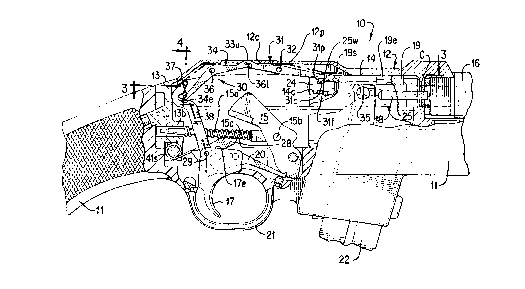
Fig. 1 is a right side elevational view of the firearm
of the present invention (with a portion of the barrel not
shown);
Fig. 2 is a partial sectional elevational view of the
locking arrangement in lock position with the hammer cocked
and the trigger at rest;
SUBSTITUtE SHEET (RULE 26)

CA 02250503 1998-09-29
WO 97/37191 PCT/US97/04336
Fig. 3 is a sectional view taken along line 3-3 of Fig.
2;
Fig. 4 is a sectional view taken along line 4-4 of Fig.
2;
Fig. 5 is an enlarged view similar to Fig. 2 with the
trigger pulled and the hammer in the fire position; and
Fig. 6 is an enlarged view similar to Fig. 2 with the
bolt manually withdrawn using the cocking handle; and
Fig. 7 is a perspective view of the bolt, the firing
pin, the bolt handle and the lock lever.
Description of the Preferred Embodiment
In Figs. 1-4, carbine 10 includes stock 11, receiver 12,
receiver blister 12b, receiver blister opening 12c, receiver
mount block 13 with forward blister 13b, bolt 14, barrel 16,
cartridge C, trigger 17, trigger body 17e and trigger return
spring 17s. Also shown are hammer 15, hammer strut 15a,
hammer strut mount 15b, hammer spring 15c, bolt cocking
handle 19, sear 20, trigger guard 21, cartridge extractor 18
and magazine 22.
Turning in particular to Figs. 2, 3, and 7, bolt 14 has
internal bolt cavity 14c for housing reciprocating firing pin
24. Bolt 14 has upper bolt notch 25 with slot 25s for
receiving cocking handle extension 19e and notch 25 also
3o includes a vertical stop wall 25w. Cocking handle 19e has
rear sloping cam surface 19s and forward angled surface 19r.
Firing pin 24 has recess notch 24n. To prevent bolt 14 from
moving rearwardly should carbine l0 be dropped or jolted and
to prevent firing pin 24 from moving forward unless trigger
17 is pulled, bolt and pin locking arrangement 30 secures
bolt 14 and pin 24 until trigger 17 is pulled or cocking
handle 19 is pulled back. Cylindrical post 35 on bolt 14 is
- 2 -
SUBSTITUTE SHEET (RULE 26)

CA 02250503 1998-09-29
WO 97/37191 PCT/US97/04336
connected to a recoil spring and associated parts (not shown)
which spring urges bolt 14 against cartridge C.
As shown in Fig. 2, locking arrangement 30 includes (1)
pin-bolt first lock lever 31 pivotally mounted on pivot pin
32 positioned in lever hole 32h; (2) second rearward lever 34
also pivotally mounted on a pin 36 also in blister 12b; (3) a
substantially vertically positioned hooked actuator member 38
pivotal about pin 29 on trigger body 17e. Actuator member 38
has upper socket opening 37 to receive lever head 34e of
lever 34. First lock lever 31 carries at its forward end a
vertical bolt stop face 31f, a sloping cam wall 31c and a
hook portion 31p with vertical hook surface 31h (see also
Fig. 7). Also shown is disconnect member 28 pivoted on pin
29 and urged counterclockwise by trigger spring 41 (Fig. 5).
Fig. 2 illustrates locking arrangement 30 in its lock
position, with lock lever stop face 31f abutting (or slightly
spaced from) bolt stop wall 25w. In this position, bolt 14
can be moved rearward only a small distance until stop wall
25w abuts bolt stop surface 31f. Any further movement of
bolt 14 is thereafter prevented by locking arrangement 30.
At the same time, lever 31 engages firing pin 24 as lever
hook piece 31p engages pin notch surface 24n. Such
engagement prevents firing pin 24 from moving forward to a
firing position where it might strike a cartridge in the
firing chamber.
First lock lever 31 has rearward end upper and lower
projections 33u, 331 which cooperate with complementary upper
and lower projections 36u, 361 of second lever 34 to cause
the levers 31, 34 to move together. Projections 33u, 331,
36u, 361 are accommodated in receiver opening 12c which
opening may be covered by a scope mount. Second lever 34 has
rearward end 34e which rides in opening 37 of linkage member
38.
- 3 -
SUBSTITUTE SHEET (RULE 26)

CA 02250503 1998-09-29
WO 97/37191 PCT/US97/04336
Turning now to Fig. 5, the operation of lock arrangement
30 to release bolt 14 and pin 24 is shown. As trigger 17 is
pulled, trigger body 17e is rotated clockwise about pin 50
and raised causing actuator 38 to also rise with its socket
opening 37 in turn carrying lever head 34h upward. Actuator
member 38 thereby causes second lever 34 to rotate about pin
36 which causes first lever 31 to rotate in the opposite
direction to raise the forward end of first lever 31
releasing bolt 14 and pin 24. During such operation, trigger
l0 movement further causes disconnect member 28 to rotate to
turn sear 20 releasing hammer 15. Hammer 15 is urged by
spring 15c against inertial firing pin 24 which moves forward
to strike the cartridge to fire carbine 10. Immediately
after firing, bolt 14 commences moving rearwardly from the
gas pressure of firing, which movement is not interfered with
since trigger 17 is still in its pulled position.
Finally, Fig. 6 shows bolt 14 fully retracted and ready
to commence the reloading portion of the carbine's cycle.
Lever 31 lies on bolt upper surface 14u (see also Fig. 7).
In operation of carbine 10, bolt 14 is capable of
automatic retraction when trigger 17 is pulled and carbine
fires, or when by manual retraction cocking handle 19 is
pulled back. Either actions will rotate lock lever 31 to
allow bolt 14 to move rearwardly through its full travel.
Pulling of cocking handle 19 is resisted in its rearward
movement by handle spring 23 shown in Fig. 3. Since cocking
handle 19 has a small mass, it does not move a significant
distance rearwardly against spring 23 if butt plate of
carbine 10 is struck. Bolt 14 is urged against cartridge C
by a large recoil spring (not shown) linked to bolt 14
through cylindrical post 35.
- 4 -
SUBSTITUTE SHEET (RULE 26)

Representative Drawing
A single figure which represents the drawing illustrating the invention.
Administrative Status

2024-08-01:As part of the Next Generation Patents (NGP) transition, the Canadian Patents Database (CPD) now contains a more detailed Event History, which replicates the Event Log of our new back-office solution.

Please note that "Inactive:" events refers to events no longer in use in our new back-office solution.

For a clearer understanding of the status of the application/patent presented on this page, the site Disclaimer , as well as the definitions for Patent , Event History , Maintenance Fee  and Payment History  should be consulted.

Event History

Description Date
Time Limit for Reversal Expired 2006-03-20
Letter Sent 2005-03-18
Grant by Issuance 2005-01-25
Inactive: Cover page published 2005-01-24
Inactive: Final fee received 2004-11-09
Pre-grant 2004-11-09
Notice of Allowance is Issued 2004-05-11
Letter Sent 2004-05-11
Notice of Allowance is Issued 2004-05-11
Inactive: Approved for allowance (AFA) 2004-04-21
Letter Sent 2002-03-11
Request for Examination Received 2002-02-07
Request for Examination Requirements Determined Compliant 2002-02-07
All Requirements for Examination Determined Compliant 2002-02-07
Inactive: IPC assigned 1998-12-09
Classification Modified 1998-12-09
Inactive: First IPC assigned 1998-12-09
Inactive: Notice - National entry - No RFE 1998-11-26
Application Received - PCT 1998-11-24
Application Published (Open to Public Inspection) 1997-10-09

Abandonment History

There is no abandonment history.

Maintenance Fee

The last payment was received on 2004-03-18

Note : If the full payment has not been received on or before the date indicated, a further fee may be required which may be one of the following

  • the reinstatement fee;
  • the late payment fee; or
  • additional fee to reverse deemed expiry.

Please refer to the CIPO Patent Fees web page to see all current fee amounts.

Fee History

Fee Type Anniversary Year Due Date Paid Date
Basic national fee - standard 1998-09-29
Registration of a document 1998-09-29
MF (application, 2nd anniv.) - standard 02 1999-03-18 1999-03-17
MF (application, 3rd anniv.) - standard 03 2000-03-20 2000-02-21
MF (application, 4th anniv.) - standard 04 2001-03-19 2001-02-19
Request for examination - standard 2002-02-07
MF (application, 5th anniv.) - standard 05 2002-03-18 2002-02-18
MF (application, 6th anniv.) - standard 06 2003-03-18 2003-03-03
MF (application, 7th anniv.) - standard 07 2004-03-18 2004-03-18
Final fee - standard 2004-11-09
Owners on Record

Note: Records showing the ownership history in alphabetical order.

Current Owners on Record
STURM, RUGER & COMPANY, INC.
Past Owners on Record
JAMES MCGARRY
MICHAEL SMISKO
WILLIAM B. RUGER
Past Owners that do not appear in the "Owners on Record" listing will appear in other documentation within the application.
Documents

To view selected files, please enter reCAPTCHA code :


To view images, click a link in the Document Description column. To download the documents, select one or more checkboxes in the first column and then click the "Download Selected in PDF format (Zip Archive)" or the "Download Selected as Single PDF" button.

List of published and non-published patent-specific documents on the CPD .

If you have any difficulty accessing content, you can call the Client Service Centre at 1-866-997-1936 or send them an e-mail at CIPO Client Service Centre.


Document
Description 
Date
(yyyy-mm-dd) 
Number of pages   Size of Image (KB) 
Representative drawing 1998-12-11 1 27
Abstract 1998-09-29 1 62
Description 1998-09-29 4 181
Claims 1998-09-29 2 64
Drawings 1998-09-29 7 259
Cover Page 1998-12-11 1 59
Cover Page 2004-12-22 1 59
Reminder of maintenance fee due 1998-11-25 1 110
Notice of National Entry 1998-11-26 1 192
Courtesy - Certificate of registration (related document(s)) 1998-11-26 1 114
Reminder - Request for Examination 2001-11-20 1 118
Acknowledgement of Request for Examination 2002-03-11 1 180
Commissioner's Notice - Application Found Allowable 2004-05-11 1 161
Maintenance Fee Notice 2005-05-16 1 172
PCT 1998-09-29 8 285
Fees 2000-02-21 1 45
Fees 1999-03-17 1 34
Fees 2004-03-18 1 35
Correspondence 2004-11-09 1 33