Note: Descriptions are shown in the official language in which they were submitted.
CA 022~0899 1998-10-02
SPECIFICATION
Control Method and Control Apparatus
for a Construction Machine
Technical Field
This invention relates to a construction machine
such as a hydraulic excavator for excavating the ground,
and more particularly to a control method and a control
apparatus for a construction machine of the type
mentioned.
A construction machine such as a hydraulic
excavator has a construction wherein it includes, for
example, as schematically shown in FIG. 13, an upper
revolving unit 100 with an operator cab (cabin) 600
provided on a lower traveling body 500 having caterpillar
members 500A, and further, a joint type arm mechanism
composed of a boom 200, a stick 300 and a bucket 400 is
provided on the upper revolving unit 100.
And, based on expansion/contraction displacement
information of the boom 200, stick 300 and bucket 400
obtained, for example,by stroke sensors 210, 220 and 230,
the boom 200, stick 300 and bucket 400 can be driven
suitably by hydraulic cylinders 120, 121 and 122,
respectively, to perform an excavating operation while
the advancing direction of the bucket 400 or the posture
of the bucket 400 is kept fixed so that control of the
CA 022~0899 1998-10-02
position and the posture of a working member such as the
bucket 400 can be performed accurately and stably.
By the way, in such a conventional hydraulic
excavator as described above, when an operation (raking)
of moving a top of the bucket 400 linearly such as, for
example, a horizontal leveling operation is performed
automatically by a controller, solenoid valves (control
valve mechanisms) in a hydraulic circuit which supplies
and discharges working oil to and from the hydraulic
10cylinders 120, 121 and 122 are electrically feedback
controlled to control the expansion/contraction
operations of the hydraulic cylinders 120, 121 and 122
to control the postures of the boom 200, stick 300 and
bucket 400.
15In this instance, the hydraulic cylinders 120, 121
and 122 are connected to the hydraulic circuits and are
operated by a delivery pressure from a pump, and when an
operator operates an operation lever, supply or discharge
of the working oil to or from the hydraulic cylinders 120
to 122 is performed through the hydraulic circuit so that
the boom 200, stick 300 and bucket 400 operate.
And, immediately before driving of the joint type
arm mechanism is started, the operation lever is disposed
in aneutralposition (non-drivingposition), andthepump
26 mentioned above is in a condition (idling condition)
wherein it little delivers the working oil. If the
operation leveris operated fromthe condition described,
. .
CA 022~0899 1998-10-02
then the delivery pressure of the pump gradually rises
in response to the operation amount of the operation
lever.
Consequently, immediately after the operation
lever is operated from the idling condition of the pump
to start automatic control (immediately after driving is
started), since the delivery pressure of the pump does
not exhibit a sufficient rise, a response delay of the
pump occurs, and besides, due to the fact that the pump
load is lower than the loads to the hydraulic cylinders
120 to 122, the dead zone is increased, resulting in
deterioration of the posture control accuracy of the
bucket 400. Accordingly, it is difficult to improve the
finish accuracy of a horizontally leveled surface or the
like by the bucket 400 immediately after driving is
started.
The present invention has been made in view of such
a subject as described above, and it is an object of the
present invention to provide a control method and a
control apparatus for a construction machine by which,
even immediately after driving of an arm mechanism is
started, a response delay of a pump or an increase of a
dead zone is suppressed to achieve improvement in the
finish accuracy by a working member.
Disclosure of Invention
In order to attain the object described above,
CA 022~0899 1998-10-02
according to the present invention, a control method for
a construction machine wherein ajoint type arm mechanism
provided on a construction machine body is driven by a
cylinder type actuator which is connected to a fluid
pressure circuit having a pump, whose delivery pressure
is variable in response to an operation amount by an
operation member,andisoperatedbythedeliverypressure
from the pump, is characterized in that the delivery
pressure ofthe pump is maintained equal to or higher than
a predetermined value also when the operation member is
in a non-driving position for the cylinder type actuator.
In the control method for a construction machine
described above, also when the operation member is in the
non-driving position for the cylinder type actuator, the
delivery pressure is maintained equal to or higher than
the predetermined value, and consequently, even
immediately after the operation member is operated from
the non-driving position (immediately after driving is
started) in orderto operatethejoint type arm mechanism,
a sufficient pump delivery pressure is obtained and a
response delay of the pump or an increase of the dead zone
can be suppressed.
Accordingly, even immediately after driving of the
arm mechanism is started, deterioration of the posture
control accuracy of the working member can be prevented,
and the finish accuracy by the working member can be
enhanced remarkably.
CA 022~0899 1998-10-02
Meanwhile, a control apparatus for a construction
machine of the present invention is characterized in that
it comprises a construction machine body, a joint type
arm mechanism pivotally mounted at an end portion thereof
on the construction machine body and having a working
member at the other end side thereof, a cylinder type
actuator mechanism for performing an
expansion/contraction operation to drive the arm
mechanism, an operation member for operating the arm
mechanism through the cylinder type actuator mechanism,
a fluid pressure circuit having a pump whose delivery
pressure is variable in response to an operation amount
by the operation member for supplying and discharging
working fluid to and from the cylinder type actuator
mechanism to cause the cylinder type actuator mechanism
to perform an expansion/contraction operation, detection
means for detecting whether or not the operation member
is in a non-driving position for the cylinder type
actuator mechanism, and pump control means for
maintaining, when it is detected by the detection means
that the operation member is in the non-driving position
for the cylinder type actuator mechanism, the delivery
pressure of the pump equal to or higher than a
predetermined value.
It is to be noted that the pump control means
described above may be constructed such that it maintains
the delivery pressure of the pump equal to or higher than
CA 022~0899 1998-10-02
the predetermined value if it is detectedby the detection
means that the operation member is in the non-driving
position for the cylinder type actuator mechanism and it
is detected that a control starting triggering operation
by acontrolstartingtriggeringoperation memberhasbeen
performed.
Further, the pump control means described above may
be constructed such that it varies the delivery pressure
to be maintained in response to a condition of a load
acting upon the cylinder type actuator mechanism, and in
this instance, the pump control means may be constructed
such that it includes storage means in which the
maintained delivery pressure to be varied in response to
the condition of the load acting upon the cylinder type
actuator mechanism.
In the control apparatus for a construction machine
of the present invention described above, if it is
detected by the detection means described above that the
operation member is in the non-driving position for the
cylinder type actuator mechanism, the delivery pressure
of the pump is maintained equal to or higher than the
predetermined value by the pump control means, and
consequently,evenimmediately aftertheoperation member
is operated from the non-driving position (immediately
after driving is started) in order to operate the joint
type arm mechanism, a sufficient pump delivery pressure
is obtained and a response delay ofthepump or an increase
CA 022~0899 1998-10-02
of the dead zone can be suppressed.
Accordingly, also in this instance, even
immediately afterdrivingofthe armmechanismisstarted,
deterioration of the posture control accuracy of the
working member can be prevented, and the finish accuracy
by the working member can be enhanced remarkably.
It is to be noted that, where the pump control means
maintains the delivery pressure of the pump equal to or
higher than the predetermined value when it is detected
by the detection means described above that the operation
member is in the non-driving position for the cylinder
type actuator mechanism and it is detected that a control
starting triggering operation by the control starting
triggering operation member has been performed, whether
or not the control operation of the pump control means
for maintaining the delivery pressure of the pump equal
to or higher than the predetermined value when the
operation member is in the non-driving position can be
selected by a control starting triggering operation by
the control starting triggering operation member.
Accordingly,onlywhen anoperatororthelikewants,
the control operation by the pump control means can be
performed, and the delivery pressure of the pump need not
be held to an unnecessarily high pressure condition and
efficient operation can be achieved.
Further, where the pump control means varies the
delivery pressure to be maintained in response to a
CA 022~0899 1998-10-02
condition of the load acting upon the cylinder type
actuator mechanism, an increase of the dead zone which
arises from the fact that the pump load is lower than the
load to the cylinder type actuator mechanism can be
suppressed with certainty, and consequently, the control
apparatus for a construction machine contributes very
much to enhancement of the finish accuracy by the working
member.
In this instance, where the maintained delivery
pressure to be varied in response to the condition of the
load acting upon the cylinder type actuator mechanism is
stored in advance in the storage means, the pump control
means can obtain an optimum delivery pressure to be
maintained of the pump and perform variation control of
16 the delivery pressure of the pump only if it reads out
the delivery pressure to be maintained corresponding to
the condition of the load acting upon the cylinder type
actuator mechanism from the storage means.
Brief Description of the Drawings
FIG. 1 is a schematic view of a hydraulic excavator
on which a control apparatus according to an embodiment
of the present invention is mounted;
FIG. 2 is a view schematically showing a general
construction (electric system and hydraulic system) of
the control apparatus according to the embodiment of the
present invention;
CA 022~0899 1998-10-02
FIG. 3 is a block diagram schematically showing a
general construction of the control apparatus according
to the embodiment of the present invention;
FIG.4isablockdiagram forexplaininga functional
6 construction of the entire control apparatus according
to the embodiment of the present invention;
FIG. 6 is a control block diagram of essential part
of the control apparatus according to the embodiment of
the present invention;
FIG. 6 is a block diagram for explaining a
characteristic function of the control apparatus
according to the embodiment of the present invention and
aconstruction ofessentialpart relatingtothe function;
FIG. 7 is a side elevational view showing operating
parts (a joint type arm mechanism and a bucket) of the
hydraulic excavator according to the present embodiment;
FIG. 8 is a side elevational view schematically
showing the hydraulic excavator in order to explain
operation of the hydraulic excavator according to the
present embodiment;
FIG. 9 is a side elevational view schematically
- showing the hydraulic excavator in order to explain
operation of the hydraulic excavator according to the
present embodiment;
2~ FIG. 10 is a side elevational view schematically
showing the hydraulic excavator in order to explain
operation of the hydraulic excavator according to the
CA 022~0899 1998-10-02
present embodiment;
FIG. 11 is a side elevational view schematically
showing the hydraulic excavator in order to explain
operation of the hydraulic excavator according to the
5present embodiment;
FIG. 12 is a side elevational view schematically
showing the hydraulic excavator in order to explain
operation of the hydraulic excavator according to the
present embodiment; and
10FIG. 13 is a side elevational view schematically
showing a general construction of a conventional
hydraulic excavator.
Best Mode for Carrying out the Invention
15In the following, an embodiment of the present
invention is described with reference to the drawings.
A hydraulic excavator as a construction machine
accordingtothepresentembodimentincludes,forexample,
as schematically shown in FIG. 1, an upper revolving unit
20(construction machine body) 100 with an operator cab 600
for revolving movement in a horizontal plane on a lower
traveling body 600 which has caterpillar members 500A on
the left and right thereof.
A boom (arm member) 200 having one end connected
25for swinging motion is provided on the upper revolving
unit 100, and a stick (arm member) 300 connected at one
endthereof forswingingmotionby ajoint part isprovided
CA 022~0899 1998-10-02
on the boom 200.
A bucket (working member) 400 which is connected
at one end thereof for swinging motion by a joint part
and can excavate the ground with a tip thereof and
accommodate earth and sand therein is provided on the
stick 300.
In this manner, a joint type arm mechanism which
is mounted at one end portion thereof for pivotal motion
on the upper revolving unit 100 and has the bucket 400
on the other end side thereof and further has the boom
200 and the stick 300 as a pair of arm members connected
to each other by the joint part is composed of the boom
200, stick 300 and bucket 400.
Further, a boom hydraulic cylinder 120, a stick
hydraulic cylinder 121 and a bucket hydraulic cylinder
122 (in the following description, the boom hydraulic
cylinder 120 may be referred to as boom cylinder 120 or
merely as cylinder 120, the stick hydraulic cylinder 121
may be referred to as stick cylinder 121 or merely as
cylinder 121, and the bucket hydraulic cylinder 122 may
be referredto asbucketcylinder122ormerely ascylinder
122) as cylinder type actuators are provided.
Here, the boom cylinder 120 is connected at one end
thereof for swinging motion to the upper revolving unit
26 100 and is connected- at the other one end thereof for
swinging motion to the boom 200, or in other words, the
boom cylinder 120 is interposed between the upper
CA 022~0899 1998-10-02
12
revolving unit 100 and the boom 200, such that, as the
distance between the opposite end portions is expanded
or contracted, the boom 200 can be swung with respect to
the upper revolving unit 100.
The stick cylinder 121 is connected at one end
thereof for swinging motion to the boom 200 and connected
at the other one end thereof for swinging motion to the
stick 300, or in other words, the stick cylinder 121 is
interposed between the boom 200 and the stick 300, such
that, as the distance between the opposite end portions
is expanded or contracted, the stick 300 can be swung with
respect to the boom 200.
The bucket cylinder 122 is connected at one end
thereof for swingingmotion tothe stick 300 and connected
at the other one end thereof for swinging motion to the
bucket 400, or in other words, the bucket cylinder 122
is interposed between the stick 300 and the bucket 400,
such that, as the distance between the opposite end
portions thereof is expanded or contracted, the bucket
400 can be swung with respect to the stick 300. It is
to be noted that a linkage 130 is provided at a free end
portion of the bucket hydraulic cylinder 122.
In this manner, a cylinder type actuator mechanism
having a plurality of cylinder type actuators for driving
the arm mechanism by performing expanding or contracting
operations is composed of the cylinders 120 to 122
described above.
CA 022~0899 1998-10-02
Itistobenotedthat,thoughnotshowninthe figure,
also hydraulic motors for driving the left and right
caterpillarmembers600Aandarevolvingmotor for driving
the upper revolving unit 100 to revolve are provided.
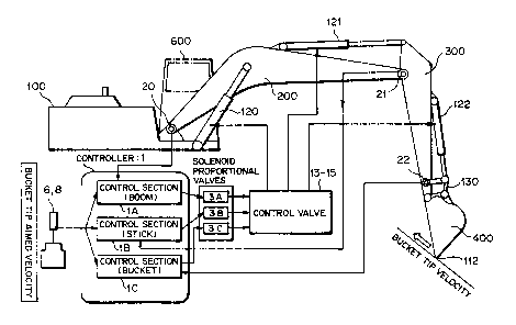
5By the way, as shown in FIG. 2, a hydraulic circuit
(fluid pressure circuit) for the cylinders 120 to 122,
the hydraulic motors and the revolving motor described
above is provided, and in addition to pumps 51 and 52 of
the variable delivery pressure type which are driven by
10an engine E, a boom main control valve (control valve)
13, astickmain controlvalve (controlvalve) 14, abucket
main control valve (control valve) 15 and so forth are
interposed in the hydraulic circuit. The pumps 51 and
52 of the variable delivery pressure type are each
15constructed such that the camp plate angle (tilt angle)
is controlled by an engine pump controller 27 which will
be hereinafter described so that the delivery pressure
of working oil to the hydraulic circuit can be varied.
It is to be noted that, where each line which
20interconnects different componentsis asolidlineinFIG.
2, this represents that this line is an electric system,
but where each line which interconnects different
components is abroken line, this represents that the line
is a hydraulic system.
25Further, in ordertocontrolthemain control valves
13, 14 and 15, a pilot hydraulic circuit is provided, and
in addition to a pilot pump 50 driven by the engine E,
CA 022~0899 1998-10-02
14
solenoid proportional valves 3A, 3B and 3C, solenoid
directional switch valves 4A, 4B and 4C, selector valves
18A, 18B and 18C and so forth are interposed in the pilot
hydraulic circuit.
In the hydraulic excavator of the present
embodiment, a controller 1 for controlling the main
control valves 13, 14 and 15 viathe solenoid proportional
valves 3A, 3B and 3C to control the boom 200, the stick
300 and the bucket 400 in response to a mode in which they
should be controlled so that they may have desired
expansion/contraction displacements is provided. It is
to be noted that the controller 1 is composed of a
microprocessor, memories such as a ROM and a RAM, suitable
input/output interfaces and so forth.
To the controller 1, detection signals (including
setting signals) from various sensors are inputted, and
the controller 1 executes the control described above
based on the detection signals from the sensors. It is
to be notedthat such controlby the controller 1 is called
semiautomatic control, and even during excavation under
the semiautomatic control (semiautomatic excavation
mode), it is possible to manually effect fine adjustment
of a bucket angle and an aimed slope face height.
Assuch a semiautomaticcontrol mode (semiautomatic
excavation mode) as described above, a bucket angle
control mode (refer to FIG. 8), a slope face excavation
mode (bucket tip linear excavation mode or raking mode;
CA 022~0899 1998-10-02
refer to FIG. 9), a smoothing mode which is a combination
of the slope face excavation mode and the bucket angle
control mode (refer to FIG. 10), a bucket angle automatic
return mode (automatic return mode; refer to FIG. 11) and
so forth are available.
Here, the bucket angle control mode is a mode in
which the angle (bucket angle) of the bucket 400 with
respect to the horizontal direction (vertical direction)
is always kept constant even if the stick 300 and the boom
200 are moved as shown in FIG. 8, and this mode is executed
if a bucket angle control switch on a monitor panel 10
which will be hereinafter described is switched ON. It
is to be noted that this mode is cancelled when the bucket
400 is moved manually, and a bucket angle at a point of
time when the bucket 400 is stopped is stored as a new
bucket holding angle.
The slope face excavation mode is a mode in which
a tip 112 (which may sometimes be referred to as bucket
tip 112) of the bucket 400 moves linearly as shown in FIG.
9. However, the bucket cylinder 122 does not move.
Further,thebucket angle0variesasthebucket 400moves.
The slope face excavation mode + bucket angle
control mode (smoothing mode) is a mode in which the tip
112 of the bucket 400 moves linearly and also the bucket
2~ angle 0 is kept constant during excavation as shown in
FIG. 10.
The bucket automatic return mode is a mode in which
CA 022~0899 1998-10-02
16
the bucket angle is automatically returned to an angle
set in advance as shown in FIG. 11, and the return bucket
angle is set by the monitorpanel 10. This mode is started
when a bucket automatic return start switch 7 on a
5 boom/bucket operation lever 6 is switched ON. This mode
is cancelled at a point oftime whenthebucket 400 returns
to the angle set in advance.
The slope face excavation mode and the smoothing
mode described above are entered when a semiautomatic
control switch on the monitor panel 10 is switched ON and
aslope face excavation switch9ona stickoperation lever
8 is switched ON and besides both or either one of the
stick operation lever 8 and the boom/bucket operation
lever 6 is moved. It is to be noted that the aimed slope
face angle is set by a switch operation on the monitor
panel 10.
Further, in the slope face excavation mode and the
smoothing mode, the operation amount of the stick
operation lever 8 provides a bucket tip moving velocity
in a parallel direction to the aimed slope face angle,
and the operation amount of the boom/bucket operation
lever 6 provides a bucket tip moving velocity in the
perpendicular direction. Accordingly, if the stick
operation lever 8 is moved, then the bucket tip 112 starts
its linear movement along the aimed slope face angle, and
fine adjustment of the aimed slope face height by a manual
operation can be performed by moving the boom/bucket
CA 022~0899 1998-10-02
operation lever 6 during excavation.
Furthermore, in the slope face excavation mode and
the smoothing mode, not only the bucket angle during
excavation can be adjusted finely, but also the aimed
slope face height can be changed, by operating the
boom/bucket operation lever 6.
It is to be noted that, in the present system, also
a manual mode is possible, and in this manual mode, not
only operation equivalent to that of a conventional
hydraulic excavator is possible, but also coordinate
indication of the bucket tip 112 is possible.
Also a service mode for performing service
maintenance of the entire semiautomatic system is
prepared, and this service mode is enabled by connecting
an external terminal 2 to the controller 1. And, by this
servicemode, adjustmentofcontrol gains,initialization
of various sensors and so forth are performed.
By the way, as the various sensors connected to the
controller 1, as shown in FIG. 2, pressure switches 16,
pressuresensorsl9,28Aand28B,resolvers(anglesensors,
posture detection means) 20 to 22, a vehicle inclination
angle sensor 24 and so forth are provided. Further, to
the controller 1,the engine pump controller 27, an ON-OFF
switch (bucket automatic return start switch described
above) 7, another ON-OFF switch (slope face excavation
switch described hereinabove) 9, the monitor panel
(display switch panel) 10 with an aimed slope face angle
CA 022~0899 1998-10-02
18
setting unit are connected. It is to be noted that the
external terminal 2 is connected to the controller 1 upon
adjustment of the control gains, initialization of the
sensors and so forth.
The engine pump controller 27 receives engine speed
information from an engine speed sensor 23 and controls
the cam plate angles (tilt angles) of the engine E and
the pumps 51 and 52 of the variable delivery pressure type
described above. The engine pump controller 27 can
communicate coordination information with the controller
1.
The pressure sensors 19 are attached to pilot pipes
connected from the operation levers 6 and 8 for
expansion/contraction of the stick 300 and for
upward/downward movement of the boom 200 to the main
control valves 13, 14 and 15 and detect pilot hydraulic
pressures in the pilot pipes. Since the pilot hydraulic
pressures in such pilot pipes are varied by the operation
amounts of the operation levers 6 and 8, by measuring the
hydraulic pressures, the controller 1 can estimate the
operation amounts of the operation levers 6 and 8 based
on the measured hydraulic pressures.
The pressure sensors 28A and 28B detect
expansion/contraction conditionsoftheboomcylinder120
and stick cylinder 121, respectively, and the load
conditions acting upon the cylinders 120 and 121 can be
detected by the pressure sensors 28A and 28B,
CA 022~0899 1998-10-02
19
respectively.
It is to be noted that, upon the semiautomatic
control described above, the stick operation lever 8 is
used to determine the bucket tip moving velocity in a
5 parallel direction with respect to a set excavation slant
face, and the boom/bucket operation lever 6 is used to
determine the bucket tip moving velocity in the
perpendicular direction with respect to the set slant face.
Accordingly, when the stick operation lever 8 and the
10 boom/bucket operation lever 6 are operated simultaneously,
the moving direction and the moving velocity of the bucket
tip are determined by a composite vector in the parallel
and perpendicular directions with respect to the set slant
face.
The pressure switches 16 are attached to the pilot
pipes for the operation levers 6 and 8 for the boom 200,
stick 300 and bucket 400 with selector valves 17 or the
like interposed therebetween and are used to detect
whether or not the operation levers 6 and 8 are in a neutral
20 condition. In particular, when the operation lever 6 or
8 is in the neutral condition, the output of the pressure
switch 16 is OFF, but when the operation lever 6 or 8 is
used, the output of the pressure switch 16 is ON. It is
to be noted that the pressure switches 16 for detection
25 of a neutral condition are used also for detection of an
abnormal condition of the pressure sensors 19 and for
switching between the manual/semiautomatic modes.
CA 022~0899 1998-10-02
The resolver 20 is provided at a pivotally mounted
portion (joint part) of the boom 200 on the construction
machine body 100 at which the posture of the boom 200 can
be monitored and functions posture detection means for
detecting the posture of the boom 200. The resolver 21
is provided at a pivotally mounted portion (joint part)
of the stick 300 on the boom 200 at which the posture of
the stick 300 can be monitored and functions as posture
detection means for detecting the posture of the stick
300. Further, the resolver 22 is provided at a linkage
pivotally mounted portion at which the posture of the
bucket 400 can be monitored and functions as posture
detection means for detecting the posture of the bucket
400. By those resolvers 20 to 22, angle detection means
for detecting the posture of the arm mechanism in angle
information is composed.
A signal converter 26 converts angle information
obtained by the resolver 20 into expansion/contraction
displacement information of the boom cylinder 120,
converts angle information obtained by the resolver 21
into expansion/contraction displacement information of
the stick cylinder 121, and converts angle information
obtained by the resolver 22 into expansion/contraction
displacement information ofthe bucket cylinder 122, that
is, converts angle information obtained by the resolvers
to 22 into corresponding expansion/contraction
displacement information of the cylinders 120 to 122.
CA 022~0899 1998-10-02
21
To this end, the signal converter 26 includes an
input interface 26A for receiving signals from the
resolvers 20 to 22, a memory 26B which includes a lookup
table 26B-l for storing expansion/contraction
displacement information of the cylinders 120 to 122
corresponding to angle information obtained by the
resolvers 20 to 22, a main arithmetic unit (CPU) 26C which
can calculate the expansion/contraction displacement
information of the cylinders 120 to 122 corresponding to
angle information obtained by the resolvers 20 to 22 and
communicate the cylinder expansion/contraction
displacement information with the controller 1, and an
output interface 26D for sending out the cylinder
expansion/contraction displacement information from the
1~ CPU 26C.
The expansion/contraction displacement
information Abm, Ast and Abk of the cylinders 120 to
122 corresponding to the angle information Obm, ~st and
~bk obtained by the resolvers 20 to 22 described above
can be calculated using the cosine theorem in accordance
with the following expressions (1) to (3):
Abm = (L~ol/lo22 t L~ol/lll2
- 2LIol/lo2 Llol/lllcos(obm + Axbm)) 1/2
~-- (1)
Ast = (L~o3/lo42 t L~o4~os2- 2L~o3~lo4-Llo4/loscos~st) 112
~ - (2)
Abk = (Llo6/lo72 t L~07/~o92- 2L~o6/lo7-L~o7/losC~S~bk) 1/2
CA 022~0899 1998-10-02
~ - (3)
Here, in the expressions above, Li~j represents a
fixed length, Axbm represents a fixed angle, and the
suffix i/j to L has information between the nodes i and
j. For example, Llol/l02 represents the distance between
the node 101 and the node 102. It is to be noted that
the node 101 is determined as the origin of the xy
coordinate system (refer to FIG. 7).
Naturally, each time the angle information ~bm,
~st and ~bk is obtained by the resolvers 20 to 22, the
expressions above may be calculated by arithmetic means
(for example, the CPU 26C). In this instance, the CPU
26C forms the arithmetic means which calculates, based
on the angle information obtained by the resolvers 20 to
22, expansion/contraction displacement information of
the cylinders 120 to 122 corresponding to the angle
information by calculation.
It is to be noted that signals obtained by the
conversion by the signal converter 26 are utilized not
only for feedback control upon semiautomatic control but
also to measure coordinates for measurement/indication
of the position of the tip 112 of the bucket 400.
The position of the bucket tip 112 (the position
may be hereinafter referredto as bucket tip position 112)
in the semiautomatic system is calculated using a certain
point of the upper revolving unit 100 of the hydraulic
excavator as the origin. However, when the upper
CA 022~0899 1998-10-02
23
revolving unit 100 is inclined in the front linkage
direction, it isnecessary to rotatethecoordinate system
for control calculation by an angle by which the vehicle
is inclined. The vehicle inclination angle sensor 24 is
used to correct the coordinate system for an amount of
the rotation of the coordinate system.
While the solenoid proportional valves 3A to 3C
control the hydraulic pressures supplied from the pilot
pump 50 in response to electric signals from the
controller 1 and the controlled hydraulic pressures act
upon the main control valves 13, 14 and 15 through the
switch valves 4A to 4C or the selector valves 18A to 18C
to control the spool positions of the main control valves
13, 14 and 15 so that aimed cylinder velocities may be
16 obtained, if the control valves 4A to 4C are set to the
manual mode side, then the cylinders 120 to 122 can be
controlled manually.
It is to be noted that a stick confluence control
proportional valve 11 adjusts the confluence ratio of the
two pumps 51 and 52 in order to obtain an oil amount
corresponding to an aimed cylinder velocity.
Further, the ON-OFF switch (slope face excavation
switch) 9 described hereinabove is mounted on the stick
operation lever 8, and as an operator operates the switch
9,asemiautomaticmodeisselectedornot selected. Then,
if a semiautomatic mode is selected, then the tip 112 of
the bucket 400 can be moved linearly.
CA 022~0899 1998-10-02
24
Furthermore, the ON-OFF switch (bucket automatic
return start switch) 7 described hereinabove is mounted
on the boom/bucket operation lever 6, and as an operator
switches on the switch 7, the bucket 400 can be
automatically returned to an angle set in advance.
Safety valves 5 are provided to switch the pilot
pressures to be supplied to the solenoid proportional
valves 3A to 3C, and only when the safety valves 5 are
in an ON state, the pilot pressures are supplied to the
solenoidproportional valves3Ato 3C. Accordingly, when
some failure occurs or in a like case in the semiautomatic
control, automatic control of the linkage can be stopped
rapidly by switching the safety valves 6 to an OFF state.
The speed of the engine E is different depending
upontheposition oftheenginethrottleset by an operator
[the position is set by operating a throttle dial (not
shown)], and further, even if the position of the engine
throttle is fixed, the engine speed varies depending upon
the load. Since the pumps 50, 61 and 52 are directly
connected to the engine E, if the engine speed varies,
then also the pump discharges (pump delivery pressures)
vary, and consequently, even if the spool positions of
the main control valves 13, 14 and 15 are fixed, the
cylinder velocities are varied by the variation of the
2~ engine speed. In order to correct this, the engine speed
sensor 23 is mounted, and when the engine speed is low,
the aimed moving velocity of the tip 112 of the bucket
., .
CA 022~0899 1998-10-02
400 is set slow.
The monitor panel 10 with an aimed slope face angle
setting unit (which may sometimes be referred to simply
as monitor panel 10) is not only used as a setting unit
for the aimed slope face angle ~ (refer to FIGS. 7 and
12) and the bucket return angle, but also used as an
indicator for coordinates ofthebucket tip 400, the slope
face angle measured or the distance between coordinates
oftwo points measured. It istobe notedthat the monitor
panel 10 is provided in the operator cab 600 together with
the operation levers 6 and 8.
In particular, in the system according to the
present embodiment, the pressure sensors 19 and the
pressure switches 16 are incorporated in conventional
pilot hydraulic lines to detect operation amounts of the
operation levers 6 and 8 and feedback control is effected
using the resolvers 20, 21 and 22 while multiple freedom
degree feedback control can be effected independently for
each of the cylinders 120, 121 and 122. Consequently,
the requirement for addition of an oil unit such as a
pressure compensation valve is unnecesary. Further, an
influence of inclination of the upper revolving unit 100
is corrected using the vehicle inclination angle sensor
24, and the solenoid proportional valves 3A to 3C are
utilized in order to drive the cylinders 120, 121 and 122
with electric signals from the controller 1. It is to
be noted that an operator can select a mode arbitrarily
CA 022~0899 1998-10-02
26
using the manual/semiautomatic mode change-over switch
9 and besides can set an aimed slope face angle.
In the following, a control algorithm of the
semiautomatic system performed by the controller 1 is
described. The control algorithm of the semiautomatic
control mode (except the bucket automatic return mode)
effected by the controller 1 is substantially such as
illustrated in FIG. 4.
In particular, the moving velocity and the moving
direction of the tip 122 of the bucket 400 are first
calculated based on information of the aimed slope face
set angle, the pilot hydraulic pressures for controlling
the stick cylinder 121 and the boom cylinder 120, the
vehicle inclination angle and the engine speed. Then,
aimed velocities of the cylinders 120, 121 and 122 are
calculated based on the calculated information (moving
velocity and moving direction ofthe tip 112 ofthe bucket
400). In this instance, the information of the engine
speed is required to determine an upper limit to the
cylinder velocities.
Further,thecontrollerlincludes,asshowninFIGS.
3 and 4, control sections lA, lB and lC provided
independently of each other for the cylinders 120, 121
and 122, and the controls are constructed as independent
control feedback loops as shown in FIG. 4 so that they
may not interfere with each other.
Here, essential part of the control apparatus of
CA 022~0899 1998-10-02
the present embodiment is described. The compensation
construction in the closed loop controls shown in FIG.
4 has, in each of the control sections lA, lB and lC, a
multiple freedomdegreeconstructionincludingafeedback
loop and a feedforward loop with regard to the
displacement and the velocity as shown in FIG. 6, and
includes feedback loop type compensation means 72 having
a variable control gain (control parameter), and
feedforward loop type compensation means 73 having a
variable control gain (control parameter).
In particular, if an aimed velocity is given, then
feedback loop processes according to a route wherein a
deviation between the aimed velocity and velocity
feedback information is multiplied by a predetermined
16 gain Kvp (refer to reference numeral 62), another route
wherein the aimed velocity is integrated once (refer to
an integration element 61 of FIG. 5) and a deviation
between the aimed velocity integration information and
displacement feedback information is multiplied by a
predetermined gain Kpp (refer to reference numeral 63)
and a further route wherein the deviation between the
aimed velocity integration information and the
displacement feedback information is multiplied by a
predetermined gain Kpi (refer to reference numeral 64)
26 and further integrated (refer to reference numeral 66)
areperformedbythe feedbacklooptypecompensationmeans
72 while, by the feedforward loop type compensation means
.
CA 022~0899 1998-10-02
28
73, a feedforwardloop processby aroutewhereintheaimed
velocity is multiplied by a predetermined gain Kf (refer
to reference numeral 65) is performed.
Of the processes mentioned, the feedback loop
5processes are described in more detail. The present
apparatus includes, as shown in FIG. 5, operation
information detection means 91 for detecting operation
information of the cylinders 120 to 122, and the
controller 1 receives the detection information from the
10operation information detection means 91 and aimed
operation information (for example, an aimed moving
velocity) set by aimed value setting means 80 as input
information and sets and outputs control signals so that
the arm members such as the boom 200 and the bucket
15(working member) 400 may exhibit aimed operation
conditions. Further, the operation information
detection means 91 particularly is cylinder position
detection means 83 which can detect positions of the
cylinders 120 to 122, and in the present embodiment, the
20cylinder position detection means 83 is composed of the
resolvers 20 to 22 and the signal converter 26 described
hereinabove.
It is to be noted that the values of the gains Kvp,
Kpp, Kpi and Kf can be changed by a gain scheduler 70.
25Further, while a non-linearity removal table 71 is
provided to remove non-linear properties of the solenoid
proportional valves 3A to 3C, the main control valves 13
.,
CA 022~0899 1998-10-02
29
to 15 and so forth, a process in which the non-linearity
removal table 71 is used is performed at a high speed by
a computer by using a table lookup technique.
By the way, in the control apparatus of the present
embodiment, the engine pump controller 27 and the
controller 1 cooperate with each other to provide
functions of variably controlling the delivery pressures
of the pumps 51 and 52 (functions as pump control means).
Main ones of the functions are a function 0 and another
function ~ described below:
Function 0: function of variably controlling the
delivery pressures of the pumps 51 and 52 in response to
an operation amount by the stick operation lever
(operation member) 8. The function of controlling, when
the operation lever 6 or 8 is operated from a condition
(idling condition) wherein the operation lever 6 or 8 is
disposed at its neutral position (non-driving position)
and the pumps 51 and 52 little deliver the working oil,
the cam plate angles of the pumps 51 and 52 so that the
delivery pressures of the pumps 51 and 52 may gradually
rise in response to the operation amount of the operation
lever 6 or 8.
Function ~: function of controlling the cam plate
angles of the pumps 51 and 52 so that the delivery
26 pressures of the angle pumps 51 and 52 may be held equal
toorhigherthan apredeterminedvalue (toahighpressure
condition) in response to a control starting triggering
CA 022~0899 1998-10-02
operation by a pushbutton switch 8a (refer to FIG. 6)
provided for the stick operation lever 8, a signal from
a neutral position detecting sensor (detection means) 8b
for detecting whether or not the stick operation lever
8 is in a non-driving position (neutral position; in a
position in which the pumps 51 and 52 are in an idling
condition) for the cylinders 120 and 121 and signals from
the pressure sensors 28A and 28B (load conditions of the
cylinders 120 and 121). More particularly, the function
of controlling, when the stick operation lever 8 is in
its neutral position and the pushbutton switch 8a is
depressed, the cam plate angles of the pumps 51 and 52
so that delivery pressures corresponding to the load
conditions ofthe cylinders 120 and 121may be maintained.
The latter function ~ which is a characteristic
function of the present invention is described in more
detail with reference to FIG. 6.
As shown in FIG. 6, in the present embodiment, the
neutral position detecting sensor (detection means) 8b
for detecting whether the stick operation lever 8 is in
its non-driving position (neutral position) for the
cylinders 120 and 121 and the pushbutton switch (control
starting triggering operation member) 8a which is
operated when semiautomatic control is to be started are
provided for the stick operation lever 8.
The controller 1 has a pump cam plate angle setting
table (storage means)whichwillbehereinafterdescribed,
CA 022~0899 1998-10-02
31
and when it is detected by the neutral position detecting
sensor 8b that the stick operation lever 8 is in its
neutralposition andthepushbuttonswitch 8aisdepressed
(control starting triggering operation), the controller
1 outputs a pump cam plate instruction value to the engine
pump controller 27 to control the delivery pressures of
the cylinders 120 and 121 so that the delivery pressures
may be held at delivery pressures (high pressure
condition) corresponding to the load conditions of the
cylinders 120 and 121 (maximum values ofthe cylinder load
pressures) detected by the pressure sensors 28A and 28B.
Then, the engine pump controller 27 which receives
the pump cam plate instruction value from the controller
1 actually performs control of the pumps 51 and 52 by
adjusting them so that the cam plate angles of them may
be equal to the pump cam plate instruction to maintain
the delivery pressures of the pumps 51 and 52 equal to
or higher than the predetermined value.
Thepumpcamplateanglesettingtable60 isprovided
to output a pump cam plate angle (pump cam plate
instruction value) corresponding to the load conditions
of the cylinders 120 and 121 (maximum values of the loads
in the cylinder driving direction) detected by the
pressure sensors 28A and 28B, and is stored in a memory
(for example, a ROM or a RAM), which composes the
controller 1, in advance to allow a pump cam plate angle
corresponding to a maximum value of a cylinder load
.. . ~ . . ..
CA 022~0899 1998-10-02
pressure to be read out by using a table lookup technique.
In the pump cam plate angle setting table 60, the
pump camplate angleisset suchthat the deliverypressure
of each of the pumps 61 and 52 increases as the m~xi mum
values of the cylinder load pressures detected by the
pressures sensors 28A and 28B increase as shown, for
example, in FIG. 6.
It is to be noted that, while, in the present
embodiment,thepushbutton switch8aasacontrolstarting
triggering operation member and the neutral position
detecting sensor 8b are provided for the stick operation
member 8, they may be provided for the boom/bucket
operation lever 6. Further, while, in the present
embodiment, the pump cam plate angle setting table 60 and
the function of outputting a pump cam plate instruction
value based on the table 60 are provided in the controller
1, the table 60 and the pump cam plate instruction value
outputting function may be provided in the engine pump
controller 27.
In the present embodiment having such a
construction as described above, when such a slope face
excavating operation of an aimed slope face angle ~ as
shown in FIG. 12 is performed semi-automatically using
the hydraulic excavator, in the system according to the
present invention, such semiautomatic control functions
as described above can be realized by an electronic
hydraulic system which automatically adjusts the
CA 022~0899 1998-10-02
composite moving amount of the boom 200 and the stick 300
in accordance with the excavating velocity in contrast
with a conventional system of manual control.
In particular, detection signals (including
setting information of an aimed slope face angle) are
inputted from the various sensors to the controller 1
mounted on the hydraulic excavator, and the controller
1 controls the main control valves 13, 14 and 15 through
the solenoid proportional valves 3A, 3B and 3C based on
the detection signals from the sensors (including
detection signals of the resolvers 20 to 22 received via
the signal converter 26) to effect such control that the
boom 200, stick 300 and bucket 400 may exhibit desired
expansion/contraction displacements to effect such
1~ semiautomatic control as described above.
Then, upon the semiautomatic control, the moving
velocity and the moving direction of the tip 112 of the
bucket 400 are calculated from information of the aimed
slope face set angle, the pilot hydraulic pressures which
control the stick cylinder 121 and the boom cylinder 120,
the vehicle inclination angle and the engine speed, and
aimed velocities of the cylinders 120, 121 and 122 are
calculated based on the calculated information (moving
velocity and moving direction ofthe tip 112 ofthe bucket
2~ 400). In this instance, an upper limit to the cylinder
velocities is determined based on the information of the
engine speed. Further, the controls are performed as the
CA 022~0899 1998-10-02
34
feedback loopsindependent ofeachotherforthecylinders
120, 121 and 122 and do not interfere with each other.
Particularly in the control apparatus of the
present embodiment, when it is detected by the neutral
position detecting sensor 8b that the stick operation
lever 8 is in its neutral position and it is detected that
a depression operation of the pushbutton switch 8a has
been performed, a pump cam plate angle corresponding to
the maximum value of the cylinder load pressures is read
out from the pump cam plate angle setting table 60 by the
controller 1 and outputted as apump cam plate instruction
value to the engine pump controller 27 as described above
with reference to FIG 6.
Consequently, the cam plate angles of the pumps 51
and 52 which are in a condition immediately before
starting of driving of the system are adjusted by the
engine pump controller 27 so that the delivery pressures
thereof are controlled so as to be maintained equal to
or higher than a predetermined delivery pressure
corresponding to the maximum value of the cylinder load
pressures.
It is to be noted that the setting ofthe aimed slope
face angle in the semiautomatic system can be performed
by a method which is based on inputting of a numerical
value by switches on the monitor panel 10, a two point
coordinate inputting method, or an inputting method by
a bucket angle, and similarly, for the setting of the
CA 022~0899 1998-10-02
bucket return angle in the semiautomatic system, a method
which is based on inputting of a numerical value by the
switches on the monitorpanel 10 or a method which is based
on bucket movement is performed. For all of them, known
techniques are used.
Further, the semiautomatic control modes described
above and the controlling methods are performed in the
following mannerbased on cylinder expansion/contraction
displacement information obtained by conversion by the
signal converter 26 of the angle information detected by
the resolvers 20 to 22.
First, in the bucket angle control mode, the length
of the bucket cylinder 122 is controlled so that the angle
(bucket angle) 0 defined between the bucket 400 and the
x axis may be fixed at each arbitrary position. In this
instance, the bucket cylinder length Abk is determined
iftheboom cylinderlength Abm,thestickcylinderlength
Ast and the angle 0 mentioned above is determined.
In the smoothing mode, since the bucket angle 0 is
kept fixed, the bucket tip position 112 and a node 108
moveinparallel. First,acasewhereinthenode108moves
in parallel to the x axis (horizontal excavation) is
considered. In particular, in this instance, the
coordinates of the node 108 in the linkage posture when
excavation is started are represented by (x108, Yl08), and
thecylinderlengthsoftheboomcylinder120 andthe stick
cylinder 121 in the linkage posture in this instance are
.
CA 022~0899 1998-10-02
36
calculated andthe velocities oftheboom200 andthe stick
300 are calculated so that x108 may move horizontally. It
is to be noted that the moving velocity of the node 108
depends upon the operation amount of the stick operation
6 lever 8.
On the other hand, where parallel movement of the
node 108 is considered, the coordinates of the node 108
after the very short time ~t are represented by (xl08 +
~x, Y108)- ~x is a very small displacement which depends
upon themovingvelocity. Accordingly,by taking ~x into
consideration of x108, aimed lengths of the boom and stick
cylinders after ~t can be calculated.
In the slope face excavation mode, control similar
to that in the smoothing mode may be performed. However,
the point which moves is changed from the node 108 to the
bucket tip position 112, and further, the control takes
it into consideration that the bucket cylinder length is
fixed.
Further, in correction of a finish inclination
angle by the vehicle inclination sensor 24, calculation
of the front linkage position is performed on the xy
coordinate system whose origin is a node 101 of FIG. 7.
Accordingly, ifthe vehicle body is inclined with respect
to the xy plane, then the xy coordinates are rotated, and
the aimed inclination angle with respect to the ground
surface is varied. In order to correct this, the vehicle
inclination angle sensor 24 is mounted on the vehicle,
CA 022~0899 1998-10-02
37
and when it is detected by the vehicle inclination angle
sensor 24 that the vehicle body is rotated by ~ with
respect to the xy plane, the aimed inclination angle
should be corrected by replacing it with a value obtained
by adding ~ to it.
Prevention ofdeteriorationofthe control accuracy
by the engine speed sensor 23 is such as follows. In
particular, with regard to correction of the aimed bucket
tip velocity, the aimed bucket tip velocity depends upon
the positions of the operation levers 6 and 8 and the
engine speed. Meanwhile, since the hydraulic pumps 51
and 52 are directly connected to the engine E, when the
engine speed is low, also the pump discharges are small
and the cylinder velocities are low. Therefore, the
engine speed is detected, and the aimed bucket tip
velocity is calculated so asto conform with the variation
of the pump discharges.
Meanwhile, with regard to correction of the maximum
values of the aimed cylinder velocities, correction is
performed taking it into consideration that the aimed
cylinder velocities are varied by the posture of the
linkage and the aimed slope face inclination angle and
that, when the pump discharges decrease as the engine
speed decreases, also the maximum cylinder velocities
must be decreased. It is to be noted that, if an aimed
cylinder velocity exceeds its maximum cylinder velocity,
then the aimed bucket tip velocity is decreased so that
CA 022~0899 1998-10-02
38
the aimed cylinder velocity may not exceed the maximum
cylinder velocity.
While the various control modes and the controlling
methods are described above, they all employ a technique
wherein they are performed based on cylinder
expansion/contraction displacement information, and
control contents accordingto thistechnique are publicly
known. In particular, in the system according to the
present embodiment, since angle information is detected
by the resolvers 20 to 22 and then the angle information
is converted into cylinder expansion/contraction
displacement information by the signal converter 26, the
known controlling technique can be used for later
processing.
While the various controls are performed by the
controller 1 in this manner, in the system according to
the present embodiment, since, after the pushbutton
switch 8a is depressed but immediately before driving of
the system is started (for example, immediately before
automatic control of linear excavation is started), the
cam plate angles are adjusted so that the delivery
pressures of the pumps 51 and 52 may conform to maximum
values of the loads in the cylinder driving direction and
the delivery pressures may be held in a high pressure
condition, even immediately after the stick operation
lever 8 is operated from its neutral position in order
to operate the joint type arm mechanism, sufficient pump
CA 022~0899 1998-10-02
39
delivery pressures are obtained and response delays of
the pumps or an increase ofthe dead zone can be suppressed
with certainty. Accordingly, even immediately after
driving of the arm mechanism is started, deterioration
5of the posture control accuracy of the bucket 400 can be
prevented, and the finish accuracy of a horizontally
leveled surface or the like by the bucket 400 is enhanced
remarkably.
In this instance, since, in the present embodiment,
10it can be selectedby an operation ofthepushbutton switch
8a whether or not a controlling operation by the function
described hereinabove should be performed, a
controlling operation by the function~ can be performed
only when an operator or the like wants, and the delivery
15pressure of each of the pumps 51 and 52 need not be held
to an unnecessarily high pressure condition.
Consequently,thereis an advantagealsointhat efficient
operation of the system can be achieved.
Further, since, in the present embodiment, the
20delivery pressurestobemaintainedarevariedin response
to the load conditions (maximum values of the cylinder
load pressures) acting upon the cylinders 120 and 121 by
the controller 1 (engine pump controller 27), an increase
of the dead zone which arises from the fact that the pump
25load is lower than the loads to the cylinders 120 and 121
can be suppressed with a higher degree of certainty, and
the present invention contributes to further enhancement
,
CA 022~0899 1998-10-02
of the finish accuracy of a horizontally leveled surface
or the like by the bucket 400.
In this instance, where the maintained delivery
pressures to be varied are stored as the table 60 in
accordance with the maximum value of the cylinder load
pressure in advance, there is an advantage also in that,
only if the delivery pressure to be maintained
corresponding to the maximum values of the cylinder load
pressures is read out from the table 60, the controller
1 can obtain optimum delivery pressures to be maintained
of the pumps 51 and 52 and perform variation control of
the delivery pressures of the pumps 51 and 52.
Meanwhile, with the system accordingto the present
embodiment, since angle information signals detected by
the resolvers 20 to 22 are converted into cylinder
displacement information by the signal converter 26 and
then inputted to the controller 1, control in which
cylinder expansion/contraction displacements which are
used in a conventional control system are used can be
executed even if an expensive stroke sensor for detecting
an expansion/contraction displacement of each of the
cylinders for the boom 200, stick 300 and bucket 400 as
in the prior art is not used. Consequently, while the
cost is suppressed low, a system which can control the
position and the posture of the bucket 400 accurately and
stably can be provided.
Further, since the feedback control loops are
CA 022~0899 1998-10-02
41
independent of each other for the cylinders 120, 121 and
122 and the control algorithm is multi-degree-of-freedom
control of the displacement, velocity and feedforward,
the control system can be simplified. Further, since the
non-linearity of a hydraulic apparatus can be converted
intolinearity at ahigh speedby atablelookuptechnique,
the present system contributes also to augmentation of
the control accuracy.
Furthermore, since deterioration of the control
accuracy by the position and load variations ofthe engine
throttle is corrected by correcting the influence of the
vehicle inclination by the inclination angle sensor 24
or reading in the engine speed, the present system
contributes to realization of more accurate control.
Further, since also maintenance such as gain
adjustment can be performed using the external terminal
2, also an advantage that adjustment or the like is easy
can be obtained, and furthermore, since operation amounts
of the operation levers 6 and 8 are determined based on
variations of the pilot pressures using the pressure
sensors 19 and so forth and besides a conventional open
center valve hydraulic system is utilized as it is, there
is an advantage that addition of a pressure compensation
valve or the like is not required, and also it is possible
to display the bucket tip coordinates on the real time
basis on the monitor panel 10 with an aimed slope face
angle setting unit. Further, due to the construction
CA 022~0899 1998-10-02
42
which employs the safety valve 5, also an abnormal system
operation when the system is abnormal can be prevented.
It is to be noted that, while it is described in
the embodiment described abovethat the present invention
is appliedto ahydraulicexcavator,thepresentinvention
is not limited to this. The present invention can be
applied similarly to a construction machine such as a
tractor, a loader or a bulldozer only if the construction
machine has a joint type arm mechanism which is driven
by cylinder type actuators, and in any construction
machine, similar effects to those described above can be
obtained.
Further, while it is described in the embodiment
described above that the fluid pressure circuit which
operates the cylinder type actuators is a hydraulic
circuit, the present invention is not limited to this,
and any fluid pressure circuit which utilizes a liquid
pressure other than working oil or a pneumatic pressure
may be used only if it has a pump whose delivery pressure
can be varied in response to an operation amount by an
operation member, and also in this instance, similar
operations and effects to those of the embodiment
described above can be achieved.
Furthermore, while it is described in the
embodiment described above that the engine E is, for
example, aDieselengine,thepresent invention can employ
a prime mover (any of various internal combustion engines
CA 022~0899 1998-10-02
43
and so forth) only if it can drive a pump which causes
a delivery pressure to act upon a fluid pressure circuit,
and the engine E is not limited to a Diesel engine or the
like.
And, the present invention is not limited to the
embodiment described above and can be carried out in
various modified forms without departing from the spirit
of the present invention.
Industrial Applicability of the Invention
As described above, according to the present
invention, since, even immediately after driving of an
arm mechanism of a construction machine is started,
deterioration oftheposturecontrolaccuracy ofaworking
member can be prevented and the finish accuracy of a
horizontally leveled surface or the like by the working
member is enhanced remarkably, a control apparatus for
a construction machine of the present invention
contributes very much to reduction of the working period
and so forth in a desired working site such as a
construction site, and it is considered that the
usefulness of the control apparatus for a construction
machine is very high.