Language selection

Search

Patent 2251156 Summary

Third-party information liability

Some of the information on this Web page has been provided by external sources. The Government of Canada is not responsible for the accuracy, reliability or currency of the information supplied by external sources. Users wishing to rely upon this information should consult directly with the source of the information. Content provided by external sources is not subject to official languages, privacy and accessibility requirements.

Claims and Abstract availability

Any discrepancies in the text and image of the Claims and Abstract are due to differing posting times. Text of the Claims and Abstract are posted:

  • At the time the application is open to public inspection;
  • At the time of issue of the patent (grant).
(12) Patent Application: (11) CA 2251156
(54) English Title: LINING FOR A LANDFILL SITE
(54) French Title: REVETEMENT POUR SITE D'ENFOUISSEMENT DE DECHETS
Status: Deemed Abandoned and Beyond the Period of Reinstatement - Pending Response to Notice of Disregarded Communication
Bibliographic Data
(51) International Patent Classification (IPC):
  • E02D 29/02 (2006.01)
  • E02D 31/02 (2006.01)
(72) Inventors :
  • DAVIES, MICHAEL LEONARD (United Kingdom)
  • SPENCER, IAN MICHAEL (United Kingdom)
(73) Owners :
  • HANSON QUARRY PRODUCTS EUROPE LIMITED
(71) Applicants :
  • HANSON QUARRY PRODUCTS EUROPE LIMITED (United Kingdom)
(74) Agent: SMART & BIGGAR LP
(74) Associate agent:
(45) Issued:
(86) PCT Filing Date: 1996-04-06
(87) Open to Public Inspection: 1997-10-16
Availability of licence: N/A
Dedicated to the Public: N/A
(25) Language of filing: English

Patent Cooperation Treaty (PCT): Yes
(86) PCT Filing Number: PCT/GB1996/000842
(87) International Publication Number: GB1996000842
(85) National Entry: 1998-10-02

(30) Application Priority Data: None

Abstracts

English Abstract


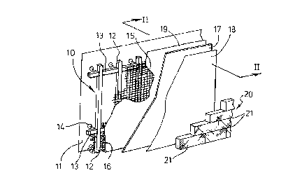
There is disclosed a method of lining a side face (11) of a landfill site
comprising the steps of erecting a framework (10) including laterally spaced
substantially vertically extending members (12) adjacent the surface of the
side face (11), covering the framework (10) with a wire mesh (15), filling the
space between the mesh (15) and the side face (11) with pieces of
substantially inert material (16), laying an impermeable liner (17) over the
wire mesh (15) and constructing a retaining wall (20) over the liner (9),
wherein the vertically extending members (12) are tubular and have spaced
apertures thereto along their lengths.


French Abstract

L'invention concerne un procédé pour revêtir une face (11) latérale d'un site d'enfouissement de déchets, qui comprend les étapes suivantes: ériger un cadre (10) comprenant des éléments (12) qui s'étendent sensiblement verticalement, qui sont espacés latéralement et qui sont adjacents à la surface de la face latérale (11); recouvrir le cadre (10) d'un treillis (15) métallique; remplir l'espace situé entre le treillis (15) et la face (11) latérale avec des morceaux d'un matériau (16) sensiblement inerte; poser un revêtement (17) imperméable sur le treillis (15) métallique et construire une paroi (20) de retenue qui couvre le revêtement (9). Les éléments (12) qui s'étendent verticalement sont tubulaires et ont des orifices espacés sur leur longueur.

Claims

Note: Claims are shown in the official language in which they were submitted.


-6-
CLAIMS
1. A method of lining a side face of a landfill
site comprising the steps of erecting a framework
including laterally spaced substantially vertically
extending members adjacent the surface of the side face,
covering the framework with a wire mesh, filling the
space between the mesh and the side face with pieces of
substantially inert material, laying an impermeable liner
over the wire mesh and constructing a retaining wall over
the liner, wherein the vertically extending members are
tubular and have spaced apertures thereto along their
lengths.
2. A method according to claim 1 wherein the
impermeable liner is sandwiched between layers of
protective geotextile material.
3. A method according to claim 1 or claim 2 wherein
the liner is of high density polyethylene.
4. A method according to any preceding claim
wherein the retaining wall is a gabion wall.
5. A method according to any preceding claim
wherein the framework includes vertically spaced
horizontal members.

-7-
6. A method according to claim 5 wherein cruciform
connecting members are provided at the junctions between
the vertical and horizontal members.
7. A method according to claim 6 wherein the
connecting members are of hollow construction to preserve
a passage through the vertical members over the full
height of the framework.
8. A method according to any preceding claim
wherein the framework carries a track along its upper
edge along which a carriage supporting rolls of
geotextile or liner may run to facilitate deployment of
same.

Description

Note: Descriptions are shown in the official language in which they were submitted.


CA 022~ 6 1998-10-02
WO 97/38174 PCT/(,~,'/~,~842
--1--
LINING FOR A LANDFILL SITE
This invention concerns a lining for a landfill
site.
British Patent No. 2239036 discloses a method of
lining a side face of a landfill site wherein a flexible
impermeable liner is located between inner and outer
walls which are constructed from loosely assembled
pieces of substantially inert material held in position
adjacent to the side face of the site. In a preferred
arrangement the walls are comprised by block-shaped
baskets of wire mesh loosely packed with pieces of stone
or rock and known as "gabions". The patent also
discloses the possibility of incorporating vertically
extending pipes or ducts within the gabion walls for
monitoring gas and leachate at various positions and on
either side of the liner.
The present invention provides a novel method of
lining a side face of a landfill site which enables
monitoring of the integrity of the liner in a
particularly expeditious manner.
According to the present invention there is
provided a method of lining a side face of a landfill
site comprising the steps of erecting a framework
including laterally substantially vertically extending
members adjacent the surface of the side face, covering
the framework with a wire mesh, filling the space
between the mesh and the side face with pieces of
substantially inert material, laying an impormeAble
liner over the wire mesh and constructing a retaining
wall over the liner, wherein the vertically extending

CA 022~ 6 1998-10-02
WO97/38174 PCT/GB96/00842
--2--
members are tubular and have spaced apertures thereto
along their lengths.
The impermeable liner may be sandwiched between
layers of protective geotextile material.
The liner may be of high density polyethylene,
The retaining wall may be a gabion wall.
The framework may carry a track along its upper
edge along which a carriage supporting rolls of
geotextile or liner may run to facilitate deployment of
same.
The invention will be further apparent from the
following description with reference to the several
figures of the accompanying drawings, which show, by way
of example only, one form of lining for a landfill site
embodying the methods of the invention.
Of the drawings:-
Figure l shows a cut-away and exploded
perspective view of part of the
lining;
i
Figure 2 shows a cross-section through the
lining on the line II-II of Figure l;
Fig,ure 3 shows a perspective view of a detail
of the framework of the lining of
Figure 1 on an enlarged scale; and

CA 022~ 6 1998-10-02
WO97/38174 PCTIGB96/00842
--3--
Figure 4 shows how the framework may
incorporate a track along its upper
edge to facilitate construction of
the lining.
It should be understood that the drawings are
diagrammatic only and that in practice the lining might
have considerable height to cover the side faces of a
disused quarry for example.
Referring firstly to Figures l and 2 it will be
seen that the lining is comprised by a framework lO
lying in a substantially vertical plane as closely
adjacent the side face ll of a disused quarry as
possible having regard to the irregularities of such
side face.
The framework lO comprises vertical members 12
of box-section and horizontal members 13 also of
box-section, and is secured by rockbolts 14.
The framework lO is covered by a wire mesh 15
and the space between the mesh 15 and the face ll is
loosely filled with pieces 16 of stone and rock sized
from S to lO centimetres upwards.
The mesh 15 is covered by an impervious liner 17
of high density polyethylene sandwiched betweeen inner
and outer protective layers 18 and l9 of geotextile.
The liner 17 is held in position by a retaining
wall 20 constructed from gabions 21, which is to say
block-shaped baskets of wire mesh filled with pieces of
stone and rock.

CA 022~ 6 1998-10-02
WO 97/3gl74 PCT/GB96/00842
--4-- _
Turning now to Figure 3, it will be seen that
the junctions between the vertical and horizontal
members 12 and 13 of the framework 10 are provided by
cruciform connecting members 30, which are themselves of
hollow contruction to preserve a passage through the
vertical members 12 over the full height of the
framework 10.
Apertures 22 are provided in the sides of the
members 12 at spaced intervals along their lengths.
Typically the members 12 will be spaced apart by
l.Sm and since they lie on the outside (i.e. quarry face
side) of the liner 17, the integrity of the liner can be
closely monitored by instruments analysing any gas or
leachate present withir. the members 12. Such
instruments may provide continuous monitoring or may be
deployed (for example lowered through the members 12) as
required. Narrow bore pipes (of plastics for example)
may be installed through the members 10 to enable
leachate to be pumped to the surface for analysis.
When any fault in the liner 17 might be detected
the possibility of repair by pumping a sealant such as a
cementitious grout to the damaged site through the
nearest members 12 is present.
Referring now to Figure 4 it can be seen how the
framework 10 might support a monorail track 40 along its
upper edge to carry machines supporting rolls 41 of
liner or geotextile to facilitate their installation.

CA 022~ 6 1998-10-02
WO97/38174 PCT/GB96/00842
--5--
It will be appreciated that it is not intended
~ to limit the invention to the above example only, many
variations, such as might readily occur to one skilled
in the art, being possible, without departing from the
scope thereof.
Thus for example, the apertures to the interior
of the vertical members might be provided only by
unsealed joints at the members 30 or by apertures in the
members 30 themselves.
Again, for example, a Bentonite or similar
membrane may be included in juxtaposition with the
impermeable liner.

Representative Drawing
A single figure which represents the drawing illustrating the invention.
Administrative Status

2024-08-01:As part of the Next Generation Patents (NGP) transition, the Canadian Patents Database (CPD) now contains a more detailed Event History, which replicates the Event Log of our new back-office solution.

Please note that "Inactive:" events refers to events no longer in use in our new back-office solution.

For a clearer understanding of the status of the application/patent presented on this page, the site Disclaimer , as well as the definitions for Patent , Event History , Maintenance Fee  and Payment History  should be consulted.

Event History

Description Date
Application Not Reinstated by Deadline 2003-04-07
Time Limit for Reversal Expired 2003-04-07
Deemed Abandoned - Failure to Respond to Maintenance Fee Notice 2002-04-08
Letter Sent 2000-10-17
Reinstatement Requirements Deemed Compliant for All Abandonment Reasons 2000-09-29
Deemed Abandoned - Failure to Respond to Maintenance Fee Notice 2000-04-06
Inactive: Single transfer 1999-03-09
Inactive: Courtesy letter - Evidence 1999-03-09
Inactive: Single transfer 1999-01-22
Classification Modified 1998-12-17
Inactive: IPC assigned 1998-12-17
Inactive: First IPC assigned 1998-12-17
Inactive: IPC assigned 1998-12-17
Inactive: Courtesy letter - Evidence 1998-12-08
Inactive: Notice - National entry - No RFE 1998-12-03
Application Received - PCT 1998-12-01
Application Published (Open to Public Inspection) 1997-10-16

Abandonment History

Abandonment Date Reason Reinstatement Date
2002-04-08
2000-04-06

Maintenance Fee

The last payment was received on 2001-03-21

Note : If the full payment has not been received on or before the date indicated, a further fee may be required which may be one of the following

  • the reinstatement fee;
  • the late payment fee; or
  • additional fee to reverse deemed expiry.

Patent fees are adjusted on the 1st of January every year. The amounts above are the current amounts if received by December 31 of the current year.
Please refer to the CIPO Patent Fees web page to see all current fee amounts.

Fee History

Fee Type Anniversary Year Due Date Paid Date
Basic national fee - standard 1998-10-02
MF (application, 2nd anniv.) - standard 02 1998-04-06 1998-10-02
Registration of a document 1999-01-22
MF (application, 3rd anniv.) - standard 03 1999-04-06 1999-02-18
Registration of a document 1999-03-09
Reinstatement 2000-09-29
MF (application, 4th anniv.) - standard 04 2000-04-06 2000-09-29
MF (application, 5th anniv.) - standard 05 2001-04-06 2001-03-21
Owners on Record

Note: Records showing the ownership history in alphabetical order.

Current Owners on Record
HANSON QUARRY PRODUCTS EUROPE LIMITED
Past Owners on Record
IAN MICHAEL SPENCER
MICHAEL LEONARD DAVIES
Past Owners that do not appear in the "Owners on Record" listing will appear in other documentation within the application.
Documents

To view selected files, please enter reCAPTCHA code :


To view images, click a link in the Document Description column (Temporarily unavailable). To download the documents, select one or more checkboxes in the first column and then click the "Download Selected in PDF format (Zip Archive)" or the "Download Selected as Single PDF" button.

List of published and non-published patent-specific documents on the CPD .

If you have any difficulty accessing content, you can call the Client Service Centre at 1-866-997-1936 or send them an e-mail at CIPO Client Service Centre.

({010=All Documents, 020=As Filed, 030=As Open to Public Inspection, 040=At Issuance, 050=Examination, 060=Incoming Correspondence, 070=Miscellaneous, 080=Outgoing Correspondence, 090=Payment})


Document
Description 
Date
(yyyy-mm-dd) 
Number of pages   Size of Image (KB) 
Representative drawing 1999-01-25 1 10
Abstract 1998-10-01 1 57
Description 1998-10-01 5 149
Drawings 1998-10-01 2 48
Claims 1998-10-01 2 49
Notice of National Entry 1998-12-02 1 192
Courtesy - Certificate of registration (related document(s)) 1999-04-18 1 117
Courtesy - Abandonment Letter (Maintenance Fee) 2000-05-03 1 183
Notice of Reinstatement 2000-10-16 1 171
Courtesy - Abandonment Letter (Maintenance Fee) 2002-05-05 1 183
Reminder - Request for Examination 2002-12-08 1 113
PCT 1998-10-01 9 273
Correspondence 1998-12-07 1 30
Correspondence 1999-03-08 2 15
Fees 1999-02-17 1 47