Note: Descriptions are shown in the official language in which they were submitted.
CA 02251158 1998-10-19
AGRICULTURAL FEED MIXER BLADE
FIELD OF THE INVENTION:
This invention relates to cutting tools and more particularly pertains to a
new
agricultural feed mixer blade for providing a mixer blade with improved impact
and
wear resistance.
DESCRIPTION OF THE PRIOR ART:
The use of cutting tools is known in the prior art. More specifically, cutting
tools heretofore devised and utilized are known to consist basically of
familiar,
expected and obvious structural configurations, notwithstanding the myriad of
designs encompassed by the crowded prior art which have been developed for the
fulfilment of countless objectives and requirements.
Known prior art cutting tools include United States patent No. 4,205,564;
United States patent No. 4,690,024; United States patent No. 4,770,253; United
States patent No. 5,074,623; United States patent No. 5,193,280; United States
patent No. 5,331,876; United States patent No. 5,351,595; and United States
patent
No. 5,427,000.
While these devices fulfil their respective, particular objectives and
requirements, the aforementioned patents do not disclose a new agricultural
feed
mixer blade. The inventive device includes a plate having a leading edge with
a
plurality of teeth arranged in a stepped contiguous relationship therealong,
and an
elongated cutting element affixed to a face edge of each of the teeth wherein
the
cutting element is formed of a substance harder than that of the plate such as
a
cemented carbide.
In these respects, the agricultural feed mixer blade according to the present
invention substantially departs from the conventional concepts and designs of
the
1
CA 02251158 1998-10-19
prior art, and in so doing provides an apparatus primarily developed for the
purpose
of providing a mixer blade with improved impact and wear resistance.
SUMMARY OF THE INVENTION:
In view of the foregoing disadvantages inherent in the known types of
cutting tools now present in the prior art, the present invention provides a
new
agricultural feed mixer blade construction wherein the same can be utilized
for
providing a mixer blade with improved impact and wear resistance.
The general purpose of the present invention, which will be described
subsequently in greater detail, is to provide a new agricultural feed mixer
blade
apparatus and method which has many of the advantages of the cutting tools
mentioned heretofore and many novel features that result in a new agricultural
feed
mixer blade which is not anticipated, rendered obvious, suggested, or even
implied
by any of the prior art cutting tools, either alone or in any combination
thereof.
To attain this, the present invention generally comprises a plate having a
leading edge with a plurality of teeth arranged in a stepped contiguous
relationship
therealong, and an elongated cutting element affixed to a face edge of each of
the
teeth wherein the cutting element is formed of a substance harder than that of
the
plate such as a cemented carbide.
There has thus been outlined, rather broadly, the more important features of
the invention in order that the detailed description thereof that follows may
be better
understood, and in order that the present contribution to the art may be
better
appreciated. There are additional features of the invention that will be
described
hereinafter and which will form the subject matter of the claims appended
hereto.
In this respect, before explaining at least one embodiment of the invention
in detail, it is to be understood that the invention is not limited in its
application to
the details of construction and to the arrangements of the components set
forth in
the following description or illustrated in the drawings. The invention is
capable
2
CA 02251158 1998-10-19
of other embodiments and of being practised and carried out in various ways.
Also,
it is to be understood that the phraseology and terminology employed herein
are for
the purpose of description and should not be regarded as limiting.
As such, those skilled in the art will appreciate that the conception, upon
which this disclosure is based, may readily be utilized as a basis for the
designing
of other structures, methods and systems for carrying out the several purposes
of the
present invention. It is important, therefore, that the claims be regarded as
including
such equivalent constructions insofar as they do not depart from the spirit
and scope
of the present invention.
Further, the purpose of the foregoing abstract is to enable the United States
Patent Office and the public generally, and especially the scientists,
engineers and
practitioners in the art who are not familiar with patent or legal terms or
phraseology, to determine quickly from a cursory inspection the nature and
essence
of the technical disclosure of the application. The abstract is neither
intended to
define the invention of the application, which is measured by the claims, nor
is it
intended to be limiting as to the scope of the invention in any way.
It is therefore an object of the present invention to provide a new
agricultural
feed mixer blade apparatus and method which has many of the advantages of the
cutting tools mentioned heretofore and many novel features that result in a
new
agricultural feed mixer blade which is not anticipated, rendered obvious,
suggested,
or even implied by any of the prior art cutting tools, either alone or in any
combination thereof.
It is another object of the present invention to provide a new agricultural
feed mixer blade which may be easily and efficiently manufactured and
marketed.
It is a further object of the present invention to provide a new agricultural
feed mixer blade which is of a durable and reliable construction.
An even further object of the present invention is to provide a new
agricultural feed mixer blade which is susceptible of a low cost of
manufacture with
3
CA 02251158 1998-10-19
regard to both materials and labour, and which accordingly is then susceptible
of
low prices of sale to the consuming public, thereby making such agricultural
feed
mixer blade economically available to the buying public.
Still yet another object of the present invention is to provide a new
agricultural feed mixer blade which provides in the apparatuses and methods of
the
prior art some of the advantages thereof, while simultaneously overcoming some
of
the disadvantages normally associated therewith.
Still another object of the present invention is to provide a new agricultural
feed mixer blade for providing a mixer blade with improved impact and wear
resistance.
Yet another object of the present invention is to provide a new agricultural
feed mixer blade which includes a plate having a leading edge with a plurality
of
teeth arranged in a stepped contiguous relationship therealong, and an
elongated
cutting element affixed to a face edge of each of the teeth wherein the
cutting
element is formed of a substance harder than that of the plate such as a
cemented
carbide.
Still yet another object of the present invention is to provide a new
agricultural feed mixer blade that has a prolonged life. Mixer blades made of
steel
have the advantage of being relatively inexpensive, but also the disadvantage
of
wearing out extremely rapidly. Accordingly, once worn out, the steel blades
must
be replaced which, in addition to being time consuming, also results in down-
time
for the equipment. Thus, the present invention provides a mixer blade with an
improved life span which, as a result, reduces the occurrence of such
replacement
and eliminates the associated problems.
Even still another object of the present invention is to provide a new
agricultural feed mixer blade that is adapted to more adequately address the
harsh
conditions often encountered during the mixing of agricultural feed including,
more
specifically, low revolution mixing (1 to 40 RPM range).
4
CA 02251158 1998-10-19
BRIEF DESCRIPTION OF THE DRAWINGS:
The novel features which are believed to be characteristic of the present
invention, as to its structure, organization, use and method of operation,
together
with further objectives and advantages thereof, will be better understood from
the
following drawings in which a presently preferred embodiment of the invention
will
now be illustrated by way of example. It is expressly understood, however,
that the
drawings are for the purpose of illustration and description only and are not
intended as a definition of the limits of the invention. Embodiments of this
invention will now be described by way of example in association with the
accompanying drawings in which:
Figure 1 is a an illustration of an agricultural feed mixer establishing one
environment of use of a new agricultural feed mixer blade according to the
present
invention;
Figure 2 is a top view of the mixing bin and the auger of the agricultural
feed mixer with a plurality of agricultural feed mixer blades mounted on the
auger
according to the present invention;
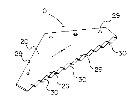
Figure 3 is perspective illustration of the present invention;
Figure 4 is a top view of the present invention;
Figure 5 is a cross sectional view taken along line 5-5 of Figure 3;
Figure 6 is a view similar to Figure 5 illustrating an optional embodiment of
the cutting element of the present invention;
Figure 7 is a top view of a first optional embodiment of the present
invention;
Figure 8 is a top view of a second optional embodiment of the present
invention;
5
CA 02251158 1998-10-19
DETAILED DESCRIPTION OF THE PREFERRED EMBODIMENTS:
Reference will now be made to Figures 1 through 8 in which a new
agricultural feed mixer blade embodying the principles and concepts of the
present
invention and generally designated by the reference numeral 10 will be
described.
As best illustrated in Figures 1 through 8, the agricultural feed mixer blade
comprises a plate 20 having a leading edge 21 with a plurality of teeth 26
arranged in a stepped contiguous relationship therealong, and an elongated
cutting
element 30 affixed to a face edge 27 of each of the teeth 26 wherein the
cutting
element 30 is formed of a substance harder than that of the plate 20 such as a
10 cemented carbide.
As best illustrated in Figures 1 and 2, the agricultural feed mixer blade 10
of the present invention is intended for use in an agricultural feed mixer 2.
The
agricultural feed mixer 2 includes a mixing bin 3 with a tapered auger 4
rotatably
mounted therein. Accordingly, a plurality of blades 10 are secured to the
auger 4
in spaced relation over the length thereof. The plurality of blades 10 are
mounted
so as to protrude beyond the periphery of the auger 4. As such, the plurality
of
blades 10 and the auger 4 cut and mix agricultural feed placed in the mixing
bin 3
including, more specifically, hay rations. Although the agricultural feed
mixer 2
illustrated in the drawings is of the vertical auger-type, it is understood
that the
present invention may also be incorporated into the design of horizontal auger-
type
agricultural feed mixers.
The plate 20 is substantially planar and formed of steel. In the preferred
embodiment, best illustrated in Figures 3 through 6, the plate 20 is generally
triangular in shape. As such, the plate 20 has a leading edge 21, a first rear
edge
22, and a second rear edge 23. Accordingly, the first rear edge 22 is oriented
at a
first angle A relative to the leading edge 21 and the second rear edge 23 is
oriented
at a second angle B relative to the first rear edge 22. The leading edge 21 of
the
plate 20 has an innermost end 21a and an outermost end 21b. Accordingly, a
heel
6
CA 02251158 1998-10-19
edge 24 is provided at an intersection of the first rear edge 22 and the
innermost
end 21 a of the leading edge 21. In addition, a toe edge 25 is provided at an
intersection of the second rear edge 23 and the outermost end 21b of the
leading
edge 21.
In an illustrative embodiment, the leading edge 21 of the plate 20 is about
17 inches long, the first rear edge 22 is about 8 inches long, and the second
rear
edge 23 is about 12 inches long. In addition, the first angle A is about 35
degrees
and the second angle B is about 62 degrees. Furthermore, the heel edge 24 is
oriented at an angle of about 80 degrees relative to the leading edge 21 and
the toe
edge 25 is generally perpendicularly oriented to the leading edge 21. In the
illustrative embodiment, the plate 20 has a thickness of about 3/8 inch.
The leading edge 21 of the plate 20, as illustrated in Figures 3 and 4, is
generally straight. However, as illustrated in Figures 7 and 8, the leading
edge 21
of the plate 20 may also be generally convex or saliently angled. The
saliently
angled leading edge includes two edges oriented at an obtuse angle wherein the
apex of the angle faces outward. Accordingly, the description herein generally
applies to all embodiments of the leading edge 21.
The plurality of teeth 26 are arranged in a stepped contiguous relationship
along the leading edge 21 of the plate 20. Each of the teeth 26 include a face
edge
27 and a back edge 28. As such, the back edge 28 of a first tooth is
contiguous
with the face edge 27 of a second adjacent tooth. Accordingly, the back edge
28
of a first tooth and the face edge 27 of a second adjacent tooth form a
triangular
gullet between adjacent teeth 26. The face edge 27 of each of the teeth 26 are
oriented at an angle C relative to the leading edge 21 of the plate 20. The
angle of
orientation (angle C) of the teeth 26 varies according to the application so
as to
maximize the effective cutting edge of the blade 10. Preferably, the angle C
is in
the range of about 10 degrees to about 30 degrees. Most preferably, however,
the
angle C is in the range of about 15 degrees to about 25 degrees. In an
illustrative
7
CA 02251158 1998-10-19
embodiment, the angle C is about 19 degrees. Furthermore, the back edge 28 of
a
first tooth is generally perpendicularly oriented to the face edge 27 of a
second
adjacent tooth.
The plate 20 has a plurality of mounting holes 29 formed therein. The
mounting holes 29 permit mounting of the blade 10 to the auger 4 of the
agricultural feed mixer 2. In an illustrative embodiment, a set of three
mounting
holes 29 are provided in spaced relation along the first rear edge 22 of the
plate 20.
In addition, a single mounting hole 29 is provided along the second rear edge
23
towards the toe edge 25 of the plate 20.
In the preferred embodiment, each of the cutting elements 30 are formed of
a cemented carbide material. Preferably, the cemented carbide material has a
low
cobalt content thereby increasing hardness and wear resistance. Most
preferably,
the cobalt content is in the range of about 2 to about 13 percent. In an
illustrative
embodiment, the composition of the cemented carbide material by weight is
about
90 percent tungsten carbide and about 10 percent cobalt.
In a first embodiment, each of the cutting elements 30 has a generally
triangular profile (Figure 7). As such, each of the cutting elements 30 has a
rear
surface 31, an angled top surface 32, and an angled bottom surface 33 wherein
the
angled top surface 32 and the angled bottom surface 33 converge to form a
cutting
edge 34. Furthermore, each of the cutting elements 30 has a pair of end
surfaces
35. Each of the cutting elements 30 has a top chamfer 36 provided along an
intersection of the angled top surface 32 and the rear surface 31 and has a
bottom
chamfer 37 provided along an intersection of the angled bottom surface 33 and
the
rear surface 31. In addition, an end chamfer (not shown) is provided along an
intersection of each of the end surfaces 35 and the rear surface 31.
In a second embodiment, each of the cutting elements 130 has a generally
wedge-shaped profile (Figure 8). As such, each of the cutting elements 130 has
a
rear surface 131, an angled top surface 132, and a bottom surface 133 wherein
the
8
CA 02251158 1998-10-19
angled top surface 132 intersects the bottom surface 133 to form a cutting
edge 134.
Furthermore, each of the cutting elements 130 has a pair of end surfaces 135.
Each
of the cutting elements 130 has a top chamfer 136 provided along an
intersection
of the angled top surface 132 and the rear surface 131 and has a bottom
chamfer
137 provided along an intersection of the bottom surface 133 and the rear
surface
131. In addition, an end chamfer (not shown) is provided along an intersection
of
each of the end surfaces 135 and the rear surface 131.
Each of the cutting elements 30 are secured to the teeth 26 by brazing. The
cutting elements 30 are of a length generally equal to that of the face edge
27 of the
teeth 26. As such, the rear surface 31 and one of the end surfaces 35 of each
of the
cutting elements 30 are brazed to the face edge 27 and the back edge 28,
respectively, of adjacent teeth. In the preferred embodiment, the face edge 27
of
each of the teeth 26 is of a length substantially greater than that of the
back edge
28. Accordingly, in an illustrative embodiment, the face edge 27 of each of
the
teeth 26 is about 1.3 inches and the back edge 28 is about 0.5 inches. As
such, the
cutting edge 34 of each of the cutting elements 30 is about 1.3 inches. In
addition,
the thickness of each of the cutting elements 30 is generally equal to the
thickness
of the plate 20. As such, the height of the rear surface 31 of the cutting
element 30
is generally equal to the thickness of the plate 20. Accordingly, in an
illustrative
embodiment, the height of the rear surface 31 of the cutting element 30 is 3/8
inch.
In use, a plurality of blades 10 are mounted on the auger 4 of the
agricultural
feed mixer 2 in spaced relation over the length of the auger 4. The blades 10
are
mounted on the auger 4 such that the leading edge 21 of the plate 20
substantially
protrudes beyond the periphery of the auger 4. Agricultural feed desired to be
mixed is placed within the mixing bin 3 whereby the plurality of blades 10 and
the
auger 4 cut and mix the agricultural feed.
As to a further discussion of the manner of usage and operation of the
present invention, the same should be apparent from the above description.
9
CA 02251158 1998-10-19
Accordingly, no further discussion relating to the manner of usage and
operation
will be provided.
With respect to the above description then, it is to be realized that the
optimum dimensional relationships for the parts of the invention, to include
variations in size, materials, shape, form, function and manner of operation,
assembly and use, are deemed readily apparent and obvious to one skilled in
the art,
and all equivalent relationships to those illustrated in the drawings and
described in
the specification are intended to be encompassed by the present invention.
Therefore, the foregoing is considered as illustrative only of the principles
of the invention. Further, since numerous modifications and changes will
readily
occur to those skilled in the art, it is not desired to limit the invention to
the exact
construction and operation shown and described, and accordingly, all suitable
modifications and equivalents may be resorted to, falling within the scope of
the
invention.
Other modifications and alterations may be used in the design and
manufacture of the apparatus of the present invention without departing from
the
spirit and scope of the accompanying claims.
Throughout this specification and the claims which follow, unless the context
requires otherwise, the word "comprise", and variations such as "comprises" or
"comprising", will be understood to imply the inclusion of a stated integer or
step
or group of integers or steps but not to the exclusion of any other integer or
step or
group of integers or steps.