Note: Descriptions are shown in the official language in which they were submitted.
CA 022~1209 1998-10-22
Atty. Docket No.: 73948-185
A COMOLDED SCREW-TOP/FLIP-TOP LID ASSEMBLY
FIELD OF THE INVENTION
The present invention relates generally to a
container system. More particularly, the present
invention relates to a screw-top/flip-top lid assembly
for use in storage applications.
BACKGROUND OF THE INVENTION
Conventional screw-top/flip-top lids are
utilized to cover a container that has a threaded
opening. The lids typically consist of three components:
the screw cap, the flip cap, and a gasket. Generally,
the screw cap of the screw-top/flip-top lid threadably
engages the container opening, and the flip cap opens and
closes about a hinge that is coupled to the flip cap and
to the screw cap. The flip cap allows easy access to the
container opening once the screw cap is attached.
The gasket included in conventional screw-
top/flip-top lids is hand-assembled onto either the screw
cap or the flip cap. This configuration provides a seal
between the screw cap-flip cap interface, the screw cap-
container interface, or both. However, this is generally
not a stable seal because the gasket remains mobile on
the screw cap or on the flip cap. Not surprisingly, the
gasket can even fall off completely.
Additionally, conventional screw-top/flip-top
lid assemblies require three separate pieces. The
production and the assembly of three separate pieces
CA 022~1209 1998-10-22
result in increased assembly time and manufactur-ng
costs. In particular, a gasket must be formea in a
separate molding process that is distinct from the
molding of the screw cap and the flip cap. Moreover, the
additional step of hand-assembling the gasket onto the
flip cap or the screw cap is labor-intensive, which
further increases production costs. Even post-production
costs are increased, since there are at least three
pieces to inventory for the conventional screw-top/flip-
top lid.
The screw caps of most conventional screw-
top/flip-top lids generally have a smooth plastic surface
that can be difficult to handle when screwing the lid
either onto or off a container opening. Some screw caps
currently include hand grips made of hardened plastic.
Nonetheless, these plastic grips often do not provide
adequate traction for obtaining a firm hold.
Thus, there is a need for a low-cost screw-
top/flip-top lid assembly. Further, there is a need for
a screw-top/flip-top lid with rubber-like grips that
enable a firmer hold of the plastic screw cap when
screwing the lid either onto or off a container opening.
Further still, there is a need for a manufacturing method
by which to produce a screw-top/flip-top lid with a
reduced parts count, thereby minimizing production and
inventory costs.
SUMMARY OF INVENTION
The present invention relates to a lid assembly
for attaching to a container having a threaded container
opening. The lid assembly includes a first member and a
second member. The first member is configured to
threadably engage the threaded container opening. The
first member is comprised of plastic and includes a
comolded gasket. The second member is coupled to the
first member by a hinge. The second member engages the
comolded gasket when in a closed position.
CA 022~1209 1998-10-22
The present lnvention further relates to a
screw/flip-top lid that includes a plastic base and a
flip cover. The plastic base has a base opening that :s
defined by a rim. The rim has a top surface that is at
least partially covered by a comolded gasket. The flip
cover is coupled to the plastic base and engages the
comoided gasket when in a closed position.
The present invention still further relates t3
a method of manufacturing a lid assembly. The method
includes molding a flip-top cover and a base that has an
opening. The method further includes coinjection molding
a gasket about a periphery of the opening.
According to one exemplary aspect of the
present invention, the lid assembly is a screw/flip-top
lid that includes a plastic base coupled to a plastic
flip cover and a rubber-like gasket. The gasket is
comolded about the top surface of the base. The gasket
provides a seal between the plastic base and a
corresponding container. When the lid assembly is in the
closed position, the flip cover engages the comolded
gasket on the plastic base, thereby providing an
additional seal along the flip cover-plastic base
interface of the lid assembly.
According to another exemplary aspect of the
present invention, part of the comolded rubber-like
plastic extends vertically downward from the exterior of
the bottom surface of the gasket, forming hand grips
along the exterior surface of the plastic base. The
grips allow for a firmer hold of the plastic base when
screwing the lid assembly either onto or off a container
opening.
According to yet another exemplary aspect of
the present invention, the method of manufacturing the
lid assembly utilizes two-shot molding technology,
thereby allowing for two different types of materials to
be molded in one part. The two comolded materials can be
polypropylene (e.g., the plastic flip-top cover and base)
and a thermal plastic elastomer (e.g., the rubber-like
CA 022~1209 1998-10-22
gasket and grips). The comolded materials can be of
different colors, which aads to the decorative
versatility of the lid assembly. This process
advantageously eliminates the labor-intensive need to
hand-assemble a gasket piece onto the plastic base. As a
result, manufacturing costs are lowered since fewer
separate parts are required and less assembly is
involved. Moreover, post-production cost is also
~ minimized since there are fewer parts to inventory.
BRIEF DESCRIPTION OF THE DRAWINGS
The invention will be described with further
reference to the accompanying drawings, wherein like
numerals denote like elements:
Figure 1 is a perspective view of a screw-
top/flip-top lid assembly attached to a container, with
the flip cap in a closed configuration, in accordance
with an exemplary embodiment of the present invention;
Figure 2 is a top view of the flip cap used in
the screw-top/flip-top lid assembly illustrated in
Figure l;
Figure 3 is a perspective view of the screw cap
of the screw-top/flip-top lid assembly illustrated in
Figure 1, including hand grips and a comolded gasket;
Figure 4 is a partial bottom view of the screw
cap illustrated in Figure 3;
Figure 5 is a perspective view of the gasket
and hand grips that are comolded with the screw cap
illustrated in Figures 3 and 4;
Figure 6 is a side view of the screw-top/flip-
top lid assembly illustrated in Figure 1, with a partial
cross-sectional view showing the gasket disposed between
the screw cap and the flip cap; and
Figure 7 is a side view of the screw-top/flip-
top lid assembly illustrated in Figure 1, showing partial
cross-sectional views of a clasp area and of a hinge
area.
CA 022~1209 1998-10-22
DETAILED DESCRIPTION
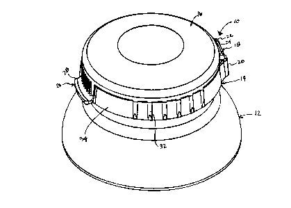
With reference to Figure 1, a lid assembly 10
is shown attached to a container 12 which has a threaded
opening (Figures 6 and 7). Lid assembly 10 is preferably
a screw-top/flip-top lid that includes a base or a screw
cap 14 pivotally coupled to a flip cover or a flip cap 16
by a hinge 18. Hinge 18 of lid assembly 10 includes a
pair of bearing members 20 and 22 (Figures 3 and 4)
~ disposed on screw cap 14 and a rod member 24 (Figure 2)
disposed on flip cap 16. Lid assembly 10 further
includes a fastener or a clasp 26 that engages screw
cap 14 when lid assembly 10 is in a closed configuration,
as shown in Figure 1. In particular, clasp 26 includes
an elongated tab member 28 disposed on flip cap 16 and a
receiving area 30 disposed on screw cap 14 of lid
assembly 10 (Figures 3 and 7).
Screw cap 14 of lid assembly 10 further
includes vertical grips 32 disposed on an exterior
surface 34. Screw cap 14 is preferably configured to
threadably engage (e.g., screw onto) the opening of
container 12 (Figures 3 and 4). Both screw cap 14 and
flip cap 16 of lid assembly 10 are preferably made of a
plastic, such as, polypropylene, whereas container 12 can
be made of plastic, glass, metal, or other material.
. A top view of flip cap 16 of lid assembly 10 is
shown in Figure 2, including rod member 24 of hinge 18
and elongated tab member 28 of clasp 26. Member 24 of
hinge 18 includes rod ends 36. Rod ends 36 are disposed
within a corresponding slot 38 (Figures 3 and 4) on each
of bearing members 20 and 22 of hinge 18 on screw cap 14
of lid assembly 10. In particular, each slot 38 on each
of members 20 and 22 ends with a round terminus 40.
Round terminus 40 on each of first members 20 and 22 of
screw cap 14 is appropriately sized to fit and to
maintain rod ends 36 on member 24 of hinge 18 on flip cap
16 (e.g., ends 36 snap fit into slots 38). In
particular, hinge 18 allows flip cap 16 of lid
assembly 10 to pivot or to flip either away or toward
CA 022~l209 l998-l0-22
screw cap 14 when either opening or closing,
respectively, lid assembly 10. Round terminus 40 of
slot 38 in one of members 20 and 22 of hinge 18 iS
partially visible in Figure 3, while each slot 38 on each
of members 20 and 22 iS shown in Figure 4.
Figures 3 and 4 further illustrate screw cap 14
of lid assembly 10. Screw cap 14 has an opening 44
defined by a periphery or rim 46, and a gasket 48. Area
30 of clasp 26 includes a ridge 50. Grooves 42 are
circumferentially disposed on an internal surface 52 of
screw cap 14 to engage a plurality of threads 54 disposed
on an external surface 56 of a rim 58 on container 12
(Figures 6 and 7).
Rim 46, which defines screw cap opening 44, has
a top surface 60 (Figure 7), an interior surface 62, and
a bottom surface 64. Gasket 48 iS disposed about the
periphery of screw cap opening 44. In particular,
gasket 48 of screw cap 14 includes a short member 68 and
an elongated member 70 (Figures 6 and 7), which define a
groove 66. Groove 66 on gasket 48 iS preferably
circumferentially disposed about rim 46 of screw cap 14.
Gasket 48 preferably covers at least portions of top
surface 60 and interior surface 62 of rim 46 on screw
cap 14. Furthermore, portions of gasket 48 extend beyond
top surface 60 of rim 46 and meld into vertical grips 32.
Grips 32 preferably extend the height of screw cap 14 and
are spaced at regular intervals from each other along
exterior surface 34 of screw cap 14.
With reference to Figure 5, a perspective view
of gasket 48 and grips 32 iS shown. Grips 32 are
configured to be vertical ribs that are integral with
gasket 48 of screw cap 14. Gasket 48 and grips 32 are
preferably made of a rubber-like thermal plastic
elastomer (TPE) that is comolded with plastic screw cap
14 of lid assembly 10. Rubber-like grips 32 allow for a
firmer hold of plastic screw cap 14 when screwing lid
assembly 10 either onto or off the threaded opening of
container 12.
CA 022~1209 1998-10-22
Coinjection molding (also called comolding,
sandwlch construction, ~wo-shot, double-shot injection,
multiple-shot injection, two-color molding, inmolding,
and so forth) generally refers to laminating or disposing
two or more different plastics together to take advantage
of the different properties contributed by each type.
The comolding process is not limited to different plastic
types only: differently-colored material made of the
~ same plastic can also be comolded. Different plastics
that are comolded in the same process usually have
similar physical properties, such as, melting point.
Furthermore, the comolding process typically involves two
or more injection units, one for each plastic type (or
color, if using the same plastic type).
In particular, the method for manufacturing lid
assembly 10 allows for two different types of materials
to be comolded in one part. In one preferred embodiment,
the two comolded materials are a polypropylene plastic
(e.g., flip cap 16 and screw cap 14) and a thermal
plastic elastomer (e.g., rubber-like gasket 48 and grips
32). More specifically, the method for manufacturing lid
assembly 10 comprises molding screw cap 14 (Figures 1 and
3) and flip cap 16 (Figures 1 and 2) from the
polypropylene plastic and coinjection molding gasket 48
and grips 32 from the thermal plastic elastomer about the
periphery of screw cap opening 44 and on exterior surface
34 of screw cap 14, respectively (Figure 3). Preferably,
screw cap 14 is formed in a mold, followed by the
formation of gasket 48 in the same mold around screw
cap 14. Alternatively, the molding process can be
conducted in reverse sequence, e.g., gasket 48 is first
formed in a mold, followed by the formation of screw
cap 14 in the same mold.
The comolding process used in the manufacturing
of lid assembly 10 also adds decorative versatility to
the screw-top/flip-top lid, since the polypropylene
plastic and the thermal plastic elastomer can be of
different colors. Color-matching schemes can be used for
CA 022~1209 1998-10-22
seasonal or holiday themes. For example, a Halloween
motif can be achieved by using an orange-colored
polypropylene plastic (e.g., screw cap 14 and flip cap
16) with a black-colored thermal plastic elastomer (e.g.,
gasket 48 and grips 32). Even sports enthusiasts can
enjoy color combinations representative of their favorite
professional sports team.
Wlth reference to Figure 6, a side view of lid
- assembly 10 is shown. In particular, lid assembly 10 is
shown attached to container 12. More specifically, to
attach lid assembly 10 to container 12, grooves 42 on
internal surface 52 of screw cap 14 (Figure 3)
complementarily engage threads 54 circumferentially
disposed on external surface 56 of rim 58 on container 12
(also shown in Figure 7). A ridge 72, also disposed on
external surface 56, limits the extent to which screw cap
14 of lid assembly 10 engages rim 58 of container 12.
Figure 6 also shows a partial cross-sectional
view of lid assembly 10 in a closed configuration,
wherein gasket 48 is disposed between screw cap 14 and
flip cap 16. In the closed configuration of lid
assembly 10, flip cap 16 covers screw cap opening 44
(Figure 3). In a cross-sectional view, gasket 48
generally appears in an inverted L-shaped configuration,
where elongated member 70 extends along interior
surface 62 and beyond bottom surface 64 of rim 46 on
screw cap 14 and where short member 68 extends along top
surface 60 of rim 46. Elongated member 70 of gasket 68
includes a first end 74, a second end 76, and a
midportion 78.
When lid assembly 10 is in the closed
configuration, first end 74 on elongated member 70 of
gasket 48 on screw cap 14 is engaged by, and in contact
with, flip cap 16. In contrast, second end 76 on
elongated member 70 of gasket 48 is freely
circumferentially disposed along an internal surface 80
of rim 58 of container 12. Midportion 78 on elongated
member 70 of gasket 48 simultaneously engages interior
CA 022~1209 1998-10-22
surface 62 of rim 46 on screw cap 14 and a superior
portion of internal surface 80 of rim 58 on container 12,
thereby effec~ing a seal along the interface between
screw cap 14 of lid assembly 10 and rim 58 of
container 12. Moreover, when lid assembly 10 is still in
the closed configuration, ridge 82 of short member 68 on
gasket 48 is preferably disposed between a bottom portion
of flip cap 16 and top surface 60 of rim 46 on screw
- cap 14, thereby effecting a seal along the interface
between screw cap 14 and flip cap 16 of lid assembly 10.
With reference to Figure 7, a side view of lid
assembly 10 in the closed configuration, while attached
to container 12, is shown. Grips 32 on exterior
surface 34 of screw cap 14 are prominently featured.
Similar to Figure 6, Figure 7 also includes a partial
cross-sectional view of lid assembly 10 in the closed
configuration. However, Figure 7 demonstrates a section
of lid assembly 10 that includes hinge 18. In
particular, rod ends 36 on member 24 of hinge 18 is shown
disposed within round terminus 40 at the end of slot 38
on one of members 20 and 22.
Figure 7 further includes a partial cross-
sectional view of a portion of lid assembly 10 that
includes clasp 26. In particular, Figure 7 illustrates
that clasp 26 includes elongated tab member 28 disposed
on flip cap 16 and receiving area 30 disposed on screw
cap 14 of lid assembly 10. Elongated tab member 28 of
clasp 26 melds into or is contiguous with an outwardly-
extending lifting flange 88. Lifting flange 88 includes
an indentation 90 disposed on the interior aspect of
elongated tab member 28, facing area 30 of clasp 26.
Indentation 90 on tab member 28 of clasp 26 is preferably
sized to receive a ridge 92 disposed on area 30 to secure
closure of lid assembly 10.
The closing and opening of lid assembly 10 will
be discussed with reference to Figures 6 and 7. To close
lid assembly 10, an external downward force ~s supplied,
such as, by hand, to flip cap 16 to effect a pivotal
CA 022~1209 1998-10-22
- 10
motion of flip cap 16 toward screw cap 14. More
specifically, as a result of the applied downward force
on flip cap 16, rod ends 36 on member 24 of hinge 18
pivot within round terminus 40 at the end of slot 38 on
each of members 20 and 22, thereby pivotally moving fli?
cap 16 towards screw cap 14. Once flip cap 16 iS in
close proximity to screw cap 14, a sufficient downward
force is applied to clasp 26, which allows flange 88 to
- overcome ridge 92 on area 30.
Clasp 26 effects closure of lid assembly 10
once ridge 92 on area 30 of screw cap 14 iS received
within indentation 90 of elongated tab member 28 on flip
cap 16. As a result, flip cap 16 covers screw cap
opening 44 and engages comolded gasket 48 on screw cap
14. Gasket 48 then effects a seal along the interface
between screw cap 14 and flip cap 16 ( in addition to the
seal already present along the interface between screw
cap 14 and container 12).
To open lid assembly 10, lifting flange 88 of
clasp 26 iS pulled away from screw cap 14 to clear or to
separate indentation 90 on elongated tab member 28 from
ridge 92 on area 30. Flip cap 16 iS then lifted in a
direction away from screw cap 14. In particular, hinge
18 on lid assembly 10 allows flip cap 16 to pivotally
move away from screw cap 14, thereby exposing screw cap
opening 44. More specifically, rod ends 36 on member 24
of hinge 18 pivot within round terminus 40 at the end of
slot 38 on each of members 20 and 22. Furthermore, lid
assembly 10 is preferably configured such that, once flip
cap 16 has been pulled away from screw cap 14,
gravitional force (e.g., the weight) of flip cap 16
enables it to remain stationary in an upright position,
without having to maintain a hold on it. An end 65 of
rod member 24 engages a surface 67 of screw cap 14 to
prevent flip cap 16 from completely flipping over, e.g.,
over-extending to a planar position. In this way, when
lid assembly 10 is in the open configuration, flip cap 16
can be maintainea in a more than vertical position. Once
CA 022~1209 1998-10-22
- il -
lid assembly 10 is open, a hand can reach through screw
cap cpening 44 to retrleve contents stored in container
12. Lid assembly 10 is preferably configured to be usea
in dry food storage applications, e.g., to store pasta,
pretzels, cereal, candy, and the like.
It is understood that the above description is
of preferred exemplary embodiments of the present
invention. The apparatus and method of the invention is
not limited to the precise details and conditions
disclosed. For example, while the lid assembly described
herein is preferably configured for dry food storage,
alternative applications can be employed, such as,
hardware storage of nails, bolts, screws, and liquid
storage of juices, water, soups, oils, or other fluids.
Various modifications may be made to the details of the
disclosure without departing from the spirit of the
invention, which is defined in the appended claims.