Note: Descriptions are shown in the official language in which they were submitted.
CA 02251224 1998-10-07
WO 97/38288 PCT/US9b/04957
- 1 -
Apparatus and Method for Measuring Ventilation Flow
Exiting a Spinning Rotor
Field of the Invention
The present invention relates to an apparatus for
measuring the flow exiting a rotor, and in particular, to an
apparatus for measuring the circumferential flow exiting an
air-cooled turbine rotor.
BACKGROUND OF THE INVENTION
The fluid dynamics and heat transfer phenomena
acting on a generator rotor while operating at running speed
are critical to the performance of a generator, in particular,
air cooled rotors. The fluid dynamics and heat transfer
phenomena, however, are by their nature exceedingly complex.
For this reason, it has been a major engineering challenge to
accurately calculate and predict rotor field winding operating
temperatures. The determination and control of rotor field
winding operating temperatures are crucial to generator
efficiency and insulation system integrity.
Historically, most rotor designs have incorporated
a conservative rating versus cooling capacity. This was
necessary, in part, because of the uncertainties related to
ventilation and operating temperatures of rotors. New lines
of air-cooled rotors, however, are designed with very little
margin between predicted operating temperatures and the
maximum temperature allowable for efficient operation. As a
consequence, it has become necessary to perform extensive
ventilation flow development testing on both actual rotors and
CA 02251224 1998-10-07
WO 97/38288 PCT/US96/04957
- 2 -
laboratory models to effectively design rotor ventilation
systems.
The results of such testing are used in the design
and calibration of rotor ventilation systems. A new, very
powerful analytical technique known as Computational Fluid
Dynamics ("CFD") is also used in the testing process. CFD
modeling is an effective tool for calculating expected flows
in complex systems, such as generator rotors . The testing and
CFD modeling is particularly useful for verifying that
ventilation systems in prototype rotors function as they are
intended to by design and for confirming the integrity of the
manufacturing processes used in fabricating these systems.
As a consequence, obtaining accurate measurements
of flow parameters which influence the efficiency of heat
dissipation in the rotor field windings is the chief objective
of ventilation flow development testing of rotors. Key flow
parameters include: the total overall volume of flow being
pumped through the rotor, the pressure and velocity associated
with this flow, and the distribution of this flow in the
rotor, both along the length of the rotor body (axial) , and
around the rotor body shaft (circumferential). Known tests
produce accurate representations, of the axial flow
distribution in a rotor, but they provide no information of
the circumferential distribution of the flow. Thus, a need
exists for a testing method and apparatus which can obtain an
accurate measurement of circumferential flow distributions in
a rotor.
SUN~1ARY OF THE INVENTION
It is an objective of the invention to provide a
testing apparatus and a testing method for measuring discrete
velocities of exhaust flows coming out of individual rotor
body vent holes while a rotor is running at operating speed.
In particular, it is an object to measure flow distributions
around the rotor shaft, i.e., circumferential flow
distributions.
CA 02251224 1998-10-07
WO 97/38288 PCT/IJS96/04957
- 3 -
In one embodiment, the invention is an apparatus for
measuring a velocity of flow exiting a circumferential vent
of an air-cooled rotor running at operating speed where the
vent forms a circumferential path about the axis of rotation
of the rotor. The apparatus includes a high frequency
response anemometer having a sensor. The sensor generates a
signal that is representative of the flow velocity of the
vent. A support structure holds the sensor of the anemometer
close to the circumferential path formed by the vent about the
axis of rotation of the rotor. Finally, means determine the
flow velocity of the vent of the rotor from the signal
generated by the sensor.
In this embodiment, the support structure orients
the sensor perpendicular to the axis of rotation of the rotor
and positions the sensor approximately .05 inches (.13 cm) to
.15 inches (.38 cm) from the circumferential path formed by
the vent about the axis of rotation of the rotor. In this
embodiment, the anemometer is a hot-film anemometer where the
hot-film anemometer includes a nickel film deposited on a
quartz fiber.
In another embodiment, the invention is an apparatus
for measuring a velocity of flow exiting a first and a second
circumferential vent of an air-cooled rotor running at
operating speed. The first circumferential vent forms a first
circumferential path about the axis of rotation of the rotor.
The second circumferential vent forms a second circumferential
path about the axis of rotation of the rotor. The apparatus
includes a high frequency response anemometer having a sensor.
The sensor generates a signal that is representative of the
flow velocity of the vents. The apparatus also includes
a support structure with a traversing table. The support
structure is capable of alternatively positioning the sensor
of the anemometer close to the first circumferential path
formed by the first circumferential vent about the axis of
rotation of the rotor and close to the second circumferential
path formed by the second circumferential vent about the axis
of rotation of the rotor.
CA 02251224 1998-10-07
WO 97/38288 PCT/US96/04957
_ - 4 -
Finally, means determine the flow velocity of the
first circumferential vent of the rotor from the signal
generated by the sensor when the support structure positions
the sensor close to the first circumferential path formed by
the first circumferential vent about the axis of rotation of
the rotor. The means also determine the flow velocity of the
second circumferential vent of the rotor from the signal
generated by the sensor when the support structure positions
the sensor close to the second circumferential path formed by
the second circumferential vent about the axis of rotation of
the rotor.
In this embodiment, the support structure orients
the sensor perpendicular to the axis of rotation of the rotor
and positions the sensor approximately .05 inches (.13 cm) to
.15 inches ( . 38 cm) from the first circumferential path formed
by the first vent about the axis of rotation of the rotor when
the support structure positions the sensor close to the first
circumferential path and positions the sensor approximately
. 05 inches ( . 13 cm) to . 15 inches ( .38 cm) from the second
circumferential path formed by the second vent about the axis
of rotation of the rotor when the support structure positions
the sensor close to the second circumferential path.
In other preferred embodiments of the invention, the
apparatus determines the flow velocity for a plurality of
circumferential vents. In particular, in one of the other
preferred embodiments, the apparatus determines the flow
velocity of a plurality of circumferential vents where the
plurality of circumferential vents form a circumferential path
about the axis of the rotor. In another one of the other
preferred embodiments, the apparatus determines the flow
velocity of a first plurality of circumferential vents where
the first plurality of circumferential vents form a first
circumferential path about the axis of the rotor and the flow
velocity of a second plurality of circumferential vents where
the second plurality of circumferential vents form a second
circumferential path about the axis of the rotor.
.... ,~~.~.. - ~pql1 YYWIV! --.
CA 02251224 2005-11-O1
66498-19
4a
According to one aspect of the present invention,
there is provided an apparatus for measuring a velocity of
flow exiting a circumferential vent of an air-cooled rotor
running at operating speed, the vent forming a
circumferential path about an axis of rotation of the rotor,
the apparatus comprising: a high frequency response
anemometer having a sensor which generates a signal that is
representative of the flow velocity of the vent; a support
structure which orients the sensor perpendicular to the axis
of rotation of the rotor holds the sensor of the anemometer
close to the circumferential path formed by the vent about
the axis of rotation of the rotor; and means for determining
the flow velocity of the vent of the rotor from the signal
generated by the sensor.
According to another aspect of the present
invention, there is provided an apparatus for measuring a
velocity of flow exiting a plurality of circumferential
vents of an air-cooled rotor running at operating speed, the
plurality of vents forming a circumferential path about an
axis of rotation of the rotor, the apparatus comprising: a
high frequency response anemometer having a sensor which
generates a signal that is representative of the flow
velocity of the plurality of vents; a support structure
which orients the sensor perpendicular to the axis of
rotation of the rotor and holds the sensor of the anemometer
close to the circumferential path formed by the plurality of
vents about the axis of rotation of the rotor; and means for
determining the flow velocity of the plurality of vents of
the rotor from the signal generated by the sensor.
According to still another aspect of the present
invention, there is provided an apparatus for measuring a
velocity of flow exiting a first and a second
circumferential vent of an air-cooled rotor running at
CA 02251224 2005-11-O1
66498-19
4b
operating speed, the first circumferential vent forming a
first circumferential path about an axis of rotation of the
rotor and the second circumferential vent forming a second
circumferential path about an axis of rotation of the rotor,
the apparatus comprising: a high frequency response
anemometer having a sensor which generates a signal that is
representative of the flow velocity of vents; a support
structure including a traversing table, where the structure
is capable of alternatively positioning the sensor of the
anemometer close to the first circumferential path formed by
the first circumferential vent about the axis of rotation of
the rotor and close to the second circumferential path
formed by the second circumferential vent about the axis of
rotation of the rotor; and means for determining the flow
velocity of the first circumferential vent of the rotor from
the signal generated by the sensor when the support
structure positions the sensor close to the first
circumferential path formed by the first circumferential
vent about the axis of rotation of the rotor and for
determining the flow velocity of the second circumferential
vent of the rotor from the signal generated by the sensor
when the support structure positions the sensor close to the
second circumferential path formed by the second
circumferential vent about the axis of rotation of the
rotor.
According to yet another aspect of the present
invention, there is provided an apparatus for measuring a
velocity of flow exiting a first plurality and a second
plurality of circumferential vents of an air-cooled rotor
running at operating speed, the first plurality of
circumferential vents forming a first circumferential path
about an axis of rotation of the rotor and the second
plurality of circumferential vents forming a second
,~,~..~, ___
CA 02251224 2005-11-O1
66498-19
4C
circumferential path about an axis of rotation of the rotor,
the apparatus comprising: a high frequency response
anemometer having a sensor which generates a signal that is
representative of the flow velocity of vents; a support
structure including a traversing table, where the structure
is capable of alternatively positioning the sensor of the
anemometer close to the first circumferential path formed by
the first plurality of circumferential vents about the axis
of rotation of the rotor and close to the second
circumferential path formed by the second plurality of
circumferential vents about the axis of rotation of the
rotor; and means for determining the flow velocity of the
first plurality of circumferential vents of the rotor from
the signal generated by the sensor when the support
structure positions the sensor close to the first
circumferential path formed by the first plurality of
circumferential vents about the axis of rotation of the
rotor and for determining the flow velocity of the second
plurality of circumferential vents of the rotor from the
signal generated by the sensor when the support structure
positions the sensor close to the second circumferential
path formed by the second plurality of circumferential vents
about the axis of rotation of the rotor.
According to a further aspect of the present
invention, there is provided a method for measuring a
velocity of flow exiting a circumferential vent of an air-
cooled rotor running at operating speed, the vent forming a
circumferential path about an axis of rotation of the rotor,
the method comprising the steps of: a) employing a high
frequency response anemometer having a sensor to generate a
signal that is representative of the flow velocity of the
vent; b? holding the sensor of the anemometer close to the
circumferential path formed by the vent about the axis of
CA 02251224 2005-11-O1
66498-19
4d
rotation of the rotor; c) orienting the sensor perpendicular
to the axis of rotation of the rotor; d) determining the
flow velocity of the vent of the rotor from the signal
generated by the sensor.
According to yet a further aspect of the present
invention, there is provided a method for measuring a
velocity of flow exiting a plurality of circumferential
vents of an air-cooled rotor running at operating speed, the
plurality of vents forming a circumferential path about an
axis of rotation of the rotor, the method comprising the
steps of: a) employing a high frequency response anemometer
having a sensor to generate a signal that is representative
of the flow velocity of the plurality of vents; b) holding
the sensor of the anemometer close to the circumferential
path formed by the plurality of vents about the axis of
rotation of the rotor; and c) determining the flow velocity
of the plurality of vents of the rotor from the signal
generated by the sensor.
According to still a further aspect of the present
invention, there is provided a method for measuring a
velocity of flow exiting a first and a second
circumferential vent of an air-cooled rotor running at
operating speed, the first circumferential vent forming a
first circumferential path about an axis of rotation of the
rotor and the second circumferential vent forming a second
circumferential path about an axis of rotation of the rotor,
the method comprising the steps of: a) employing a high
frequency response anemometer having a sensor to generate a
signal that is representative of the flow velocity of vents;
b) employing a support structure including a traversing
table to alternatively position the sensor of the anemometer
close to the first circumferential path formed by the first
circumferential vent about the axis of rotation of the rotor
...~"",..,.,P~.~....~,",.
CA 02251224 2005-11-O1
66498-19
4e
and close to the second circumferential path formed by the
second circumferential vent about the axis of rotation of
the rotor; and c) determining the flow velocity of the first
circumferential vent of the rotor from the signal generated
by the sensor when the support structure positions the
sensor close to the first circumferential path formed by the
first circumferential vent about the axis of rotation of the
rotor and determining the flow velocity of the second
circumferential vent of the rotor from the signal generated
by the sensor when the support structure positions the
sensor close to the second circumferential path formed by
the second circumferential vent about the axis of rotation
of the rotor.
According to another aspect of the present
invention, there is provided a method for measuring a
velocity of flow exiting a first and a second plurality of
circumferential vents of an air-cooled rotor running at
operating speed, the first plurality of circumferential
vents forming a first circumferential path about an axis of
rotation of the rotor and the second plurality of
circumferential vents forming a second circumferential path
about an axis of rotation of the rotor, the method
comprising the steps of: a) employing a high frequency
response anemometer having a sensor to generate a signal
that is representative of the flow velocity of vents; b)
employing a support structure including a traversing table
to alternatively position the sensor of the anemometer close
to the first circumferential path formed by the first
plurality of circumferential vents about the axis of
rotation of the rotor and close to the second
circumferential path formed by the second plurality of
circumferential vents about the axis of rotation of the
rotor; and c) determining the flow velocity of the first
CA 02251224 2005-11-O1
66498-19
4f
plurality of circumferential vents of the rotor from the
signal generated by the sensor when the support structure
positions the sensor close to the first circumferential path
formed by the first plurality of circumferential vents about
the axis of rotation of the rotor and determining the flow
velocity of the second plurality of circumferential vents of
the rotor from the signal generated by the sensor when the
support structure positions the sensor close to the second
circumferential path formed by the second plurality of
circumferential vents about the axis of rotation of the
rotor.
CA 02251224 1998-10-07
WO 97/38288 PCT/US96/04957
- 5 -
BRIEF DESCRIPTION OF THE DRAWINGS
Figure 1 is a diagram of an air cooled turbine
rotor.
Figure 2 is a cross-section view of the rotor body
shown in Figure 1.
Figure 3 is a longitudinal cross-section view of the
rotor body shown in Figure 1.
Figure 4 is a top view of a circumferential vent on
the rotor body shown in Figure 1.
Figure 5 shows an exemplary hot-film anemometer.
Figure 6 is a longitudinal asymmetrical view of the
a anemometer test setup according to the present invention.
Figure 7 is a cross-section asymmetrical view of the
anemometer test setup shown in Figure 6.
Figure 8a is a view of an anemometer positioning
table and support stand assembly shown in Figure 6.
Figure 8b is a side view of the anemometer
positioning table and support stand assembly shown in Figure
8a.
Figure 9 depicts flow velocity of a set of 12
circumferential flow vents of a rotor similar to the rotor
shown in Figure 6 measured by the present invention.
DETAILED DESCRIPTION OF THE PREFERRED EMBODIMENTS
A preferred embodiment of the invention is presented
for measuring circumferential flow distributions of a typical
air cooled rotor shown and described with ref erence to Figures
1-4. Figure 1 depicts an air cooled rotor 10 of a generator.
A rotor similar to the rotor 10 shown in Figure 1 was used to
test the preferred embodiment of the invention. The rotor 10
has a turbine end 12 and an exciter end 14. The ventilation
passages of the rotor 10 are shown in Figures 2-4.
Figure 2 shows a cross section of the rotor body.
As shown in this Figure, the ventilation design of the rotor
10 incorporates radial-vent (circumferential vent) cooling
with 24 rotor slots 20. Each rotor slot 20 has a cooling-gas
passage 22, or channel, running along its bottom. There are
CA 02251224 1998-10-07
WO 97/38288 PCT/US96/04957
- - 6 -
12 slots 20 between each pole of the rotor body 10, the slots
being spaced at intervals corresponding to a total of 40 slots
in the rotor 10. Air enters from each end of the slots 20 and
flows axially through the rotor body 10. Figure 3 shows a
longitudinal cross section of the rotor 10. There are a total
of 28 exhaust vent planes 26 (all 28 are shown in Figure 6,
for example) spaced 4 inches (10.2 cm) apart along the axial
length of the rotor body 10. The air exits radially from the
bottom channels 22 into a double slit in the copper straps of
the field coils 24 (Figure 2) . The air carries heat away from
the windings (field coils) and ultimately exhausts
circumferentially from the rotor out of circumferential vent
holes 20 in the slot wedges 28 at the outer diameter of the
rotor body 10. There are a total of 672 (24x28)
circumferential vent holes 20 on the surface of the rotor 10
through which ventilation air escapes.
Figure 4 shows a top view of an individual
circumferential vent hole 26. In the slot wedges 28, two
slits 34 formed from about the copper straps combine and exit
through a single oblong vent hole 32. In the generator system
(not shown) for the rotor 10, flow through the rotor 10 is
provided by self pumping and a single blower (not shown)
located at the turbine end 12 of the rotor 10. A plug 38
(Figure 3) is placed in each axial channel to block the flow
and isolate the turbine end from the exciter end.
It has been found that by placing a pressure or flow
measurement device with a very fast transient response near
the body of a rotor it is possible to obtain circumferential
flow distributions of the rotor from analysis of the transient
data. When a rotor is spinning at 3600 revolutions per minute
( "RPM" ) , the frequency at which the circumferential vents pass
a stationary sensor is 2.4 kHz. Given a sensor with a high
enough frequency response, it is possible to take readings
across each of the circumferential vents.
In the preferred embodiment of the invention, a hot-
film anemometer is used as a sensor. Hot-film anemometers
have high frequency responses, typically 175 kHz, and are
CA 02251224 1998-10-07
WO 97/38288 PCT/US96/04957
_ 7 _
commercially available. In the rotor 10, an anemometer
monitors a set of 24 circumferential vents (out of 28 sets).
To monitor a particular set of vents, the anemometer is
aligned with a circumferential path formed by the rotation of
a set of 24 vents about the axis of the rotor (when the rotor
is running), i.e., the outer diameter of the rotor 10. Due
to the high frequency response of the anemometer, it is
possible to obtain up to 23 readings across each of the 24
circumferential vents on any circumferential path of the
rotor. In addition, flow velocity exiting a vent can be
measured directly with a hot-film anemometer. An example of
an exemplary hot-film anemometer used in the present invention
is presented with reference to Figure 5.
The anemometer probe 50 shown in Figure 5 is a
DantecT"" fiber-film sensor that is used in conjunction with a
Dantec"" 56COI, a general-purpose, high-precision anemometer
signal conditioner/processor. Figure 5 depicts the sensor 54
used in the exemplary embodiment of the invention. The sensor
54 is a DantecT"' 55801 and contains a 0.5 micrometer thick,
1.25 mm long nickel film deposited on a 3 mm long, 70
micrometer diameter quartz fiber. The sensor 54 possesses a
rated sensitivity of 175 kHz over the velocity range of 0.2
m/s to 350 m/s. The Dantec'"' 56COI (which is a constant
temperature anemometer) includes a Wheatstone bridge and a
servo amplifier (not shown).
In operation, when the sensor 54 is subjected to a
fluid (air) flow, there is an instantaneous heat loss in the
nickel film due to convective heat transfer. The heat loss
causes a reduction in sensor temperature and therefore its
resistance. The servo amplifier generates and outputs the
voltage change required to restore the sensor to its original
temperature. The signal, i.e., the voltage change,
corresponds to the instantaneous air velocity passing the
sensor and is non-linear. In the preferred embodiment of the
invention, a Dantec'"' 56N21 linearizer is calibrated to
generate a linear relationship between voltage and velocity.
Thus, the velocity of the air flow past the sensor is obtained
CA 02251224 1998-10-07
WO 97/38288 PCT/US96/04957
_ 8 _
by the above described system. The bridge, servo amplifier
and linearizer are part of the main anemometer unit, l . a . , the
DantecT"" 56COI.
In the preferred embodiment of the invention, each
sensor probe must be individually calibrated in order to
linearize its output response signal over the range of flow
velocities expected to be encountered by the circumferential
vents of the rotor 10. In one embodiment of the invention,
the calibration is performed in a laboratory with ambient air
at approximately 20°C. In one embodiment of the invention,
five sensors are linearized over a velocity range of 0 to 100
meters/sec and calibrated so that 1 volt (produced by the
amplifier) - 10 meters/sec of flow velocity exiting a vent.
Additionally, in another embodiment of the invention, 2 of the
5 probes are linearized over a range of 0 to 200 meters/sec,
and calibrated so that 1 volt = 20 meters/sec.
A preferred embodiment of the invention is presented
by reference to Figures 6, 7, 8a and 8b. In this preferred
embodiment of the invention, anemometer probes 50 are attached
to positioning tables 60 (see Figure 8) to provide the ability
to remotely and automatically traverse the anemometer probes
axially along the rotor during measurement of flow exiting
circumferential vents of the rotor body. In the preferred
embodiment of the invention, the positioning table 60 is an
Exonic'"'systems stepper-motor driven, single-axis positioning
table. The table is used in conjunction with a remote motor
drive unit with joystick controller and encoder with digital
counter. This permits the probes to accurately traverse along
the rotor body during running speed operation while an
operator monitors the exact sensor location.
In the preferred embodiment of the invention, the
total length of travel for the ExonicT"' system is 24 inches (61
cm). In the preferred embodiment, it is necessary to
reposition the traversing system several times to traverse the
entire rotor. In the preferred embodiment, the anemometer
sensor and probe 50 are mounted and secured to a positioning
table 60. A one inch (2.54 cm) diameter machined micarta rod
CA 02251224 1998-10-07
WO 97/38288 PCT/US96/04957
_ g _
52 is used to hold the probe . The rod 52 is clamped to a
machined aluminum bracket which is bolted to the top surface
of the table 60.
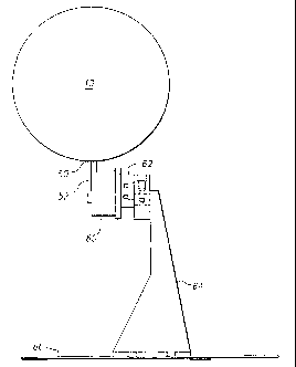
As shown in Figures 6, 7, 8a and 8b, the entire
table and probe, sensor, and holder assembly are mounted in
a vertical orientation to support stand assemblies 62, 64, one
for each end of the rotor. The stands are heavy-duty steel
"stiff-kneel" type gussets and include bracketed aluminum
plates 62. In order to support the bracketed aluminum plates
62, the mounting faces of the supporting stands 64 are milled
flat. These stands 62 are designed to be bolted down to a
floor 66. In addition, neoprene sponge gaskets (not shown)
are used between the bases of the support stands 64 and the
floor 66 in order to minimize vibration. As shown in Figures
6,7, 8a and 8b, the stands 64 are designed so that the
positioning tables 60 bolt directly to the mounting faces of
the aluminum plates 62 via through-holes. In addition, the
mounting holes are slotted to allow the table 60 to be leveled
accurately with respect to the rotor body 10.
Cables (not shown) necessary for the connection of
instrumentation (probes and tables) are connected to the
anemometer main unit and traversing control equipment (not
shown). In the preferred embodiment of the invention, the
length of cables between the anemometer main unit and the
probe 54 are limited to 20 meters in order for the electronics
to function correctly. In the preferred embodiment of the
invention, the output of the anemometer main unit is connected
to a NicoletT"" 410 signal-averaging storage oscilloscope (not
shown) by a coaxial cable . The scope accepts a continuous
analog response signal from the anemometer 50 in real-time,
and digitizes and averages the signal over a designated number
of scans, or "sweeps". The number of sweeps and time interval
between sweeps are defined by the operator. The averaged
digital signals are then stored to a floppy disk in ASCII
format via a disk drive integral to the scope.
Tests were performed to determine the optimal
position of the probe, the appropriate calibration of the
CA 02251224 1998-10-07
WO 97/38288 PCT/US96/04957
- - 10 -
probe, and the optimal number of sweeps to be averaged to
yield a high quality signal. It has been found that the
response is clearer and more consistent when the sensor is
positioned close to the rotor body (the closer the better the
response). As a consequence, in the preferred embodiment of
the invention, it is prudent to place the sensor as close to
the spinning rotor body as safety of the probe permits. In
the preferred embodiment of the invention, this distance is
approximately .100 inches (.254 cm) (from .05 inches (.13 cm)
to .15 inches (.38 cm)).
In the preferred embodiment of the invention, the
sensors are calibrated to 100 m/s and 200 m/s. During tests,
it was determined that sensors calibrated in the range of 0-50
m/s were occasionally subject to saturation. In particular,
although the average velocity of flow was within this range,
during testing it was noted that the anemometer signal
occasionally became saturated indicating that the
instantaneous velocity exceeded 50 m/s. If saturation occurs
during testing, the average values stored in the scope will
be distorted. Thus, in order to avoid saturation, the sensors
used in the preferred embodiment of the invention are
calibrated to 100 m/s and 200 m/s.
During initial testing, it was necessary to average
approximately 20 sweeps before the signal became recognizable
when the signal is sampled at 5 microsecond intervals. The
quality of the signal increased with the number of sweeps
averaged. Based on these tests, in the preferred embodiment
of the invention, 500 sweep averages are used. As a
consequence, in the preferred embodiment of the invention for
a rotor shown in Figure 1 spinning at 3600 RPM, the probe is
placed as close as possible to the rotor, the calibration is
set to 100 m/s and 200 m/s, the signal at 5 microsecond
intervals and at least 500 sweeps per average are used.
Another consideration is the orientation of the
probe to the rotation of the rotor 10, i.e., to the axis of
rotation of the rotor, and the use of shields for the probe.
At running speed (3600 RPM) , the rotor surface and, therefore,
CA 02251224 1998-10-07
WO 97/38288 PCT/CTS96/04957
- 11 -
the air adjacent to it, is travelling at a velocity of 628
ft/sec (192 m/s) . This velocity is significantly greater than
the velocity of the air exiting the circumferential vent
holes. The velocity of air exiting the circumferential vent
holes varies from about 150 ft/s to 60 ft/s (46 m/s to 18
m/s). Various shielding configurations were tested to
determine whether they blocked the shear flow component. In
addition, probe orientation was investigated to determine
whether the orientation of the probe would remove the shear
flow component.
In detail, when the probe is oriented parallel to
the rotor body, the time response of the sensor is the
greatest but the sensor is exposed to the full effects of the
shear flow. When the probe is orientated perpendicular to the
rotor body, the time response of the probe is slightly reduced
but the sensor is relatively insensitive to the shear flow
component. To determine the optimal probe configuration, the
orientation of the sensor fiber with respect to the axis of
the rotor was changed from perpendicular to parallel while the
radial distance of the sensor from rotor body was varied
between 0.11 and 0.511 inches (.28 to 1.3 cm). The optimal
configuration being when the sensor is placed 0.11 inches for
the surface of the rotor body and perpendicular to the axis
of rotation of the rotor body.
The testing also showed that the magnitude of the
signal decreases rapidly when the sensor is moved away from
the rotor body. For example, at 0.511 inches (1.3 cm) away
from the rotor body, the individual vent flows are almost
indistinguishable when the probe is in a perpendicular
orientation; however, a defined pattern still exists with the
probe in a parallel orientation. When the sensor is 0.11
inches (.28 cm) from the rotor surface and oriented parallel
to the rotor axis, the peak velocities at the vents are 120-
110 m/s and the velocities along the pole region (no vents)
are about 55 m/s. In the perpendicular orientation, the peak
velocities at the vent exits are 55-60 m/sec while the
velocities along the pole region are approximately 20 m/sec.
CA 02251224 1998-10-07
WO 97/38288 PCT/US96/04957
- - 12 -
The differences between the velocities in the vented region
are due to the absence of the shear velocity component present
when the probe is in the parallel orientation.
Nevertheless, as noted above, the measured velocity
in the pole region with the sensor perpendicular to the rotor
axis is still not zero. This is due primarily to the fact
that the hot film anemometer is insensitive to the direction
of flow. For example, when the mean velocity along the
surface is zero, there are still turbulent fluctuations which
are characterized by random positive and negative flows.
Since the anemometer measures only the magnitude of velocity
of flow and not its direction, the positive and negative flows
do not cancel and thus the sensor detects or determines the
average or RMS turbulence level on the surface of the rotor
body.
The testing also showed that velocities measured by
the sensor at the pole regions (not vents) are relatively
insensitive to the sensor's distance from the rotor body when
the sensor has an orientation perpendicular to the rotor axis .
The velocities measured by the sensor at the pole regions,
however, drops off steadily with the sensor's increased
distance from the rotor body when the sensor has an
orientation parallel to the rotor axis. This data further
indicated that the velocity measured by the sensor in the pole
region is primarily the RMS turbulence level when the sensor
has an orientation perpendicular to the rotor axis, whereas,
the velocity measured by the sensor in the pole region is the
shear velocity when the sensor has an orientation parallel to
the rotor axis.
In view of the above observations, in the preferred
embodiment of the invention, the most meaningful and accurate
signal is obtained when the sensor is approximately 0.100
inches ( . 254 cm) away from the rotor surface and the fiber of
the sensor has an orientation perpendicular to the rotor axis .
Figure 9 illustrates f low velocity measurements taken with the
sensor in this preferred position for circumferential vent
hole number 15 of the rotor 10. As shown in Figure 9, each
CA 02251224 1998-10-07
WO 97/38288 PCT/US96/04957
- - 13 -
of the 12 circumferential vent holes for a pole of the rotor
is characterized by a sharp peak followed by a much smaller
peak . The sharp peak corresponds to the f low exiting the vent
hole (15) and the small peak corresponds to the RMS
5 turbulence.
Tests of the probe with various shields were also
performed and indicated that the probe operated satisfactorily
without a shield. All of the shielding tests were performed
with the probe oriented perpendicular to the rotor axis. Due
10 to the orientation of the probe, these tests only evaluated
the effect of the shield on the base anemometer signal. The
first shield tested had a semi-circular shape which was
integral to the micarta rod probe holder. During this test,
the holder was simply slid up on the probe so that the
upstream side of the sensor was shielded. The test showed
that with the first shield in place, the baseline turbulence
along the pole region increased from 18 m/s to 23 m/s.
Overall, the effect of the first shield on the anemometer
signal was small.
A second shield was also tested. The second shield
had a U-shaped, "shoehorn" style configuration. The geometry
or shape of this shield was designed to block any axially
entrained flow in addition to the shear flow. The second
shield significantly affected the surrounding flow. In
particular, the baseline turbulence increased to about 26 m/s
and the characteristic signals from the circumferential vents
were significantly altered. The tests indicated that the
second shield was unacceptable because it greatly distorted
the flow. As a consequence, in the preferred embodiment of
the invention, the probe is not shielded.
Although the invention has been described in terms
of a preferred embodiment, the spirit and scope of the
appended claims are unlimited by any details not expressly
stated in the claims. For example, further tests may be
performed to determine whether the first shield, i.e., the
semi-circle, or other similarly configured shields, may aid
in the measurement of flow from vents in a spinning rotor.