Note: Descriptions are shown in the official language in which they were submitted.
CA 02251252 1998-10-07
WO 97/39369 _1- PCT/US97/03323
VARIABLE PITCH STRUCTURED OPTICAL FILM
Field of the Invention
The present invention relates to the field of structured optical films and
optical displays incorporating the structured optical films. More
particularly, the present
invention relates to optical films having a structured surface in which the
pitch of the
valleys and/or peaks vary.
to Back!'round of the Invention
Structured optical films are used in optical display systems and in other
applications where control over the direction of light, transmitted and/or
reflected, is
desired to increase brightness, reduce glare, etc. Structured optical films
are described
generally in U.S. Patent No. 4,906,070 (Cobb). Essentially, they comprise
films of light
15 transmissible materials in which a series of prisms are located such that
the films can be
used to redirect light through reflection and refraction. When used in an
optical display
such as that found in laptop computers, watches, etc., the structured optical
film can
increase brightness of an optical display by limiting light escaping from the
display to
within a pair of planes disposed at desired angles from a normal axis nlnning
through the
20 optical display. As a result, light that would exit the display outside of
the allowable
range is reflected back into the display where a portion of it can be
"recycled" and
returned back to the structured film at an angle that allows it to escape from
the display.
That recycling is useful because it can reduce power consumption needed to
provide a
display with a desired level of brightness.
25 An undesirable effect of using a structured optical film in an optical
display is the appearance of reflected moire caused by the interference of two
periodic
patterns. Moire effects are discussed in O. Bryngdahl, "Moire: Formation and
Interpretation," OpticaActa, Vol. 24(1), pp. 1-13 (1977). In an optical
display
incorporating a single layer of structured optical film, the periodic patterns
causing
3o moire are the pattern in the film itself and the reflected image of the
film pattern (as
reflected by other surfaces in the optical display).
Some optical displays incorporate a second structured optical film in
which the prisms are oriented at an angle with the prisms in the first optical
film. That
CA 02251252 1998-10-07
WO 97/39369 _2_ PCT/US97/03323
angle can be anywhere from greater than zero to 90 , although it is typically
about 90 .
Although using two structured optical films can increase the brightness of the
display
within a narrowed viewing range, it can increase the effects of moire by
providing a
second piano surface (on the lower structured film) that reflects more light
back through
the periodic pattern in the first, or upper, structured film.
In addition, the second structured optical film may also lead to optical
coupling that may result in uneven light transmission from the display, i.e.,
visible bright
spots, streaks, andlor lines in the display. Optical coupling is caused by
contacting, or
very nearly contacting, a piano surface with the structured surface of a
structured optical
1o film.
Summary of the Invention
The present invention includes a structured optical film with variable
pitch peaks and/or grooves to reduce the visibility of moue interference
patterns and
15 optical displays incorporating one or more layers of the film.
In one embodiment, the present invention includes a structured optical
film having a structured surface that includes a plurality of generally
parallel peaks, each
pair of adjacent peaks being separated by a valley; a first group of adjacent
peaks having
a first peak pitch; and a second group of adjacent peaks having a second peak
pitch, the
2o second group of adjacent peaks being located adjacent to the first group of
adjacent
peaks, wherein the first peak pitch is different than the second peak pitch.
The first
group preferably includes 20 or fewer adjacent peaks, more preferably 10 or
fewer and
even more preferably 3 or fewer peaks. Alternatively, the first group can be
defined in
terms of width, with one preferred width being about 0.5 millimeters or less,
more
25 preferably about 200 micrometers or less. It is also preferable that the
valley pitch
within the first group varies over any three adjacent valleys.
In another embodiment, the present invention includes a structured
optical film having a structured surface that includes a plurality of
generally parallel
valleys, each pair of adjacent valleys being separated by a peak; a first
group of adjacent
3o valleys having a first valley pitch; and a second group of adjacent valleys
having a
second valley pitch, the second group of adjacent valleys being located
adjacent to the
first group of adjacent valleys, wherein the first valley pitch is different
than the second
CA 02251252 1998-10-07
WO 97/39369 _3- PCT/US97/03323
valley pitch. The first group preferably includes 20 or fewer adjacent
valleys, more
preferably 10 or fewer, and even more preferably 3 or fewer valleys.
Alternatively, the
first group can be defined in terms of width, with one preferred width being
about 0.5
millimeters or less, more preferably about 200 micrometers or less. It is also
preferable
that the peak pitch within the first group varies over any three adjacent
peaks.
In yet another embodiment, the present invention includes a structured
optical film having a structured surface, wherein the structured surface
comprises a
plurality of generally parallel valleys, each pair of adjacent valleys being
separated by a
peak, wherein the peak pitch is substantially constant, and further wherein
the valley
to pitch varies within a group of three or more successive adjacent valleys.
In still another embodiment, the present invention includes a structured
optical film having a structured surface, wherein the structured surface
comprises a
plurality of generally parallel peaks, each pair of adjacent peaks being
separated by a
valley, wherein the valley pitch is substantially constant, and further
wherein the peak
is pitch varies within a group of three or more successive adjacent peaks.
The above and other features of the inven'on are more fully shown and
described in the drawings and detailed description of this invention, where
like reference
numerals are used to represent similar parts. It is to be understood, however,
that the
description and drawings (which are not to scale) are for the purposes of
illustration
20 only and should not be rea~ in a manner that would unduly limit the scope
of this
rnventron.
Brief Descriation of the Drawings
FIGURE 1 is a perspective view of a prior art structured optical film.
2s FIGURE 2 is a perspective view is an exploded perspective view of a
pair of structured films according to Fig. 1 in which the prisms are crossed
at an angle of
about 90 .
FIGURE 3A is a schematic diagram of one section of a structured film
according to the present invention with a constant peak pitch and a varying
valley pitch.
3o FIGURE 3B is a schematic diagram of one section of a structured film
according to the present invention with a constant valley pitch and a varying
peak pitch.
CA 02251252 1998-10-07
WO 97/39369 ~ PCT/US97/03323
FIGURE 4A is a schematic diagram of one section of an alternative
structured film according to the present invention with a varying peak pitch.
FIGURE 4B is a schematic diagram of one section of an alternative
structured film according to the present invention with a varying valley
pitch.
FIGURE SA is a schematic diagram of one section of an alternative
structured film according to the present invention with a varying peak pitch
and a
varying valley pitch.
FIGURE SB is a schematic diagram of one section of an alternative
structured film according to the present invention with a varying peak pitch
and a
to varying valley pitch.
FIGURE 6 is a schematic diagram of an optical display assembly
incorporating at least one layer of structured optical film according to the
present
invention.
Detailed Description of the Invention
The present invention, described in connection with the illustrative
embodiments depicted in Figure 3A and the following figures, provides a
structured
optical film in which the peak pitch and/or valley pitch vary to reduce the
visibility of the
moire interference patterns when using one or more layers of the structured
films in, for
2o example, an optical display.
Figures 1 and 2 generally illustrate the concept of structured optical
films. Figure 1 depicts a section of a regular, periodic structured optical
film 10
including a structured surface 12 and a piano surface 14. The structured
surface
includes a series of regularly spaced valleys 16 and peaks 18 that define
prisms 20. The
prisms 20 are defined by facets formed between the valleys 16 and peaks 18.
The
geometry of the structured surface 12 and the material used to manufacture the
film 10
foster total internal reflection and refraction of light entering the piano
side 14 of film I O
to minimize the escape of light through the structured surface outside of the
desired
range of angles.
3o Figure 2 illustrates a pair of structured optical films 22 and 24 in which
the prisms 26 and 28, respectively, are oriented at approximately 90 angle
with respect
CA 02251252 1998-10-07
WO 97/39369 -5- PCT/US97/03323
to each other. In use, it is preferred that the structured surface 28 be in
contact with, or
nearly in contact with, the piano surface 27 of the upper film 22.
Although the prisms/facets generally depicted in connection with the
present invention are shown as having a dihedral angle of about 90 between
generally
planar facets, it will be understood that the present invention includes
structured optical
films having prisms/facets formed in any optically useful shape, including
lenticular
arrays, prisms with rounded peaks and/or valleys, curved facets, etc. In other
words,
the present invention is useful with any structured optical film displaying a
periodic
pattern that could result in visible moire interference patterns in the
absence of variations
1o in pitch as described herein. Furthermore, although the embodiments
discussed below
include a piano surface, it will be understood that the opposing surface of
the structured
optical films manufactured according to the present invention, i.e., the
surface opposite
the structured surface, could be substantially planar or it could be provided
with a
structure, texture, as a smooth surface, or with any other finish as desired.
15 It should also be understood that the embodiments depicted in Figures
3A and following are generally planar cross-sections of structured optical
films
constructed according to the present invention taken generally perpendicular
to the
length of the grooves/valleys. Given the variable nature of the optical films
according to
the present invention (to reduce the visibility of moire interference
patterns), it will be
2o understood that the cross-sections of a given film may or may not remain
constant along
the length of the grooves/valleys. This may be particularly true in the
structured optical
films manufactured according to the present invention using tooling
constructed by
thread cutting a cylindrical roll.
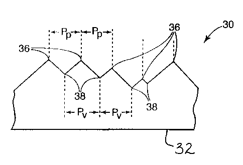
Figure 3A schematically depicts a cross-section, normal to the piano
25 surface 32, of one structured optical film 30 according to the present
invention. The film
30 includes a set of prisms defined by peaks 36 and valleys 38. The peaks 36
and valleys
38 defining the prisms are preferably substantially parallel to each other
although slight
variations would be acceptable. The spacing between adjacent peaks 36, i.e.,
the peak
pitch, of the optical film 30 is substantially constant. The spacing between
adjacent
30 valleys 3 8, however, varies over any group of three successive valleys 3
8. That spacing
between valleys 38 can also be referred to as valley pitch, Pv. By varying the
valley
CA 02251252 1998-10-07
WO 97/39369 _6_ PCT/US97/03323
pitch, the visibility of moire interference patterns can be reduced when using
film 30 in
an optical display.
The peak pitch in a film 30 manufactured according to the present
invention will preferably be about I millimeter or less, more preferably the
peak pitch
will be about 100 micrometers or less when the structured filin 30 is used in
optical
displays incorporating liquid crystal display panels and similar devices. More
preferably,
the peak pitch for those applications will lie within about 20 to about 60
micrometers.
An optical film 30 can be produced using a tool manufactured by any
known method. If the tool used to produce the film 30 is a roll, it can be
manufactured
to by thread cutting at a constant thread pitch, plunge cutting using a
constant spacing
between grooves, or any other useful method. It is preferred to form each
groove in the
tool to a constant, but differing, depth when forming the tool used to
manufacture the
film 30.
If the tool used to form the film 30 is a cylindrical roll formed using
15 thread cutting, it is preferred to constantly vary the depth of the groove
formed in the
roll by a cutting tool. That variation could include varying the depth of the
groove at a
constant or changing rate between a minimum and maximum, although it may also
be
helpful to have interim targeted depths between the minimum and maximums that
are
interspersed about the circumference of the roil to avoid adding periodicity
into the
2o grooves and, thus, the film.
When thread cutting, it may also be desirable to vary the number of
revolutions, or "wraps," over which the cutting tool is moved between
different targeted
groove depths and, also, to use a number of roll revolutions between targeted
depths
that is not an integer. Even more preferably, it is desirable to use a number
of
25 revolutions including a fractional portion that is not easily multiplied to
equal an integer.
Examples of useful numbers of revolutions over which groove depth would be
varied
include, for example, 0.85, 1.15, I.3, or 2.15. The targeted depth of the
groove would
then vary between the starting and ending point of each desired number of
revolutions of
the roll.
3o After the tool is manufactured, the film 30 can be manufactured using the
tool according to any suitable method. Examples of methods and materials for
forming
structured optical films are discussed in U.S. Patent Nos. 5,175,030 (Lu et
al.) and
CA 02251252 2001-04-11
WO 97/39369 _7_ PCT/US97/03323
5,183,597 (Lu). It will be understood that the chosen manufacturing process is
at least
somewhat dependent on the material used for the films.
In the film 30 depicted in Figure 3A ~ peak pitch is held constant while the
valley pitch varies. The tooling used to manufacture the film 30 can, however,
be
replicated by electroforming or other suitable processes, thus forming a
"negative" of
the pattern formed on the master tool. When that replicated tool is then used
to form a
film, the result, depicted in Figure 3B, is a film 130 that is a "negative" of
the film 30
depicted in Figure 3A. As a result, film 130 has a constant valley pitch, Pv,
between
valleys 136 while the peak pitch, Pp, between peaks 138 vanes across the film
130.
to That is exactly the opposite of the pitch characteristics of the film 30.
Like film 30, the
film 130 in Figure 3B is also useful for reducing the visibility of moire
interference
patterns when used in an optical display.
The valley pitch in a film 130 manufactured according to the present
invention will preferably be about 1 millimeter or less, more preferably the
valley pitch
will be about 100 micrometers or less when the structured film 30 is used in
optical
displays incorporating liquid crystal display panels and similar devices. More
preferably,
the valley pitch for those applications will lie within about 20 to about 60
micrometers.
Figure 4A is a schematic diagram of an alternative structured optical film
40 that includes a piano surface 42 and structured surface 44. Structured
surface 44
2o includes a plurality of generally parallel prisms defined by peaks 46 and
valleys 48. The
peaks 46 are all preferably formed with substantially the same height, Hp,
above the
piano side 42 of the film.
In the film 40, the peak pitch, Ppl, remains constant over a first group 50
of peaks 4G. A second group 52 of peaks 46 is located immediately adjacent to
the first
group 50. The second group 52 of peaks 46 has a constant peak pitch, Ppl, that
is
different from the peak pitch of the ftrst group 50. It is the variation in
peak pitch that
contributes to reducing the visibility of moire interference,pattetns when
using film 40.
The peak pitch in a film 40 manufactured according to the present
invention will preferably be about 1 nullimeter or less, more preferably the
peak pitch
3o will be about 100 micrometers or less when the structured film 140 is used
in optical
displays incorporating liquid crystal display panels and sinular devices. More
preferably,
the peak pitch for those applications will lie within about 20 to about 60
micrometers.
CA 02251252 1998-10-07
WO 97/39369 PCT/US97/03323
_g_
Typical peak pitches used in connection with the present invention include
groups of
peaks spaced at 50, 40, 30 and 20 micrometers. It may be helpful to provide
maximum
peak pitch to minimum peak pitch ratios of about 1.25 or greater, more
preferably about
1.5 or greater and even more preferably about 2.0 or greater to reduce the
visibility of
moire interference patterns.
The number of peaks 46 in each of the groups can be varied to improve
moire interference reduction. The film 40 includes groups 50 and 52 in which
groups of
three adjacent peaks 46 have a constant peak pitch. In some structured films
according
to the present invention, it may be helpful where at least one of the groups
has about 20
to or fewer peaks; preferably about 10 or fewer; more preferably about 5 or
fewer; and
even more preferably about 3 or fewer peaks. In some structured films, it may
also be
helpful to include only two adjacent peaks 46 in a group, i.e., provide a
pattern in which
the peak pitch vanes between successive pairs of peaks.
Although the film 40 includes only two groups 50 and 52, it will be
15 understood that the present invention includes films having at least two or
more groups
of peaks, i.e., the film 40 could include any number of groups, not just two
groups.
Also, although the film 40 is shown as having two groups with equal numbers of
peaks
46, it will be understood that each group may include the same or different
number of
peaks 46.
2o An alternative measure of the group size can be based on the width of the
groups as measured generally perpendicular to the peaks and valleys.
Preferably, the
width of each group is about 1 millimeter or less, more preferably about 0.5
millimeters
or less, more preferably about 200 micrometers, more preferably about 100
micrometers
or less, and even more preferably about 50 micrometers or less. It will be
understood
25 that, in part, the desired group widths are based on the pitch of the peaks
and valleys in
the film 40.
An optical film 40 can be produced using a tool manufactured by any
suitable method. It will be understood that the height of the peaks, Hp, in
the finished
film 40 is a function of the depth of the grooves cut into the tool. If the
tool used to
3o produce the film 40 is a cylindrical roll, it can be manufactured by thread
cutting the roll
to a constant depth at a constant thread pitch over the grooves used to form
each group
of peaks having a constant peak pitch. If thread cutting is used to form a
roll, it is
CA 02251252 1998-10-07
WO 97/39369 -9_ PCT/C1S97/03323
desirable to hold the thread pitch constant for a number of roll revolutions
that is not an
integer. Even more preferably, it is desirable to hold the thread pitch
constant for a
fractional number that is not easily multiplied to equal an integer. Examples
of useful
numbers of revolutions over which thread pitch could be held constant include,
for
example, 0.85, 1.15, 1.3, or 2.15. It will be understood that the integer
portion of the
number of revolutions over which thread pitch is held constant determines the
number of
peaks in each of the groups.
After the tool is manufactured, the film 40 can be manufactured using the
tool according to any suitable method. Examples of methods and materials for
forming
to structured optical films are discussed in U.S. Patent Nos. 5,175,030 (Lu et
al.) and
5,183,597 (Lu). It will be understood that the chosen manufacturing process is
at least
somewhat dependent on the material used for the films.
The tooling used to manufacture the film 40 can be replicated by
electroforming or other suitable processes, thus forming a "negative" of the
pattern
is formed on the master tool. When that replicated tool is then used to form a
film, the
result, depicted in Figure 4B, is a film I40 that is a "negative" of the film
40 depicted in
Figure 4A. As a result, the valley pitch, Pv, in film 140 remains constant
over a first
group 150 of valleys 146. A second group 152 of valleys 146 is located
immediately
adjacent to the first group 150. The second group 152 of valleys 146 has a
constant
2o valley pitch, Pvl, that is different from the valley pitch of
the first group 150. It is the variation in valley pitch that contributes to
reducing the
visibility of moire interference patterns when using film 140.
The valley pitch in a film 140 manufactured according to the present
invention will preferably be about 1 millimeter or less, more preferably the
valley pitch
25 will be about 100 micrometers or less when the structured film 140 is used
in optical
displays incorporating liquid crystal display panels and similar devices. More
preferably,
the valley pitch for those applications will lie within about 20 to about 60
micrometers.
Typical valley pitches used in connection with the present invention include
groc~ps of
peaks spaced at 50, 40, 30 and 20 micrometers. It may be helpful to provide
maximum
3o valley pitch to minimum valley pitch ratios of about 1.25 or greater, more
preferably
about 1.5 or greater and even more preferably about 2.0 or greater to reduce
xhe
visibility of moire interference patterns.
CA 02251252 1998-10-07
WO 97/39369 -lo- PCT/LTS97/03323
The number of valleys 146 in each of the groups can be varied to reduce
the visibility of moire interference patterns. The film 140 includes groups
I50 and 152
in which groups of three adjacent valleys 146 have a constant valley pitch. In
some
structured films according to the present invention, it may be helpful where
at least one
of the groups has about 20 or fewer valleys; preferably about 10 or fewer;
more
preferably about 5 or fewer; and even more preferably about 3 or fewer
valleys. In some
structured films, it may also be helpful to include only two adjacent valleys
146 in a
group, i.e., provide a pattern in which the valley pitch varies between
successive pairs of
valleys.
to Although the film 140 includes only two groups 150 and 152, it will be
understood that the present invention includes films having at least two or
more groups
of evenly-spaced valleys, i.e., the film 140 could include any number of
groups, not just
two groups. Also, although the film 140 is shown as having two groups with
equal
numbers of evenly-spaced'valleys 146, it will be understood that each group
may include
the same or different number of valleys 146.
An alternative measure of the group size can be based on the width of the
groups as measured generally perpendicular to the peaks and valleys.
Preferably, the
width of each group is about 1 millimeter or less, more preferably about 0.5
millimeters
or less, more preferably about 200 micrometers, more preferably about 100
micrometers
or less, and even more preferably about 50 micrometers or less. It will be
understood
that, in part, the desired group widths are based on the pitch of the peaks
and valleys in
the film 140.
After the replicated tool is manufactured, the film 140 can be
manufactured according to any suitable method. Examples of methods and
materials for
forming structured optical films are discussed in U.S. Patent Nos. 5,175,030
(Lu et al.)
and 5,183,597 (Lu). It will be understood that the chosen manufacturing
process is at
least somewhat dependent on the material used for the films.
Turning now to Figure SA, a cross-section of another alternative
structured optical film 60 according to the present invention is shown in a
schematic
3o diagram as including a piano surface 62 and a structured surface 64.
Structured surface
64 includes a plurality of generally parallel prisms defined by peaks 66 and
valleys 68.
CA 02251252 1998-10-07
WO 97/39369 PCT/US97/03323
-I1-
Structured film 60 includes goups of peaks 66 with constant peak pitch.
The peak pitch, Ppl, remains constant over a first goup 70 of peaks 66. A
second
goup 72 of peaks 66 is located immediately adjacent to the first goup 70. The
second
goup 72 of peaks 66 has a constant peak pitch, Ppl, that is di$'erent from the
peak
pitch of the first goup 70.
The number of peaks 66 in each of the groups can be varied to reduce the
visibility of moire interference patterns caused by the film 60. The film 60
includes
goups 70 and 72 in which groups of three adjacent peaks 66 have a constant
peak pitch.
In some structured filins according to the present invention, it may be
helpful where at
least one of the goups has about 20 or fewer peaks; preferably about 10 or
fewer; more
preferably about 5 or fewer; and even more preferably about 3 or fewer peaks.
In some
structured films, it may also be helpful to include only two adjacent peaks 66
in a goup,
i.e., provide a pattern in which the peak pitch varies between successive
pairs of peaks.
An alternative measure of the group size in film 60 can be based on the
width of the groups as measured generally perpendicular to the peaks and
valleys.
Preferably, the width of each group for many applications is about 1
millimeter or less,
more preferably about 0.5 millimeters or less, more preferably about 200
micrometers,
more preferably about 100 micrometers or less, and even more preferably about
SO
micrometers or less. It will be understood that, in part, the desired goup
widths are
2o based on the pitch of the peaks and valleys in the structured film 60.
Although the film 60 is depicted with only two groups 70 and ?2, it will
be understood that the present invention includes films having at least two or
more
goups of peaks, i.e., the film could include any number of goups, not just two
goups.
Also, although the film 70 is shown as having two groups with equal numbers of
peaks
66, it will be understood that each goup may include the same or different
number of
peaks 66.
An optical film 60 can be produced using a tool manufactured by any
known method. It will be understood that the height of the peaks in the
finished film is a
function of the depth of the gooves cut into the tool. If the tool used to
produce the
3o film 60 is a cylindrical roll, it can be manufactured by thread cutting the
roll at a constant
thread pitch over the gooves used to form each group of peaks having a
constant peak
pitch, i.e., the number of revolutions at any given thread pitch will define
the number of
CA 02251252 1998-10-07
WO 97/39369 -12_ PCT/CTS97/03323
grooves foamed at that thread pitch (which also corresponds to the number of
peaks
with the given peak pitch).
If thread cutting is used to form a roll, it is desirable to hold the thread
pitch constant for a number of roll revolutions that is not an integer. Even
more
preferably, it is desirable to hold the thread pitch constant for a fractional
number that is
not easily multiplied to equal an integer. Examples of useful numbers of
revolutions
over which thread pitch could be held constant include, for example, 0.85,
1.15, 1.3, or
2.15. It will be understood that the integer portion of the number of
revolutions over
which thread pitch is held constant detenmines the number of peaks in each of
the
1o groups.
While thread pitch (and, therefore, peak pitch) are varied as discussed
above, the depth of the grooves on the tool used to manufacture the film 60
can also be
varied to change the valley pitch as well. If the tool is formed by thread
cutting, it is
preferred to constantly vary the depth of the groove formed in the cylindrical
roll. That
variation could include varying the depth at a constant or changing rate
between a
minimum and maacimum, although it may also be helpful to have interim targeted
depths
between the minimum and maximums that are interspersed about the circumference
of
the roll to avoid adding periodicity to the grooves and, thus, the film 60
formed using
the tool.
2o It may also be desirable to vary the number of revolutions it takes to
move between different targeted groove depths and, also, to use a number of
roll
revolutions between targeted depths that is not an integer. Even more
preferably, it is
desirable to use a number of revolutions including a fractional portion that
is not easily
multiplied to equal an integer. Examples of useful numbers of revolutions over
which
groove depth would be varied include, for example, 0.85, 1.15, 1.3, or 2.15.
The
targeted depth of the groove would then vary between the starting and ending
point of
each desired number of revolutions of the roll.
The changes between targeted cutting tool depths, i.e., groove depths,
may correspond to the changes in thread pitch about the roll, or
alternatively, the
3o changes in targeted tool depths may be independent of the changes in thread
pitch. In
other words, the number of revolutions over which groove depth changes can be
the
CA 02251252 2001-04-11
WO 97/39369 -13_ PCT/US97/03323
same as or different than the number of revolutions aver which the thread
pitch remains
constant within a group.
After the tool is manufactured, the film 60 can be manufactured using the
tool according to any suitable method. Examples of methods and materials for
forming
structured optical films are discussed in U.S. Patent Nos. 5,175,030 (Lu et
al.) and
5,183,597 (Lu). It will be understood that the chosen manufacturing process is
at least
somewhat dependent on the material used for the films.
The peak pitch in a film 60 manufactured according to the present
invention will preferably be about 1 millimeter or less, more preferably the
peak pitch
to will be about 100 micrometers or less when the structured film 60 is used
in optical
displays incorporating liquid crystal display panels and similar devices. More
preferably,
the peak pitch for those applications will lie within about 20 to about 60
micrometers.
Typical peak pitches used in connection with the present invention include
groups of
i
peaks spaced at 50, 40, 30 and 20 micrometers. It may be helpful to provide
maximum
15 peak pitch to minirrrum peak pitch ratias of about 1.25 or greater, more
preferably about
1.5 or greater and even more preferably about 2.U or greater to reduce the
visibility of
moire interference patterns.
In addition to varying pitch (peak and valley) any of the structured
optical films manufactured according to the present invention may also include
2o structures in the film 60 that prevent or reduce optical coupling. The film
60 is depicted
as including taller peaks 66' at each end of the depicted array that can
provide the
desired spacing between film 6U and a smooth or piano surface (not shown)
above the
film 60 to prevent, or at least reduce, optical coupling. One preferred
spacing, or pitch,
between_the peaks 66' is about 709 micrometers, although any desired spacing
could be
2s provided.
The tooling used to manufacture the film 60 can be replicated by
electroforming or other suitable processes, thus forming x"negative" ofthe
pattern
formed on the master tool. When that replicated tool is then used to form a
film, the
result, depicted in figure ST3, its a Glm 160 that is a "negative" of the film
60 depicted in
CA 02251252 1998-10-07
WO 97/39369 -14- PCT/US97103323
Figure SA. As a result, structured film 160 includes goups of valleys 166 with
constant
valley pitch. The valley pitch, Pvl, remains constant over a first goup 170 of
valleys
166. A second goup 172 of valleys 166 is located immediately adjacent to the
first
goup 170. The second group 172 of valleys 166 has a constant valley pitch,
Pvz, that
is different from the valley pitch of the first goup 170.
The number of valleys 166 in each of the goups can be varied to reduce
the visibility of moue interference patterns caused by the film 160. The film
160
includes goups 170 and 172 in which goups of three adjacent valleys 166 have a
constant valley pitch. In some structured films according to the present
invention, it
1o may be helpful where at least one of the goups has about 20 or fewer
valleys; preferably
about 10 or fewer; more preferably about 5 or fewer; and even more preferably
about 3
or fewer valleys. In some structured films, it may also be helpful to include
only two
adjacent valleys 166 in a goup, i.e., provide a pattern in which the valley
pitch varies
between successive pairs of valleys.
Although the film 160 is depicted with only two goups 170 and 172, it
will be understood that the present invention includes films having at least
two or more
groups of evenly-spaced valleys, i.e., the film could include any number of
groups, not
just two goups. Also, although the film 170 is shown as having two goups with
equal
numbers of evenly-spaced valleys 166, it will be understood that each goup may
include
2o the same or different number of valleys 166.
An alternative measure of the group size in film 160 can be based on the
width of the goups as measured generally perpendicular to the peaks and
valleys
Preferably, the width of each goup is about 1 millimeter or less, more
preferably about
0.5 millimeters or less, more preferably about 200 micrometers, more
preferably about
100 micrometers or less, and even more preferably about 50 micrometers or
less. It will
be understood that, in part, the desired goup widths are based on the pitch of
the peaks
and valleys in the structured film 160.
The valley pitch used in a film 160 manufactured according to the present
invention will preferably be about 1 millimeter or less, more preferably the
valley pitch
3o will be about 100 micrometers or less when the structured film 160 is used
in optical
displays incorporating liquid crystal display panels and similar devices. More
preferably,
the valley pitch for those applications will lie within about 20 to about 60
micrometers.
CA 02251252 1998-10-07
WO 97/39369 PCT/US97/03323
-1 S-
The film 160 can be manufactured from a replicated tool according to
any suitable method. Examples of methods and materials for forming structured
optical
films are discussed in U.S. Patent Nos. 5,175,030 (Lu et al.) and 5,183,597
(Lu). It will
be understood that the chosen manufacturing process is at least somewhat
dependent on
the material used for the films.
As discussed with respect to Figure 2, two structured optical films with
varying pitch manufactured according to the present invention can be combined
in a
crossed relationship to reduce the visibility of moire interference patterns.
As an
alternative, it may be helpful to use the structured films according to the
present
1o invention for the upper layer of such a paired construction, because it is
the upper layer
that is the most significant contributor to the visibility of moire
interference patterns.
Where films according to the present invention are used for the upper film,
the lower
film could be any other suitable structured optical film usefi,~l for
enhancing brightness of
optical displays. Examples of suitable films for pairing with the structured
optical film
manufactured according to the present invention are available from Miruiesota
M'lning
and Manufacturing Company, St. Paul, Minnesota (marketed under the tradename
Brightness Enhancement Film).
Figure 6 illustrates one application in which one or more layers of
structured optical film manufactured according to the present invention can be
2o advantageously used. The application is a backlit optical display assembly
80. The
assembly 80 includes a display panel 82 and two crossed layers of structured
optical
films 84 and 86 manufactured according to the present invention. The optical
display
assembly 80 includes a backlight assembly 88 for use in those situations in
which
ambient light is insuiBcient to view the display panel 84. Although two
structured
optical films are depicted in Figure 6, it will be understood that an optical
display could
include only a single structured optical film manufactured according to the
present
invention.
Although the particular material used to manufacture structured optical
films according to the present invention may vary, it is important that the
material be
3o substantially transparent to ensure high optical transmission. Useful
polymeric materials
for this purpose are commercially available such as, for example, acrylics,
and
polycarbonates having nominal indices of refraction of about 1.493 and 1.586,
CA 02251252 1998-10-07
WO 97/39369 PCT/US97103323
-16-
respectively. Other useful polymers include acrylate, polyester,
polypropylene,
polyurethane, polystyrene, polyvinyl chloride, and the like. While the
particular material
is not critical, materials having higher indices of refraction will generally
be preferred.
Usefi~l materials for forming structured optical films are discussed in U.S.
Patent Nos.
5,175,030 (Lu et al.) and 5,183,597 (Lu).
Also, although methods of producing tooling useful for manufacturing
structured optical films according to the present invention are described
above, it will be
understood that any method of producing tooling and/or manufacturing a
structured
optical film with varying peak and/or valley pitch could be substituted. In
addition,
to although the focus of the above discussion has been on the use of
cylindrical tools for
manufacturing structured optical films according to the present invention, it
should be
understood that planar tooling could also be used to manufacture the films.
Furthermore, although thread cutting of cylindrical rolls will not produce a
film having
exactly parallel prisms, the prisms will be generally parallel for the
purposes of the
15 present invention.
The following non-limiting examples illustrate the manufacture and
features of two structured optical films according to the principles of the
present
invention.
20 Ezam~le 1
A structured optical film according to the present invention was
produced using a tool manufactured according to the following method. A
cylindrical
roll having a smooth surface was cut using a 90 cutting tool. The cutting tool
was
advanced along the axis of the roll at a constant rate of 32 micrometers for
each full
25 revolution. As the roll was rotated during cutting, the depth of the
cutting tool was
changed 16 micrometers over 0.85 revolutions to define a particular "cut" as
defined
herein. As a result, if the tool ended at a depth of 16 micrometers at the end
of a cut, it
was then moved out to depth of 0 micrometers at the end of the succeeding cut.
The film produced using the roll cut as discussed above exhibited a
3o constant peak pitch and varying valley pitch as described with respect to
Figure 3 above.
When two layers of the film so produced were crossed 90 , a moire
interference pattern was visible, but at a reduced level as compared to two
crossed
CA 02251252 1998-10-07
WO 97/39369 _17_ PCT/LTS97/03323
structured optical films with a constant peak/valley pitch. The crossed layers
exhibited a
drop in gain of about 8.6% as compared to two crossed layers of Brightness
Enhancement Film (BEF I - 90 prisms with a 50 micrometers pitch) sold by
M~lnnesota
Ivfining and Manufacturing Company, St. Paul, l~nnesota. Gain was measured
using a
backlight from Sharp Microelectronics Technology, Inc. (Camas, Washington),
Model
C12P, and a luminance meter from Photo Research (California), Model PR650
SpectraColorimeter. The measurements were taken at a distance of about'406 mm
(16
inches) above the films and centered over the films which were about I52 mm x
203 mm
(6 inches x 8 inches).
to
Eza-
A structured optical film according to the present invention was
produced using a tool manufactured according to the following method. A
cylindrical
roll having a smooth surface was cut using a 90 cutting tool. The cutting tool
was
advanced along the axis of the roll at a constant rate over 2.15 revolutions.
The rate of
advancement of the cutting tool was changed for each group of 2.15
revolutions. As the
roll was rotated during cutting, the depth of the cutting tool was also
changed from a
starting depth to an ending depth for each 2.15 revolutions. To prevent
discontinuities
in the cutting depth, the ending depth of the tool after one group of 2.15
revolutions was
2o the starting depth for the next group of 2.15 revolutions.
Gras Grotr~ 5pacit~~5txrtm~ pth Ending i3epth
~ De
::::. ..1..
_ .~.Q'~:m~Iers 1~ .. meters: ::.meteis
:, '~ ~~ v
.
1. 50 28 18
2 30 18 23
3 0 23 13
20 13 18
30 18 23
6 40 23 13
'1 20 13 18
8 30 18 23
23 18
10 30 18 28
The above array of groups was repeated until a sufficiently wide roll was
patterned to form a film. Desirably, the array included two tall peaks spaced
at either
CA 02251252 2001-04-11
WO 97/39369 1'( "1'/11597/03323
_1$_
end about 700 micrometers apart. These taller peaks provided the structure to
reduce
or prevent optical coupling.
When two layers of the film so produced were crossed, almost no moire
interference pattern was visible. The crossed layers exhibited a drop in gain
of 6% as
s compared to two crossed layers of Brightness Enhancement Film (HrF I with 90
prisms
spaced at 50 micrometers) sold by Minnesota Mining and Manufacturing Company,
St.
Paul, Minnesota. Gain was measured as described in connection with Example 1.
When a single; layer of this film was crossed with a bottom layer of
Brightness Enhancement Film II (90 prisms at a SO micrometer pitctr)
(available from
1o Minnesota IVhtning and Manufacturing Company, St Paul, Minnesota), an
increased
amount of moire interference; was observed as compared to two films
manufactured
according to the present invention. The brightness of that combination was
improved,
however, exhibiting a loss in gain of 4.2%.
15 Various modifications and alterations of this invention will become
apparent
to those skilled in the art without departing from the scope of thus
invention, and it
should be understood that trris invention is not to be unduly IimitFd to the
illustrative
embodiments set forth herein.