Note: Descriptions are shown in the official language in which they were submitted.
CA 02251594 1998-10-14
WO 97/38777 PCTIUS97/06228
APPARATUS FOR THE LARGE SCALE GROWTH AND PACKAGING OF CELL
SUSPENSIONS AND THREE-DIMENSIONAL TISSUE CULTURES
BACKGROUND OF THE INVENTION
Technical Field
The present invention relates to an apparatus for the
growth and packaging of cell suspensions and three-
dimensional tissue cultures. Specifically, the present
invention relates to a system for the large-scale culturing
and packaging of cell suspensions for cell-based and gene-
based therapies, as well as for the culturing and packaging
of human-engineered tissue constructs for a variety of
transplant applications.
Discussion of the Related Art
The seeding and culturing of tissue for use in
replacement therapy is known in the art. For example, U.S.
Patent No. 5,266,480 to Naughton et al. discloses the
establishment of a three dimensional matrix, seeding of the
matrix with desired cells, and maintenance of the culture to
provide a variety of three-dimensional tissues suitable for
use in different applications. Three-dimensional tissue has
a number of uses, including use of the tissue for treatment
of burn victims and for treatment of skin ulcers often
associated with diabetes.
Culturing of human or animal cell suspensions for cell-
based and gene-based therapies is also known in the art. For
example, in an article entitled "Effect of Autolymphocyte
Therapy on Survival and Quality of Life in Patients With
Metastatic Renal-Cell Carcinoma," The Lancet, Vol. 335, No.
8696, pp. 994-98 (April 28, 1990}, a method is disclosed in
which suspended lymphocytes are cultured in medium containing
supernatant from a culture of mononuclear cells treated with
mitogenic agents, grown for several days, and gamma-
CA 02251594 2004-11-05
irradiated immediately prior to infusion in patients. Cell-based
and gene-based therapies have a number of uses, including use of
the cells for treatment of metastatic kidney cancer and for
treatment of renal cell cancer.
Conventional means of tissue and cell culture have been
limited by the need for human supervision and control of the media
which feeds nutrients to the tissue and cells over the time needed
for the growth of the same, which limits the amount of cells and
tissue that can be cultured at a single time. For example, in an
article entitled "The In Vitro Growth of a Three-Dimensional Human
Dermal Replacement Using a Single-Pass Perfusion System" 43
Biotechnology and Bioengineering 740-746 (April 1994), a closed,
single pass perfusion system is disclosed in which growth medium
is passed through a parallel configuration of Teflon' bag
bioreactors. Each bag bioreactor contains a biodegradable mesh on
a TeflonTM frame, onto which tissue is grown. The related art
system described provides for 16 bag bioreactors, which must be
carefully handled to avoid damaging the tissue as it grows.
SOMMARY OF THE INVENTION
The present invention aims to provide a system which allows
for the large-scale culturing and packaging of cell suspensions
and three-dimensional tissue in a convenient form which enables
aseptic large-scale culturing, individual packaging, freezing,
storing, shipping, and use.
The invention further aims to provide a closed aseptic
environment from culture initiation to end use.
The invention also aims to provide a consistent culturing
environment for the uniform culture of both cell suspensions and
tissue.
In accordance with the present invention, there is provided
an apparatus for the large scale culturing and packaging of cell
suspensions and three-dimensional tissues. The apparatus
according to the invention includes a plurality of flexible
treatment chambers, a plurality of rigid spacers, an inlet fluid
manifold, an outlet fluid manifold, a fluid reservoir, and a means
for transporting fluid from the reservoir to the treatment
2
CA 02251594 2004-11-05
chambers. During treatment, liquid,media is transported from the
fluid reservoir to the inlet manifold, which will in turn evenly
distribute the media to each of the connected treatment chambers.
An outlet fluid manifold is also provided to ensure that each
treatment chamber is evenly filled and to ensure that any air
bubbles formed during media transport are removed from the
treatment chambers.
The treatment chambers are advantageously flexible so as to
provide for gas permeability, and thus, large scale culturing
through the use of minimal mechanical components. Treatment
chamber flexibility is additionally advantageous in that it allows
for easy end-user handling during rinsing and application of the
cultured transplants. Due to the flexibility of the treatment
chambers, rigid spacers are also provided which ensure even fluid
distribution within the chambers during treatment.
The invention provides an apparatus, comprising: a plurality
of treatment chambers each treatment chamber comprising flexible
front and back sheets bonded together along predetermined
boundaries to delimit a first port for the inflow of fluid into
each said treatment chamber, a second port for the outflow of
fluid from each said treatment chamber, and at least one
compartment for growth of cells or tissue; at least one substrate
disposed within each said treatment chambers designed to
facilitate three-dimensional cell or tissue growth on said
substrate; a plurality of spacer members adapted to contact each
said treatment chamber in a manner which maintains even fluid
distribution within each said treatment chamber, thereby promoting
even growth of cells or tissue; an apparatus inlet manifold with
an inlet port and a plurality of outlet ports for uniformly
providing fluid to each said treatment chamber, each said outlet
port adapted to mate with the first port of each said treatment
chamber; an apparatus outlet manifold with a plurality of inlet
ports, each inlet port adapted to mate with the second port of
each said treatment chamber; and a support member for
3
CA 02251594 2004-11-05
connecting said plurality of spacer members to said apparatus
inlet and apparatus outlet manifolds.
The invention also provides an apparatus for promoting the
growth of cells or tissue, comprising: a plurality of treatment
chambers defined by flexible front and back walls, each said
treatment chamber having a first port and a second port for flow
of fluid therethrough; at least one substrate disposed within each
of said plurality of treatment chambers designed to facilitate
three-dimensional cell or tissue growth on said substrate; an
apparatus inlet manifold with an inlet port and a plurality of
outlet ports, each of said outlet ports in fluid communication
with each said first port of each said treatment chamber; a supply
of fluid in fluid communication with the inlet port of said
apparatus inlet manifold; fluid transportation means for supplying
fluid to the inlet port of said apparatus inlet manifold; an
apparatus outlet manifold with a plurality of inlet ports, each of
said inlet ports in fluid communication with each said second port
of each said treatment chamber.
In this manner, the invention advantageously utilizes a
compact and mechanically non-complex apparatus to maintain an
aseptic and uniform environment for the large-scale culturing and
individual packaging of cell suspensions, three-dimensional
tissues, and other biological systems.
BRIEF DESCRIPTION OF THE DRAWINGS
These and other features, aspects, and advantages of the
present invention will become more readily apparent from the
following detailed description, which should be read in
conjunction with the accompanying drawings in which:
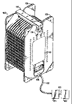
FIGS. 1A - 1D illustrate a first exemplary embodiment of a
system for the large scale culturing and packaging of cell
suspensions and three-dimensional tissues, wherein FIGS. lA and 1B
are perspective views of the system, FIG. 1C is a perspective view
of the system with one end plate removed,
3a
CA 02251594 1998-10-14
WO 97/38777 PCT/US97/06228
and FIG. 1D is an alternative embodiment of a single rigid
spacer; _
FIGS. 2A - 2B illustrate a first embodiment of a
treatment chamber, wherein FIG. 2A is a top plan view of the
treatment chamber, and FIG. 2B is a perspective view of the
components of the treatment chamber prior to manufacture of
the chamber;
FIGS. 3A - 3D illustrate an alternative exemplary
embodiment of a system for the large scale culturing and
packaging of cell suspensions and three dimensional tissues,
wherein FIG. 3A is perspective view of the system including
rigid spacers, FIG. 3B is a perspective view of the system
without rigid spacers, FIG. 3C is a perspective view of an
inlet fluid manifold, and FIG. 3D is a perspective view of a
fluid inlet piece of the inlet fluid manifold;
FIGS. 4A - 4D illustrate a rigid spacer for use in a
culturing system, wherein FIG. 4A is a perspective view of
the rigid spacer, FIG. 4B is a top plan view of the rigid
spacer, FIG. 4C is a side view of the rigid spacer, and FIG.
4D is an end view of the rigid spacer;
FIGS. 5A - 5J illustrate yet another alternative
embodiment of a system for the large scale culturing and
packaging of cell suspensions and three dimensional tissues,
wherein FIG. 5A is perspective view of the system, FIG. 5B is
a perspective view of the system with the outlet manifold
removed, FIG. 5C is a perspective view of a bottom portion of
an inlet fluid manifold, FIG. 5D is a top plan view of a
center portion of an inlet fluid manifold, FIG. 5E is top
plan view of a lock plate for a manifold, FIG. 5F is a
perspective view of a rigid spacer, FIG. 5G is a perspective
view of support structure for a plurality of rigid spacers,
FIG. 5H is a top view of a central portion of an outlet fluid
manifold, FIG. 51 is a top view of an upper portion of an
outlet fluid manifold, and 5J is a perspective view of a
system support rod;
FIG. 6 is a top plan view of an alternative exemplary
embodiment of a treatment chamber; and
- 4 -
CA 02251594 1998-10-14
WO 97/38777 PCT/US97/06228
FIGS. 7A - 7B illustrate yet another alternative
exemplary embodiment of a treatment chamber, wherein FIG. 7A
is a top plan view of the treatment chamber, and FIG. 7B is a
perspective view of the components of the treatment chamber
prior to manufacture of the chamber.
DETAILED DESCRIPTION OF THE INVENTION
The following embodiments of the present invention will
be described in the context of an apparatus for the large
scale growth and packaging of cell suspensions and three-
dimensional tissues, although those skilled in the art will
recognize that the disclosed methods and structures are
readily adaptable for broader application. Note that
whenever the same reference numeral is repeated with respect
to different figures, it refers to the corresponding
structure in each such figure.
In accordance with the present invention, multiple
treatment chambers are manifolded together during growth and
culturing of transplants. These treatment chambers are
advantageously flexible so as to provide for gas permeability
and easy end-user handling during rinsing and application of
the cultured transplants. However, flexible treatment
chambers are not ideal for maintaining a constant culturing
environment within the chambers during treatment. For
example, if a vertical chamber orientation is utilized during
treatment so as to facilitate the removal of potentially
disruptive air bubbles away from the enclosed transplants,
the flexible chambers will tend to bulge at the bottom. This
distortion of the chambers during treatment creates an
irregular and uneven culturing environment for the
transplants. In addition, the distortion of the chamber can
alter the surface area for oxygen transfer of the expansive,
gas-permeable chambers, further compromising uniform
production of cells and tissue for a given volume of media.
Accordingly, rigid spacers are provided which may be
adapted to ensure even fluid distribution within the chambers
during treatment. More particularly, proper fluid
- 5 -
CA 02251594 1998-10-14
WO 97/38777 PCT/US97/06228
distribution is maintained by positioning each treatment
chamber within the system between the rigid spacers in a
configuration that ensures that fluid within each chamber is
evenly distributed in much the same manner as would occur
with the use of properly formed and defined rigid chambers.
In accordance with the foregoing, FIGS. 1A - 1D disclose
a system 100 for the large scale culturing and packaging of
biological systems such as cell suspensions and three
dimensional tissues. According to a first embodiment of the
invention, this system primarily comprises a plurality of
treatment chambers 106, a plurality of rigid spacers 107, an
inlet fluid manifold 108, and an outlet fluid manifold 110
connected to both an overflow bag 112 and a vent filter 114,
a fluid reservoir 102, and a means for transporting fluid
from the fluid reservoir to the treatment chambers such as
pump 104.
Fluid reservoir 102 is used to store fluid for the
system. An illustrative suitable reservoir is any flexible
1L media bag, although one skilled in the art will understand
that any fluid container capable of sterilization may be
utilized. Examples of fluid which may be used in the system
include, but are not limited to, fluid containing cells,
fluid containing a culture medium, and fluids comprising
various freezing solutions. It is to be understood that
during culturing, the fluid may be advantageously kept at
human body temperature.
The fluid contained in reservoir 102 is retrieved
through fluid line 103 by a fluid delivery method such as
pump 104. Although pump 104 is used herein in describing the
structure and function of the invention, it is to be
understood that other suitable means for transporting fluid
would also fall within the scope of the invention. For
example, fluid may be forced out of reservoir 102 and into
fluid line 103 through the use of a common source of
compressed gas, such as a house supply of clean, compressed
nitrogen. Alternatively, fluid may be transported by gravity
- 6 -
CA 02251594 1998-10-14
WO 97/38777 PCTIUS97/06228
feed from a fluid reservoir placed at a higher elevation than
the treatment chambers and manifolds themselves.
Fluid line 103, as well as all other fluid lines in
the system, may be made of any type of sterilizable, durable
tubing suitable for transporting the fluid in use. Pump 104
may be preferably any fluid pump which can achieve variable
and bi-directional flow rates. One such pump is the
Masterflex L/S Digital Drive peristaltic pump manufactured by
Cole-Palmer, although one skilled in the art could select
from a variety of commercially available pumps. Pump 104
propels the fluid from reservoir 102 to inlet fluid manifold
108 through fluid line 105.
As shown in FIGS. 1A - 1C, multiple treatment chambers
106 may be manifolded together utilizing inlet fluid manifold
108. The internal surfaces of inlet fluid manifold 108 can
be advantageously angled and configured so as to ensure that
any air bubbles entering the manifold are not trapped within
the manifold itself. In order to ensure proper distribution
of fluids into the multiple treatment chambers 106 when
filling the same, system 100 should be oriented vertically
such that the inlet manifold 108 is directly below treatment
chambers 106 and outlet manifold 110. When system 100 is
oriented in this manner, gravity will ensure that the fluid
within the system equilibrates among the multiple
iriterconnected treatment chambers.
As shown in FIG. 2A, a small length of narrow diameter
tubing 202 at the inlet of treatment chambers 106 may be used
within the system. If the system is to be operated in a
continuous fluid circulation mode by connecting the outlet
manifold 110 back to fluid reservoir 102, this narrow tubing
202 is advantageous as it will create a pressure drop between
each treatment chamber and the inlet manifold 108. The
pressure drop will further ensure proper fluid distribution
within chambers 106 during treatment. In this continuous
fluid circulation mode, the optimum diameter and tolerances
for tubing 202 will depend at least in part upon the actual
- 7 -
CA 02251594 1998-10-14
WO 97/38777 PCT/US97/06228
fluid flow rate used during treatment and upon the dimensions
of inlet manifold 108.
FIGS. 2A - 2B illustrate a first embodiment of a
treatment chamber 106 which may be manifolded together in
system 100. As shown in FIGS. 2A - 2B, treatment chambers
106 include both an inlet port 202 and an outlet port 204.
Treatment chambers 106 may also be configured and
dimensioned to house multiple tissue scaffolds 206. Tissue
scaffolds 206 are preferably comprised of any biocompatible
mesh material. Suitable materials include VicrylTM, which is
produced by Ethicon, Inc., Somerville, New Jersey, and
polyglycolic acid (PGA) mesh, which is produced by Albany
International, Mansfield, Massachusetts and Davis & Geck,
Danbury, Connecticut. Scaffolds 206 may be spot welded or
bar welded within treatment chamber 106 at their corners
(points A in FIG. 2A) so as to ensure the mesh will be held
in place during treatment. Alternatively, scaffolds 206 may
be sandwiched between welds during production of the
treatment chamber itself, or welded or stitched to a rigid or
semi-rigid frame, which could then be welded to the treatment
chamber or simply confined within the treatment chamber by
the outer weld demarcating each individual culture pocket.
Especially for thinner tissue scaffolds, anchorage of the
scaffold to the chamber is important during treatment to
resist contractile forces which could cause the tissue to
bunch or curl upon itself.
In addition to the bioabsorbable VicrylTM and PGA meshes,
scaffolds 206 may also be comprised of a nylon and silicone
rubber combination such as BiobraneTM, which is produced by
Dow-Hickam. These silicone rubber membranes may serve as an
artificial epidermis in use, and only require a growth system
in which media contacts one side of the membrane. Therefore,
when using BiobraneTM material in treatment chamber 106, spot
welding need not be performed as the Biobrane' material can
be placed directly on the inside surface chamber and will
maintain proper positioning due to electrostatic and
hydrophobic forces.
- 8 -
CA 02251594 1998-10-14
WO 97/38777 PCT/US97/06228
Although only PGA mesh, Vicryl"" mesh, and BiobraneTM have
been disclosed, one skilled in the art will understand that
other mesh types and support structures are possible within
the scope of this invention. In addition, although FIGS. 2A
and 2B illustrate chamber 106 housing only six scaffolds 206,
one skilled in the art will understand that any number of
scaffolds 206 may be housed in treatment chamber 106. It is
to be additionally understood that for certain cell-based
therapies, no scaffolding may be required.
As illustrated in FIG. 2B, treatment chamber 106 may be
manufactured by welding two pieces of film 210 together in a
predetermined pattern. Film 210 must be biocompatible and
must be able to maintain structural and compositional
integrity under the sterilization/cultivation and freeze/thaw
cycles which will be described in more detail below. In
short, film 210 must be able to withstand irradiation,
chemical, or thermal treatments to sterilize the treatment
chambers 106 prior to culturing. In addition, the film 210
should preferably withstand freezing and storage at
temperatures under -70 C, which is required to preserve the
cultured cells or tissue, as well as subsequent thawing to
room or body temperature once the cells or tissue are
required for use. As a stagnant fluid system can be employed
during culturing, film 210 should also be gas permeable so as
to support tissue growth. In addition, film 210 must be
amenable to reliable and readily available sealing and
welding methods, which include heat, RF, and ultrasonic
welding.
Any flexible materials which meet the above-specified
requirements may preferably be considered for construction of
treatment chambers 106. As mentioned previously, the
plurality of treatment chambers may be advantageously
flexible so as to provide for easy end-user handling during
rinsing and application of the cultured transplants.
Examples of acceptable flexible materials include
polyolefins, polyolefin co-polymers, EVA and EVA copolymer
blends, Exact , PVC, PTFE, FEP, high density polyolefins, and
- 9 -
CA 02251594 1998-10-14
WO 97/38777 PCT/US97/06228
thermoformed plastics, with EVA and EVA copolymer blends
being most preferable due to the low cost, ease of
fabrication, and optical clarity.
To ensure proper growth and culturing of the tissue,
treatment chambers 106 should be formed in such a manner that
ensures air bubbles do not lodge near scaffolds 206. A
preferred pattern, shown in FIGS. 2A and 2B, containing
angled sides (preferably >= 5 degrees) along culture pockets
210, along with a vertical orientation during culturing (a
horizontal orientation may also be used, and would also fall
within the scope of the invention, but is not the preferred
means of treatment), will ensure that any potentially
disruptive air bubbles contained in the culturing fluid will
be guided toward channel 212 and outlet port 204, and thus
away from culture pockets 210 and tissue scaffolds 206.
Treatment chambers 106 may additionally include welded
islands 214 in flow channel 212. These islands 214 are
advantageous as they reduce the amount of welding which must
be performed to separate the culture pockets 210 into
individual storage chambers after treatment. Islands 214 are
also advantageous as they provide an opening for support rods
ill (as depicted in FIG. 1C) and prevent fluid from simply
channeling up the center of the treatment chamber (i.e.,
fluid is directed into the side culture pockets). Point B in
FIG. 2A indicates where the post-treatment welding preferably
occurs, and thus indicates the savings in post-treatment
welding provided by islands 214.
As mentioned, vertical orientation during treatment will
assist in moving potentially disruptive air bubbles away from
scaffolds 206. However, vertical orientation also forces
fluid to accumulate near the bottom of the flexible,
expansive chambers 106. Proper fluid volume and distribution
is therefore advantageously maintained by positioning each
treatment chamber 106 between rigid spacers 107. Rigid
spacers 107 may be corrugated as shown in FIGS. 1A - 1C, or
may contain perforations, as shown in FIG. 1D, so that
adequate gas and heat transfer may occur while still
- 10 -
CA 02251594 1998-10-14
WO 97/38777 PCT/US97/06228
maintaining even fluid distribution within the treatment
chambers.
The positioning of chambers 106 between spacers 107 is
additionally advantageous in that it will minimize contact
between the chambers themselves, and between the chambers and
personnel overseeing the cell or tissue treatment.
Minimization of contact is preferable as such contact can
result in damage to the treatment chambers and/or expose
personnel to the potentially harmful contents of the
treatment chambers.
As shown in FIGS. 1A - 1C, a number of treatment
chambers 106 and spacers 107 may be supported by end plates
109 and rods 111 which provide the structural stability and
rigidity required for the precise application of force
required to achieve a predetermined fluid distribution and
volume in each treatment chamber. The combination of end
plates, rods, and spacers is additionally beneficial as it
provides a rigid structure which protects the flexible
treatment chambers from accidental rupture during processing,
thus promoting aseptic and safe culture of the cells or
tissue. End plates 109, like spacers 107, may be perforated
or corrugated to ensure adequate gas and heat transfer in the
treatment chambers positioned directly against the end plates
during use. Spacers 107, end plates 109, and rods 111 may be
comprised of any rigid, durable material such as styrene,
aluminum, magnesium, polycarbonate, Teflon, PVC, high density
polyolefins, or stainless steel.
In an alternative embodiment, end plates 109 and rods
ill are not utilized as the means for ensuring structural
integrity. In this alternative embodiment, spacers 107 need
simply be attached to inlet manifold 108 and outlet manifold
110 in any manner known in the mechanical arts which would
ensure structural integrity similar to that seen with the use
of the combination of rods and end plates.
Once all treatment chambers 106 have been filled with
fluid from reservoir 102 during use, fluid will exit chambers
106 through outlet ports 204 into outlet fluid manifold 110.
- 11 -
CA 02251594 2004-11-05
Outlet fluid manifold 110 may be connected to an overflow bag 112
and/or an air filter 114 so as to provide for the removal of
excess air and fluid from the system. Like fluid reservoir 102,
overflow bag 112 may illustratively comprise a flexible plastic 1L
media bag, although one skilled in the art will understand that
any container capable of sterilization may be utilized.
Alternatively, and as previously mentioned, system 100 may
include only one fluid reservoir which functions as both the
reservoir from which fluid may be retrieved as well as the
reservoir to which fluid may be dispensed. In this configuration,
once the fluid media is ready to be removed from the system, fluid
may be dispensed to the fluid reservoir simply by reversing pump
direction, or alternatively, utilizing gravity to drain the fluid
from the system. This single-reservoir configuration
advantageously provides a closed, aseptic, and compact culturing
environment. Outlet manifold 110 may also be connected to air
filter 114 which facilitates the removal of unwanted air bubbles
from the system during treatment and which facilitates the even
and rapid filling of the treatment chambers 106.
Seeding and culturing of cell suspensions and three-
dimensional tissue in treatment chambers 106 is generally
accomplished by known techniques, with the added benefits and
advantages gained from the novel large scale culturing systems
disclosed herein. Examples of suitable seeding and culturing
methods for the growth of three-dimensional cell cultures are
disclosed in U.S. Patent No. 5,266,480. The techniques described
in U.S. Patent No. 5,266,480 for establishing a three-dimensional
matrix, inoculating the matrix with the desired cells, and
maintaining the culture may also be readily adapted by a person of
ordinary skill in the art for use with the present invention.
Known techniques for the culturing of cell suspensions for cell-
based or gene-based therapies may also be readily adapted for use
with the present invention.
12
CA 02251594 1998-10-14
WO 97/38777 PCTIUS97/06228
Once all treatment chambers have been filled with the
appropriate seeding and culturing medium in accordance with
the structure described herein, and in accordance with known
seeding and culturing techniques, tubing connecting upper
manifold 110 to overflow bag 112, the overflow bag 112 to the
vent filter 114, and tubing 105 connecting inlet manifold 108
and pump 104 may be clamped shut.
Once this tubing is clamped shut, system 100 may be
rotated about one of its axes so as to maintain the
suspension of cells during the culture of cell suspensions,
and so as to ensure uniform seeding of tissue scaffolds
during the culture of the same. In the case of tissue
culture, once the tissue scaffolds have been uniformly
seeded, the system can, but need not be rotated for the
remainder of the culturing process.
During the seeding and culturing of cells and tissue,
system 100 may be advantageously placed in a controlled
environment enclosure, in which environmental parameters such
as temperature, as well as oxygen and carbon dioxide
concentrations, may be controlled as necessary to achieve
desired growth conditions.
Once the tissue scaffolds have reached the desired level
of cell density, the culture medium may be pumped out of the
system and replaced with a freezing solution so as to
facilitate cryopreservation of the tissue. When the
treatment chambers have been filled with the freezing
solution, the inlet ports 202 and outlet ports 204 of the
treatment chambers may then be sealed so as to create a
sealed chamber which may then be removed from system 100.
In the case of cell suspension cultures which do not
require scaffolding, treatment chambers 106 containing the
cell suspensions may not require the introduction of a
freezing solution and may be simply sealed shut.
Once sealed treatment chambers 106 have been removed
from system 100, individual culture pockets 210 may then be
sealed and separated as explained above. These individual
pockets can be sealed through any of the established welding
- 13 -
CA 02251594 1998-10-14
WO 97/38777 PCTIUS97/06228
methods mentioned above, and separated through the use of a
known die-cutting operation or through the use of tear seals.
The individual pockets may then be frozen using conventional
freezing methods, or, alternatively, the entire multiple-
piece chamber may be frozen as one unit, depending upon the
clinical application. In this manner, sealed treatment
chambers 106 may be used to culture, store, and ship cells,
tissue cultures, and other biological systems.
FIGS. 3A - 3D disclose an alternative exemplary
embodiment of a system for the large scale culturing and
packaging of cell suspensions and three dimensional tissue.
Alternative embodiment 300 primarily comprises a fluid
reservoir 102, a pump 104, a plurality of treatment chambers
106, a plurality of spacers 306, an inlet fluid manifold 312,
an outlet fluid manifold 314, an overflow bag (which may be
embedded in end plate 310), and a vent filter 315.
Fluid reservoir 102 and pump 104 function in the same
manner as those described in conjunction with FIGS. 1A - 1D
above. In particular, reservoir 102 is used to store fluid
for the system, while pump 104 is used to provide fluid to
and retrieve fluid from the system. As mentioned, although
pump 104 is used herein in describing the structure and
function of present invention, it is to be understood that
other suitable means for transporting fluid would also fall
within the scope of the present invention.
As shown in FIG. 3A, inlet fluid manifold 312 may be
used to manifold together multiple treatment chambers 106
(not shown in FIG. 3A), which are described in conjunction
with FIGS. 2A - 2B above. Inlet fluid manifold 312 is
illustrated more particularly in FIGS. 3C and 3D. As shown
in FIGS. 3C and 3D, inlet fluid manifold may be comprised of
a lock plate 324, a connector plate 322, and a fluid inlet
piece 320. Lock plate 324 may be used to secure tubing 202
of the growth chambers to the fluid manifold. Specifically,
tubing 202 may fit securely within one of the plurality of
openings 330 in connector plate 322. Connector plate 322
functions to secure the fluid manifold 312 to end plate 309
- 14 -
CA 02251594 1998-10-14
WO 97/38777 PCT/US97/06228
as shown in FIGS. 3A and 3B. Fluid inlet piece 320 includes
a longitudinally extending fluid channel_321 and fluid inputs
323 so as to facilitate the flow of fluid from the fluid
reservoir to each opening 330 and thus each treatment chamber
106 in the system. Fluid channel 321 is preferably
configured so as to ensure that no air bubbles become trapped
in the manifold itself.
As shown in FIGS. 3A - 3B, treatment chambers 106 and
rigid spacers 306 may be supported by rods 308 in conjunction
with end plates 309 and 310. This combination of end plates
and rods provides the structural stability and rigidity
required for the precise application of force to treatment
chambers 106 to achieve a predetermined fluid distribution in
each chamber during treatment. More particularly, the
vertical orientation of chambers 106 during treatment
gravitationally forces fluid within the flexible chamber to
accumulate near the bottom of such chambers. Accordingly,
proper fluid distribution of fluid is advantageously
maintained by positioning each treatment chamber 106 between
rigid spacers 306 which are in turn stabilized by the
combination of end plates 309 and 310 along with rods 308.
FIGS. 4A - 4D disclose an exemplary embodiment of rigid
spacers 306. As shown in FIGS. 4A - 4D, spacers 306 include
sections 402 for slidably mating with slots 316 of end plates
309 and 310. Sections 402 preferably include a smooth outer
surface so as to facilitate this mating. Spacers 306 also
include a central area comprised of two flat surfaces 404
attached by edge pieces 405. Edge pieces 405 rigidly support
a predetermined width between surfaces 404. Surfaces 404 may
also include semi-circular sections 410 which allow for easy
access to chamber tubing 202 and 204 during use. This ease
of access is advantageous for visual observation of fluid
distribution and for welding of tubing 202 and 204 after
treatment, but prior to disengagement from the system. In
addition, surfaces 404 may also include open areas 412 which
allow for various end user features on the treatment chambers
such as side ports (shown in FIG. 2A).
- 15 -
CA 02251594 1998-10-14
WO 97/38777 PCT/US97/06228
Surfaces 404 may also include perforated areas 406
which, along with the spacing between surfaces 404, allow for
adequate gas and heat transfer from chambers 106 during
treatment, but do not compromise the maintenance of even
fluid distribution within the chambers themselves. One
example of a suitable perforation pattern is a 60 pattern
with 500 open air and with holes less than 0.5 inches in
diameter. However, one skilled in the art will understand
that other perforation patterns are equally suitable and
equally acceptable. These perforated areas 406 may be
advantageously positioned in areas which will contact those
regions of chambers 106 which are occupied by scaffolds 206
or cell suspensions. Spacers 306 may preferably be comprised
of any rigid material such as stainless steel, Teflon , or
polycarbonate.
Once all treatment chambers 106 have been filled with
fluid, fluid will exit chambers 106 through outlet port 204
into outlet fluid manifold 314. Outlet fluid manifold 314
may be connected, like outlet manifold 110 described in
conjunction with FIGS. 1A - 1D above, to an overflow bag
(which may be embedded in end plate 310) and an air vent
filter 315. Alternatively, system 300 may include only one
fluid reservoir which functions as both the reservoir from
which fluid may be retrieved as well as the reservoir to
which fluid may be dispensed.
The seeding, culturing, freezing, and storage of cells
or tissue scaffolds 206 in treatment chambers 106 is
generally accomplished by the techniques described above in
conjunction with system 100. In addition, during culture of
cells or tissue, system 300, like system 100, may be
advantageously placed in a controlled environment enclosure,
in which environmental parameters such as temperature, as
well as oxygen and carbon dioxide concentrations, may be
controlled as necessary to achieve desired growth conditions.
FIGS. 5A - 5J disclose yet another alternative exemplary
embodiment of a system for the large scale culturing and
packaging of cell suspensions and three dimensional tissue.
- 16 -
CA 02251594 1998-10-14
WO 97/38777 PCTIUS97/06228
According to this alternative embodiment 500 of the
invention, the system primarily comprises a fluid reservoir
102, a pump 104, a plurality of treatment chambers 600, a
plurality of spacers 512, an inlet fluid manifold 514, and an
outlet fluid manifold 502 connected to a hydrophobic air
filter 522. Fluid reservoir 102 and pump 104 function in the
same manner as those described in conjunction with FIGS. 1A -
1D above.
As shown in FIGS. 5A - 5J, inlet fluid manifold 514 may
be used to manifold together multiple treatment chambers 600,
one exemplary embodiment of which is described in conjunction
with FIG. 6 below. Inlet manifold 514 is comprised of a lock
plate 508, a center portion 518, and a bottom portion 520.
Center portion 518 and bottom portion 520 form the manifold
fluid channels, while lock plate 508 may be configured and
adapted to secure the treatment chamber inlet ports to the
manifold itself. In addition, an o-ring may be placed in
groove 535 (shown in FIG. 5C) so as to create a sealed
manifold chamber.
Fluid from pump 104 and fluid line 105 may enter inlet
manifold 514 through inlets 533. Alternatively one inlet may
be used as an inlet, while the other may be used as an outlet
so as to drain fluid from the system. From inlet 533, fluid
may pass to multiple apertures 530 and 532 (shown in FIGS. SD
and 5E) through channels 534 (shown in FIG. 5C). In this
fashion, fluid may be evenly distributed from the fluid
reservoir 102 to each of the attached treatment chambers 600.
As previously discussed, the vertical orientation of the
treatment chambers during treatment gravitationally forces
fluid within the flexible chamber to accumulate near the
bottom of such chambers. Accordingly, proper even
distribution of fluid is advantageously maintained by
positioning each treatment chamber between rigid spacers 512
which are in turn stabilized by spacer supports 510.
FIGS. 5F and 5G, respectively, disclose preferred
embodiments of rigid spacers 512 and spacer supports 510. As
shown in FIG. 5F, spacers 512 form a gap 513 of a
- 17 -
CA 02251594 1998-10-14
WO 97/38777 PCT/US97/06228
predetermined width between two flat surfaces. It is within
this formed gap 513 where treatment chambers 600 may be
positioned so as to ensure proper fluid distribution during
treatment. These spacer surfaces may also be corrugated or
may include perforations which, along with the spacing
between spacers 512, allow for adequate gas and heat transfer
from treatment chambers 600 during treatment, but do not
compromise the maintenance of even fluid distribution within
the chambers. As mentioned, one example of a suitable
perforation pattern is a 60 pattern with 500 open air and
with holes less than 0.5 inches in diameter. However, one
skilled in the art will understand that other perforation
patterns are equally suitable and equally acceptable. These
perforated areas may be advantageously positioned in regions
of the spacers which will contact those areas of the chambers
occupied by the tissue scaffolding or the cell suspensions.
Spacers 512, along with the other components of system 500,
may preferably be comprised of any rigid material such as
stainless steel, Teflon , or polycarbonate.
Once all treatment chambers 600 have been filled with
fluid during treatment, fluid will exit the chambers through
their outlet ports into outlet fluid manifold 502. Outlet
fluid manifold 502 may be connected, like outlet manifold 110
described in conjunction with FIGS. 1A - 1D above, to an
overflow bag and an air vent filter. Alternatively, and as
shown in FIG. 5A, system 500 may include only an air
filter 522, which may be secured within outlet manifold 504.
In yet another alternative embodiment, system 500 may include
only one fluid reservoir which functions as both the
reservoir from which fluid may be retrieved as well as the
reservoir to which fluid may be dispensed.
Outlet manifold 502 may be comprised of a lock plate
508, a central portion 506, and an upper portion 504. Lock
plate 508 allows for the firm attachment of the outlets of
treatment chambers 600 to the outlet manifold, while central
portion 506 and upper portion 504 form the fluid channels of
manifold. In addition, an o-ring may be placed in grooves
- 18 -
CA 02251594 1998-10-14
WO 97/38777 PCT/US97/06228
538 so as to create a sealed outlet manifold chamber, which
as mentioned above, may be used to house-an air filter 522.
As also shown in FIGS. 5B and 5J, treatment chambers 600
and rigid spacers 512, along with the inlet and outlet
manifolds, may be supported by a support rod 523. The
combination of manifolds 502 and 514, along with rod 523,
provides the structural stability and rigidity required for
the precise application of force required to achieve a
predetermined volume and distribution of fluid in each
treatment chamber during treatment.
The seeding, culturing, freezing, and storage of the
tissue scaffolds 206 in treatment chambers 600 within system
500 is generally accomplished by the techniques described
above in conjunction with system 100. In addition, during
culture of cells or tissue, system 500, like systems 100 and
300, may be advantageously placed in a controlled environment
enclosure, in which environmental parameters such as
temperature, as well as oxygen and carbon dioxide
concentrations, may be controlled as necessary to achieve
desired growth conditions.
FIG. 6 illustrates yet another embodiment of a treatment
chamber which may be utilized individually or may be
manifolded together in systems such as systems 100, 300, and
500. As shown in FIG. 6, treatment chamber 600 may include
both an inlet port 602 and an outlet port 604. Treatment
chamber 600 may also be configured and dimensioned to house a
tissue scaffold 206 such as described in conjunction with
FIGS. 2A and 2B above. As also described above, scaffold 206
may, if necessary, be spot welded within the chamber 600 at
its corners to ensure that the scaffolding remains in place
during treatment. Alternatively, scaffold 206 may be
sandwiched between welds during production of the treatment
chamber itself, or welded or stitched to a rigid or semi-
rigid frame, which could then be welded to the treatment
chamber or simply confined within the treatment chamber by
the outer weld demarcating each individual culture pocket.
- 19 -
CA 02251594 1998-10-14
WO 97/38777 PCT/US97/06228
Like treatment chamber 106, treatment chamber 600 may be
manufactured by welding two pieces of flexible film together
in a predetermined configuration. The film must be
biocompatible and must be able to maintain structural and
compositional integrity under the sterilization/cultivation
and freeze/thaw cycles which were previously described in
detail. Because a stagnant fluid system can be employed
during culturing, film 210 should also be gas permeable to
support tissue growth. In addition, film 210 must be
amenable to reliable and readily available sealing and
welding methods, which include heat, RF, and ultrasonic
welding.
Any flexible materials which meet the above-specified
requirements may preferably be considered for construction of
chamber 600. As mentioned previously, the plurality of
treatment chambers may be advantageously flexible so as to
provide for easy end-user handling during rinsing and
application of the cultured transplants. Examples of
acceptable flexible materials include polyolefins, polyolefin
co-polymers, EVA and EVA copolymer blends, Exact(~), PVC, PTFE,
FEP, high density polyolefins, and thermoformed plastics,
with EVA and EVA copolymer blends being most preferable due
to the low cost, ease of fabrication and optical clarity.
To ensure proper growth and culturing of the tissue,
chamber 600 should be configured and dimensioned in such a
manner that ensures air bubbles do not lodge near scaffolds
206 during treatment. The preferred pattern shown in FIG. 6
containing an angled top and bottom (preferably >= 5
degrees), along with a vertical orientation during culturing,
will ensure that any potentially harmful air bubbles
contained in the culturing fluid will be guided toward outlet
port 604, and thus away from tissue scaffolds 206.
FIGS. 7A and 7B illustrate a third embodiment of a
treatment chamber which may be utilized individually or may
be manifolded together in systems such as systems 100, 300,
and 500. As shown in FIGS. 7A and 7B, treatment chamber 700
may include both an inlet port 701 and an outlet port 703.
- 20 -
CA 02251594 1998-10-14
WO 97/38777 PCT/US97/06228
However, if treatment chamber 700 is not to be used in a
manifolded configuration such as systems,100 and 300,
treatment chamber 700 need not include both inlet and outlet
ports. Treatment chamber 700 may also be configured and
dimensioned to house a tissue scaffold 706.
Tissue scaffold 706, like scaffold 206, is preferably
comprised of any biocompatible mesh material. Suitable mesh
materials include VicrylTM mesh and polyglactin or PGA mesh.
Especially for thinner tissue scaffolds, anchorage of the
scaffold to the chamber is important during treatment to
resist contractile forces which could cause the tissue to
bunch or curl upon itself. Accordingly, scaffold 706 may be
attached on either side to frames 704. Frames 704 may be
configured in a grid pattern, as shown in FIGS. 7A and 7B,
although one skilled in the art will understand that other
patterns may be appropriate in various clinical situations.
Scaffold 706 may be attached to frames 704 in any manner
although established welding methods such as RF, ultrasonic,
or heat welding are preferred.
In addition to the bioabsorbable VicrylTM and PGA meshes,
scaffold 706 may also be comprised of a nylon and silicone
rubber combinations such as BiobraneTm. Because BiobraneTM
only requires a growth system in which media contacts one
side of the membrane, and because it will maintain proper
positioning due to electrostatic and hydrophobic forces,
BiobraneTM material can be placed directly on the surface of
frames 704. As mentioned previously, although only Biobrane,
PGA mesh, and Vicryl'm mesh have been disclosed, one skilled
in the art will understand that other tissue types and
support structures are possible within the scope of this
invention.
As shown in FIG. 7B, treatment chamber 700 may be
manufactured by welding the framed scaffold 706 in between
two pieces of film 702. Film 702 and frame 704 must be
biocompatible and must be able to maintain structural and
compositional integrity under the sterilization/cultivation
and freeze/thaw cycles which were described in detail above.
- 21 -
CA 02251594 1998-10-14
WO 97/38777 PCTIUS97/06228
Because a stagnant fluid system can be employed during
culturing, film 702 should also be gas permeable to support
growth for the tissue. Finally, film 702 should be amenable
to reliable and readily available sealing and welding
methods.
Any materials which meet the above-specified
requirements may preferably be considered for construction of
chamber 700. Examples of acceptable materials include
polyolefins, polyolefin co-polymers, EVA and EVA copolymer
blends, Exact , PVC, PTFE, FEP, high density polyolefins, and
thermoformed plastics, with EVA and EVA copolymer blends
being most preferable due to its low cost, ease of
fabrication and optical clarity.
Various embodiments of the invention have been described
herein. The descriptions are intended to be illustrative,
not limitative. Thus, it will be apparent to those skilled
in the art that modifications may be made to the invention as
described without departing from the scope of the claims set
out below.
25
35
- 22 -