Language selection

Search

Patent 2251735 Summary

Third-party information liability

Some of the information on this Web page has been provided by external sources. The Government of Canada is not responsible for the accuracy, reliability or currency of the information supplied by external sources. Users wishing to rely upon this information should consult directly with the source of the information. Content provided by external sources is not subject to official languages, privacy and accessibility requirements.

Claims and Abstract availability

Any discrepancies in the text and image of the Claims and Abstract are due to differing posting times. Text of the Claims and Abstract are posted:

  • At the time the application is open to public inspection;
  • At the time of issue of the patent (grant).
(12) Patent: (11) CA 2251735
(54) English Title: SYSTEM AND METHOD FOR DETERMINING STRAIN
(54) French Title: SYSTEME ET METHODE DE MESURE DES DEFORMATIONS
Status: Term Expired - Post Grant Beyond Limit
Bibliographic Data
(51) International Patent Classification (IPC):
  • G01B 11/16 (2006.01)
  • G01L 01/24 (2006.01)
  • G01L 11/02 (2006.01)
(72) Inventors :
  • SCHANZE, KIRK (United States of America)
  • MORRIS, MARTIN (United States of America)
(73) Owners :
  • UNIVERSITY OF FLORIDA
  • MCDONNELL DOUGLAS CORPORATION
(71) Applicants :
  • UNIVERSITY OF FLORIDA (United States of America)
  • MCDONNELL DOUGLAS CORPORATION (United States of America)
(74) Agent: MARKS & CLERK
(74) Associate agent:
(45) Issued: 2003-11-18
(86) PCT Filing Date: 1997-03-13
(87) Open to Public Inspection: 1997-10-23
Examination requested: 1998-10-14
Availability of licence: N/A
Dedicated to the Public: N/A
(25) Language of filing: English

Patent Cooperation Treaty (PCT): Yes
(86) PCT Filing Number: PCT/US1997/003852
(87) International Publication Number: US1997003852
(85) National Entry: 1998-10-14

(30) Application Priority Data:
Application No. Country/Territory Date
08/631,955 (United States of America) 1996-04-15

Abstracts

English Abstract


A system (50) for determining strain includes: a stimulating light source (54,
56); a device (64) for placing stress on an object (58); a number of local
strain gauges (66) attached to the object (58); and an image capturing device
(62, 64). A controller (52) is coupled to the stimulating light source (54,
56) and has a signal that turns on the stimulating light source (54, 56). The
controller (52) receives a strain signal from each of the local strain gauges
(66) located on the object (58). The controller (66) has an image signal that
determines when the image capturing device (62, 64) captures an image.


French Abstract

Système (50) permettant de déterminer les contraintes, constitué: d'une source de lumière de stimulation (54, 56); d'un dispositif (64) permettant d'exercer une contrainte sur un objet (58); de plusieurs jauges de contraintes locales (66) fixées à l'objet (58); et d'un dispositif de saisie d'image (62,64). Un régisseur (52) est associé à la source de lumière de stimulation (54,56) et envoie un signal qui met en marche la source de lumière de stimulation (54, 56). Le régisseur (52) reçoit un signal de contrainte de chacune des jauges de contraintes locales (66) situées sur l'objet (58). Le régisseur (66) émet un signal qui détermine le moment où le dispositif de saisie d'image (62, 64) saisit une image.

Claims

Note: Claims are shown in the official language in which they were submitted.

9
What is claimed is:
1. A method of determining strain, comprising the steps of:
(a) applying a strain sensitive polymeric coating to an object to be tested to
form
a coated object:
(b) capturing an image of a non-zero luminescence intensity of the coated
object
in an unstressed state, to form an unstressed image:
(c) capturing a stressed image of the luminescence intensity of the coated
objected when a stress has been applied to the coated object where the
luminescence intensity
varies as the strain of the object is increased and decreased: and
(d) comparing the unstressed image to the stressed image to determine the
strain
on the object.
2. The method of claim 1 wherein step (a) includes the steps of:
(al) mixing a photoluminescent probe molecule in a polymeric hinder to form
the
strain sensitive polymeric coating:
(a2) painting the object with zhe strain sensitive polymeric coating.
3. The method of claim 1 wherein step (b) includes the step of:
(b1) exposing the coated object to a stimulating light for a predetermined
period of
time.
4. The method of claim 3 further including the steps of:
(b2) taking a picture of the luminescence intensity of the coated object with
an
electronic camera to form an unstressed picture;
(b3) digitizing the unstressed picture to form the unstressed image.
5. The method of claim 4 wherein step (c) includes the steps of:
(c1) exposing the coated object to the stimulating light for a predetermined
period
of time;
(c2) stressing the coated object;
(c3) taking a picture of the luminescence intensity of the coated object with
the
electronic camera to form a stressed picture.
(c4) digitizing the stressed picture to form the stressed image.
6. The method of claim 5 wherein step (d) includes the step of:
(d1) dividing the stressed image by the unstressed image to form a strain
image.

10
7. The method of claim 1 wherein step (c) includes the step of:
(c1) capturing the stressed image and the unstressed image at a single
temperature.
8. A method of determining strain; comprising the steps of:
(a) painting a complex object with a strain sensitive polymeric coating to
form a
painted object, where the luminescence intensity varies as the strain of the
object is increased
and decreased.
(b) exposing the painted object to an excitation light;
(c) capturing an image of a non-zero luminescence intensity of the painted
object
to form an unstressed image;
(d) stressing the painted object to form a stressed object;
(e) exposing the stressed object to the excitation light;
(f) capturing a stressed image of the luminescence intensity of the stressed
object; and
(g) comparing the stressed image to the unstressed image to determine the
strain
of the object.
9. The method of claim 8 wherein step (g) includes the steps of:
(g1) adjusting the stressed image and the unstressed image for a pixel to
pixel
efficiency variation;
(g2) subtracting a dark image from the stressed image and from the unstressed
image to form a normalized stressed image and a normalized unstressed image.
10. The method of claim 8 wherein step (g) includes the steps of:
(g1) aligning the stressed image to the unstressed image on a pixel by pixel
basis
to form a pair of aligned images;
(g2) determining a luminescence intensity ratio between the pair of aligned
images
to form a strain image.
11. The method of claim 8 wherein step (g) includes the step of:
(g1) adjusting the stressed image and the unstressed image for a temperature
of
the object.

Description

Note: Descriptions are shown in the official language in which they were submitted.


CA 02251735 1998-10-14
WO 97/39318 PCTlUS97/03852
SYSTEM AND METHOD OF DETERMINING STRAIN
Field of the Invention
s The present invention relates to the field of strain
measurements and more particularly to a system and method of
determining strain.
Background of the Invention
to
Measuring surface strain is a common method of evaluating
local stresses and identifying stress concentrations on a structure.
A number of methods exist for measuring strain at a point,
including electrical resistance methods and electro-optic sensors.
15 These solutions are cumbersome and cannot determine the stresses
over the entire surface of the structure.
A number of full-field methods have been developed to
overcome these limitations. Some of the full field methods that
have been tried include brittle coatings, photoelastic coatings and
2o moue methods. All of these solutions suffer from limited
sensitivity. In addition, the moire method is restricted to flat
surfaces. The brittle coatings are based on lacquers that are
extremely toxic. The photoelastic coatings, while capable of being
used on curved surfaces, are cumbersome, time consuming and
25 yield only qualitative results.
Thus there exists a need for a method and system that can
quantitatively measure full field strain on complex shapes.

CA 02251735 2002-07-17
-2-
A system that overcomes these problems includes: a stimulating light source; a
device for placing stress on an object; a number of local strain gauges
attached to the
object; and an image capturing device. A controller is coupled to the
stimulating light
source and has a signal that turns on the stimulating light source. The
controller
receives a strain signal from each of the local strain gauges located on the
object. The
controller has an image signal that determines when the image capturing device
captures an image.
According to an aspect of the invention, there is provided a method of
determining strain, comprising the steps of:
(a) applying a strain sensitive polymeric coating to an object to be tested
to form a coated object:
(b) capturing an image of a non-zero luminescence intensity of the coated
object in an unstressed state, to form an unstressed image:
(c) capturing a stressed image of the luminescence intensity of the coated
objected when a stress has been applied to the coated object where the
luminescence
intensity varies as the strain of the object is increased and decreased: and
(d) comparing the unstressed image to the stressed image to determine the
strain on the object.
According to a further aspect of the invention, there is provided a method of
determining strain; comprising the steps af:
(a) painting a complex object with a strain sensitive polymeric coating to
form a painted object, where the luminescence intensity varies as the strain
of the
object is increased and decreased.
(b) exposing the painted object to an excitation light;
(c) capturing an image of a non-zero luminescence intensity of the painted
obj ect to form an unstressed image;
(d) stressing the painted object to forni a stressed object;
3U (e) exposing the stressed object to the excitation light;

CA 02251735 2002-07-17
-2a-
(f) capturing a stressed image of the luminescence intensity of the stressed
object; and
(g) comparing the stressed image to the unstressed image to determine the
strain of the object.
Brief Description of the Drawings
FIG. 1 is a schematic diagram of the energy states of a photoluminescent
probe molecule;
FIG. 2 is a block diagram of a system to determine strain;
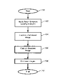
FIG. 3 is a flow chart of a process for determining strain; and
FIG. 4 is another flow chart of a process for determining strain.
Detailed Description of the Drawings
A system and method of determining strain uses a photoluminescent coating.
The luminescence of the coating is dependent on the strain of the coating.
When the
coating is applied to a structure the strain of the coating is due to the
strain in the
structure.
The photoluminescent coating is made of a polymeric binder and a
photoluminescent probe molecule. The invention exploits the two alternate
decay
mechanisms in the photoluminescent probe molecule; to detect any changes in
strain.
FIG. 1 is a schematic diagram of the energy states of a photoluminescent probe
molecule.

CA 02251735 1998-10-14
WO 97/39318 PCT/LTS97/03852
-3-
The photoluminescent probe molecule is excited 10 by a photon to
a higher energy state 12. This higher energy state 12 is a
metastable state and as a result the photoluminescent probe
molecule quickly decays back to its ground state 14. As shown in
FIG. 1, the photoluminescent probe molecule can either lose its
energy by a non-radiative decay 16 or by a radiative decay 18
mechanism. The radiative decay 18 results in a photon being
emitted causing the coating to luminesce. In the absence of strain
being applied to the coating there is a fixed relationship between
to the probability of the non-radiative decay 16 and the probability of
the radiative decay 18. When a strain is applied to the coating the
free volume available to the photoluminescent probe molecule is
reduced. This reduces the probability that the photoluminescent
probe molecule will decay by the non-radiative mechanism 16 and
thereby increasing the probability that the photoluminescent probe
molecule will decay by the radiative mechanism 18. As a result,
the areas under strain will be brighter. In the preferred
embodiment the polymeric binder adheres to a wide variety of
surfaces and is a polydimethyl siloxane (i.e., a silicone rubber). In
2o the preferred embodiment the photoluminescent probe molecule
can be excited with light in the visible spectrum and luminesces in
the visible spectrum. Examples of such photoluminescent probe
molecules are donor-acceptor substituted diarylethylenes.
FIG. 2 shows a system 50 that is capable of exploiting the
properties of the photoluminescent probe molecule to measure the
strain over the surface of a complex object. The system 50 has a
controller 52 that is coupled to a stimulating light source (excitation
light, stimulating light) 54, 56. The excitation lights 54, 56 are used
to raise the photoluminescent probe molecule to the excited state
12. Multiple excitation lights 54, 56 can be used to insure that all
surfaces of an object 58 are illuminated. The excitation lights 54,
56 are controlled by a signal from the controller 52 that turns on
the lights 54, 56 for a predetermined period of time. The controller
52 is also coupled to an image capturing device (electronic camera)
60, 62. In one embodiment the image capturing device 60, 62 is a

CA 02251735 1998-10-14
WO 97/39318 PG"TIUS97/03852
-4-
CCD (charge coupled device) camera. The controller 52 has an
image signal that determines when the image capturing device 60,
62 captures an image (picture) of the luminescence intensity of the
coating on the object 58. The controller 52 has a strain signal that
controls a device for placing stress 64 on the object 58. In the
embodiment shown in FIG. 1 the device for placing stress 64 is a
wind generator. A plurality of local strain gauges 66 transmit a
strain signal to the controller 52. In one embodiment a plurality of
temperature sensors are also placed on the object 58. The
1o temperature sensors can be co-located with the strain gauges. The
output signal of the temperature sensors is connected to the
controller.
In one embodiment the controller 52 has a plurality of
processing modules, including a digitizer (digitizing device) 68, a
calibration module 70, a temperature correction module 72. The
digitizer 68 is used to digitize an analog picture from the electronic
camera 54, 56 to form a digitized image. The calibration module 70
is used to convert the luminescence intensities of the images to
strain levels. The calibration module 70 uses the inputs from the
2o plurality of strain gauges 66 to form a conversion scale from
luminescence intensity to strain level. The temperature correction
module 72 adjusts the luminescence intensities for any changes in
luminescence due to changes in the surface temperature of the
object 58. This is necessary because the luminescence intensity of
the coating is affected by changes is temperature. In one
embodiment the temperature correction module 72 holds the
temperature constant during the tests so that the images are
captured at a single temperature.
FIG. 3 is a flow chart of a method for determining strain that
3o can be implemented by the system of FIG. 2. The process starts,
step 100, by applying the strain sensitive coating to the object at
step 102 to form a coated object (painted object). Next, an image of
the luminescence intensity of the object in an unstressed state is
captured, to form an unstressed image (unstressed picture) at step
104. At step 106 an image of the luminescence intensity while the

CA 02251735 1998-10-14
WO 97/39318 PCT/US97/03852
-5-
object is stressed is captured to form a stressed image (stressed
picture). The stressed image and the unstressed image are
compared at step 108 to determine the strain on the object, which
ends the process, step 110.
FIG. 4 is a flow chart of another embodiment of a method for
determining stress. The process starts, step 120, by painting the
object with the strain sensitive coating at step 122. This object is
then exposed to an excitation light for a predetermined period of
time at step 124. An image of the luminescence intensity of the
to painted object is captured to form an unstressed image at step 126.
The object is placed under stress at step 128. The stressed object is
exposed to the excitation light for a predetermined period of time
at step 130. Next, a stressed image of the luminescence intensity of
the stressed object is captured at step 132. Both the stressed image
z5 and the unstressed image are adjusted for pixel to pixel efficiency
variations at step 134. Next, a dark image is subtracted from both
images at step 136 to form a normalized stressed image and a
normalized unstressed image. The images are adjusted for
differences in surface temperature (temperature of an object) and
2o the luminescence intensities are calibrated to strain levels at step
138. In one embodiment the images are next aligned to each other
on a pixel by pixel basis to form a pair of aligned images. Next, the
ratios of the luminescence intensities of the two images are
calculated (luminescence intensity ratios) at step 140 to form a
25 ratio image (strain image). Finally the ratio intensities are
converted to strain levels on the ratio image at step 142. Thus
using this process the full field strain of a complex curved object
can be determined quantitatively.
While the invention has been described in conjunction with
3o specific embodiments thereof, it is evident that many alterations,
modifications, and variations will be apparent to those skilled in
the art in light of the foregoing description. Accordingly, it is
intended to embrace all such alterations, modifications, and
variations in the appended claims.

Representative Drawing
A single figure which represents the drawing illustrating the invention.
Administrative Status

2024-08-01:As part of the Next Generation Patents (NGP) transition, the Canadian Patents Database (CPD) now contains a more detailed Event History, which replicates the Event Log of our new back-office solution.

Please note that "Inactive:" events refers to events no longer in use in our new back-office solution.

For a clearer understanding of the status of the application/patent presented on this page, the site Disclaimer , as well as the definitions for Patent , Event History , Maintenance Fee  and Payment History  should be consulted.

Event History

Description Date
Inactive: Expired (new Act pat) 2017-03-13
Inactive: IPC from MCD 2006-03-12
Grant by Issuance 2003-11-18
Inactive: Cover page published 2003-11-17
Inactive: Final fee received 2003-08-26
Pre-grant 2003-08-26
Notice of Allowance is Issued 2003-02-28
Letter Sent 2003-02-28
Notice of Allowance is Issued 2003-02-28
Inactive: Approved for allowance (AFA) 2003-02-02
Amendment Received - Voluntary Amendment 2002-07-17
Inactive: S.30(2) Rules - Examiner requisition 2002-05-09
Amendment Received - Voluntary Amendment 2002-03-25
Inactive: Correction to amendment 2002-02-14
Amendment Received - Voluntary Amendment 2002-02-14
Inactive: S.30(2) Rules - Examiner requisition 2001-11-15
Amendment Received - Voluntary Amendment 2001-02-07
Amendment Received - Voluntary Amendment 1999-02-15
Inactive: First IPC assigned 1998-12-21
Classification Modified 1998-12-21
Inactive: IPC assigned 1998-12-21
Inactive: Acknowledgment of national entry - RFE 1998-12-09
Application Received - PCT 1998-12-04
All Requirements for Examination Determined Compliant 1998-10-14
Request for Examination Requirements Determined Compliant 1998-10-14
Application Published (Open to Public Inspection) 1997-10-23

Abandonment History

There is no abandonment history.

Maintenance Fee

The last payment was received on 2003-03-06

Note : If the full payment has not been received on or before the date indicated, a further fee may be required which may be one of the following

  • the reinstatement fee;
  • the late payment fee; or
  • additional fee to reverse deemed expiry.

Patent fees are adjusted on the 1st of January every year. The amounts above are the current amounts if received by December 31 of the current year.
Please refer to the CIPO Patent Fees web page to see all current fee amounts.

Owners on Record

Note: Records showing the ownership history in alphabetical order.

Current Owners on Record
UNIVERSITY OF FLORIDA
MCDONNELL DOUGLAS CORPORATION
Past Owners on Record
KIRK SCHANZE
MARTIN MORRIS
Past Owners that do not appear in the "Owners on Record" listing will appear in other documentation within the application.
Documents

To view selected files, please enter reCAPTCHA code :


To view images, click a link in the Document Description column. To download the documents, select one or more checkboxes in the first column and then click the "Download Selected in PDF format (Zip Archive)" or the "Download Selected as Single PDF" button.

List of published and non-published patent-specific documents on the CPD .

If you have any difficulty accessing content, you can call the Client Service Centre at 1-866-997-1936 or send them an e-mail at CIPO Client Service Centre.


Document
Description 
Date
(yyyy-mm-dd) 
Number of pages   Size of Image (KB) 
Representative drawing 1999-01-04 1 4
Abstract 1998-10-13 1 55
Description 1998-10-13 5 243
Claims 1998-10-13 5 125
Drawings 1998-10-13 4 54
Claims 2001-02-06 3 111
Description 2002-03-24 6 287
Claims 2002-02-13 3 108
Description 2002-07-16 6 285
Claims 2002-07-16 2 87
Notice of National Entry 1998-12-08 1 201
Courtesy - Certificate of registration (related document(s)) 1998-12-08 1 115
Courtesy - Certificate of registration (related document(s)) 1998-12-08 1 114
Commissioner's Notice - Application Found Allowable 2003-02-27 1 160
PCT 1998-10-13 7 311
Correspondence 2003-08-25 1 50