Note: Descriptions are shown in the official language in which they were submitted.
CA 02252019 2001-07-26
1
OPTICAL DENSITY MEASURING APPARATUS
BACKGROUND OF THE INVENTION
The present. invention generally relates to an
optical density measuring apparatus for securing
homogeneity of infrared measuring light which has a pair of
cells, one being a reference cell and the other being a
sample cell, in an infrared optical system thereof. The
apparatus finds an optical density of a sample on the basis
of a ratio between a pair of intensities of the infrared
measuring lights pas:~.ing through the pair of cells. The
invention particularly relates to the optical density
measuring apparatus t=herefor with a double-beam optical
system which transforms the infrared measuring light
emitted from a ligl-~t source into a parallel infrared
measuring light by a collimator lens, splits the parallel
measuring lights into two split parallel beams of light, and
makes the first beam of light and the second beam of light
pass through the reference cell and the sample cell,
respectively.
DESCRIPTION OF THE RELATED ARTS
A variety of optical density measuring
apparatuses have conventionally been provided. The optical
density measuring apparatuses are generally classified by
their optical paths, or beams of measuring light, into two
types: a type with a single-beam optical system and a type
CA 02252019 2001-07-26
2
with a double-beam optical system. The former type,
namely, the type with the single-beam optical system, which
has been conventionally popularized for a long time, has a
construction in which a cell is positioned in one beam of
light travelling from a light source to an optical
receiver. Throughout construction, the cell is filled up
preparatorily with pure water as a reference liquid, and
the quantity of transmitted light of the measuring light
that passes through 1=he pure water is detected beforehand
by the optical receiver. Then, after replacing the pure
water inside the cell with a sample, the quantity of
transmitted light of the measuring light that passes
through the sample :is detected, and the density of the
sample is found or calculated from the ratio between the
quantities of both of the transmitted measuring lights.
This type of optical density measuring apparatus
with the single-beam optical system, which employs the
single optical path cr beam of light, has an advantage that
an optical identicalness is maintained or assured at the
time of measuring tree reference cell and at the time of
measuring the sample cell, except for the density of the
sample inside the cell..
However, a blank calibration (zero-calibration)
of the optical density measuring apparatus belonging to
this type has to be periodically executed in order to guarantee
CA 02252019 2001-07-26
3
the identicalness the reof for a long term, and a user has to
take the trouble to replace the sample with pure water for
the calibration. As a result, this leads to the problem of
reduction in measurement efficiency of measuring the optical
density of the sample.
Also, an additional device or structure for the
replacement of the sample with the pure water is
indispensable, and this leads to another problem of high
cost of the apparatu:~.
J.0 Furthermore, in the event that even a small
amount of the sample remains inside the cell when replacing
the sample with the pure water at time of executing the
blank calibration, the accuracy of the blank calibration is
impaired.
1.5 Meanwhile, there has been suggested an apparatus
of the type with the single-beam optical system which
employs a cell called a cylindrical type variable-length
cell (refer to Japanese Laid-Open Patent Publication No. 4-
1556). This cylinderical type variable-length cell changes
20 the position of a pi:>t:on therein to allow the thickness of a
cylinder space, in which a samp:Le is put, to be changed into
a reference cell length and a sample cell length. This
apparatus has an advantage that it necessitates no pure
water for the blank calibration; however, it is very
~;5 difficult to maintain the piston at a predetermined position
CA 02252019 2001-07-26
4
with high accuracy for a long period. Therefore, the
apparatus has not yet. been put into practical use.
On the other hand, the apparatus of the type with
the double-beam optical system is intended to solve the
aforementioned problems of the type with the single-beam
optical system, thereby obviating the need to carry out the
blank calibration employing the pure water.
The type with the double-beam optical system
includes a type of apparatus in which a measurement light
1.0 emitted from a light source is directly split into two
optical paths or beams of ls.ght from the beginning, in
which a reference cell and a sample cell are positioned in
the first beam of light and the second beam of light,
respectively, in which identical samples are put in both of
1.5 the cells, and in which the lights that have passed through
the cells are received by an optical detector or optical
receiver (refer to Japanese Laid-Open Patent Publication No.
3-223654). This apparatus has an advantage that it
requires no pure water for blank calibration, and an
~:0 advantage that both of the cells are stationary (or fixed)
and are provided with no movable parts.
However, t:he apparatus directly splits the
measuring light from the light source into the two partial
lights (i.e. two beams of light) even though the light
2:5 source is identical.. Therefore, the homogeneity or
CA 02252019 2001-07-26
identicalness of the two diverged optical paths, or beams
of light, is not guaranteed at all. Therefore, a
calibration curve must be prepared and made every time the
light source is aged, or every time the light source itself
5 is changed. As is well known, the preparation and making
of the calibration curve is a troublesome undertaking
requiring many hours <~nd much burden.
Therefore, assuring the homogeneity, or
identicalness, of the optical paths, or beams of light, to
:LO be used for the measL,rement of both the reference cell and
the sample cell is absolutely necessary to improve the
accuracy of the measurement thereof.
As another conventional apparatus of the type
with the double-beam optical system, which seems to
:15 somewhat solve the aforementioned problem, there can be
enumerated an apparatus as disclosed in Japanese Laid-Open
Patent Publication No. 5-332933. The essential part of
this apparatus is sch~=_matically shown in Figs. 1 and 2.
This apparatus has an optical system including an
20 infrared light source "0", a shutter "S" for taking part of
the light out from the light source "0", a mask
"M" having two apertures "Ml" and "M2", a collimator
lens "L2", a reference cell "C1", a sample cell
"C2", an interference filter (not shown), a focusing
:?5 lens (not shown), and an optical receiver or optical
detector (not shown). In this optical system, an
CA 02252019 2001-07-26
6
infrared measuring light emitted from the light source "0"
passes limitedly thr«ugh a region of an opening "S1" of the
shutter "S" located ahead. In the figures, the opening "S1"
is located in an upper position.
In the fignares, the infrared measuring light that
has passed through the opening "S1" further passes through
the first aperture "M1" of the mask "M", the travelling
beam of the infrared measuring light is transformed into a
parallel beam of light by the collimator lens "L2," and
then the parallel beam of light passes through the
reference cell "C1".
On the other hand, when the opening "S1" of the
shutter "S" moves to a lower position (not shown), the
infrared measuring Eight emitted from the light source "0"
passes through the second aperture "M2" of the mask "M", the
travelling beam of_ the infrared measuring light is
transformed into a parallel beam of light by the
collimator lens "L2," and then the parallel beam of light
passes through the sample cell "C2" (a detailed description
about subsequent processing of the transmitted measuring
light is omitted below).
In the optical system of the apparatus shown in
Figs. 1 and 2, the two split parallel beams of light,
which are derived from one beam of light emitted forward
from the light source "0, " are used as a light that passes
CA 02252019 2001-07-26
7
through the reference cell "C1" and a light that passes
through the sample ce=L1 "C2", respectively, by employing at
least an identical optical component. Therefore, the
homogeneity, or identicalness, of both of the split parallel
beams of light is presumed to be guaranteed considerably.
However, if- a measurement with ultrahigh-accuracy
is desired, even thin> apparatus cannot realize a sufficient
homogeneity or iden~_icalness of the two split parallel
beams of light employed therein. The reason for this will
be described below with reference to Figs. 1 and 2.
It may be generally considered that, if an
identical light source is used, identical fluctuations arise
simultaneously in the two parallel beams of light with
respect to a fluctuation in light emission intensity of the
1.'p light source. However, strictly speaking, the light source
has a specified area with respect to the entrance pupil
diameter of the optical system. Therefore, improvement of
the measurement accuracy cannot be realized unless the
optical system is constructed by taking into consideration
the fact that the optical information of the intensity, and
so on, of the infrared measuring light emitted from each
luminous point constit=uting the specified area differs at
each luminous point.
The light source "O" shown in Figs. 1 and 2
2~~ includes a filament "O1" that serves as an illuminant. In
CA 02252019 2001-07-26
8
Fig. 1, the center of the filament "O1" having a specified
area, and the point= of center of symmetry of the two
apertures "M1" and "M~:~," are both located on an optical axis
"P." In this con struction, an infrared measuring light
emitted from the point of the center "02" of the filament
"01" is limited by the mask apertures "M1" and "M2," and
then the two split measuring lights are made to pass through
the collimator lens "L2" so that the two split measuring
lights are transformed into two split parallel beams of
light "B1." and "'EB?" symmetrical relative along the
optical axis "P." That is, in a certain measurement space
of the cell "C, " the beams of light "B1" and "B2" can be
regarded as lights with an identical quality.
On the other hand, the infrared measuring light
l:~ emitted from an end "03" of the filament "0l" is transformed
into two split parallel beams of light "D1" and "D2" in a
similar manner, as shown in Figs. 1 and 2. As is apparent
from the figures, the beams of light "D1" and "D2" are not
symmetrical relative to optical axis "P", and are
2c) unbalanced. That is, if a pair of apertures on the mask are
arranged on the basis of a mere simple conception that only
the symmetry o.f the apertures relative to the optical axis
is essential, then the two beams of light "D1" and "D2"
may pass through asymmetrical areas (i.e. areas not
2.'i symmetrical relative to the optical axis "P") of the
CA 02252019 2001-07-26
9
measuring space in which the cells "C1" and "C2" are
positioned.
A further problem may arise by a positional shift
of the filament "0l" when the light source "O" itself is
replaced by another one. Fig. 2 shows a state in which the
position of the fil.a:ment "0l" is shifted from the state of
Fig. 1. Fig. 2 illu~>t-rates a situation where an end "04" of
the filament "0l" is positioned on the center of the optical
axis "P". In this case, the other end "03" of the filament
"0l" is largely displaced from the center of the optical
axis "P." Therefore, the beams of light "D1" and "D2"
that have been limited by the mask apertures "M1" and "M2"
are more largely displaced or shifted from the optical axis
"P" in the measuring space.
Under an extreme situation, it is possible that
the beam of .Light "D2" that passes through the sample cell
"C2" may include almost none of the optical information on
the end "03" of the filament "O1."
Consequently, under such a situation, the two
beams of light have optical information with utterly
different qualities when the light source is replaced.
Therefore, the relation between the density and the
absorbance measured or calibrated on the basis of the
optical information prior to the replacement of the light
2.5 source becomes unusable, which in turn requires a remake (or
CA 02252019 2001-07-26
1~
reconstruction) of the calibration curve with respect to the
replaced new light source.
Another problem is a positional nonuniformity of
optical penetration characteristics of an interference
filter which is employed in this type of spectroscopic
apparatus. As a spectroscopic filter, to selectively allow a
specified wavelength to pass the filter, the interference
filter is simple, convenient and thus widely used. However,
its spectroscopic spectrum characteristics are not always
uniform depending c>n each interference filter. This
nonuniformity thereo:E is in connection with the problem
concerning a manufacturing process of a multilayer
deposition film, aTld even the spectroscopic spectrum
characteristics of a plurality of interference filters
1.5 manufactured through an identical manufacturing process have
variations in the peak wavelength and half width thereof.
Further, strictly ~~peaking, even in one filter, the
spectroscopic penetration spectrums are not necessarily the
same, depending on what part of the filter the light passes.
2~) Since the beam of light is single in the
aforementioned conventional apparatus with the
single-beam optical system, the positional nonuniformity of
the interference filter is similarly included both at the
sample measuring stage and at the reference measuring stage,
2_'i causing no such problem as described above. However, in
CA 02252019 2001-07-26
11
the case that the beam of light is split into parts and
that a difference is spectroscopic spectrum between both
the optical paths ~~ccurs, a fatal error arises in the
measurement result.
Therefore, how the positional nonuniformity of
the spectroscopic s~>ectrum is allowed to be uniformly
included in both of the beams of light is an important
technical object.
SUMMARY OF THE INVENTION
Accordingly, it is an object of the present
invention to provide an optical density measuring apparatus
in which the homogeneity or identicalness of the measuring
light is secured so that the optical information upon the
light source is uniformly included in the measuring space
about the optical axis, even if a fluctuation occurs in the
light source therein.
It is another object of the present invention to
provide the optical density measuring apparatus in which the
homogeneity or ident:icalness of the measuring light is
secured even if there is a positional nonuniformity in the
spectroscopic penetration spectrum of the interference
filter employed for the spectroscopic filter, so that the
nonuniformity of the penetration spectrum is uniformly
included in the measuring space about the optical axis.
In accomplishing these and other objects of the
CA 02252019 2001-07-26
12
present invention, there is provided an optical density
measuring apparatus comprising: a light source for emitting
an infrared ray as a measuring ray; an interference filter
for selecting a predetermined wavelength of the measuring
ray that passes through the interference filter; a first
lens for focusing the measuring ray emitted ,from the light
source on the interference filter; a collimator lens for
transforming the predetermined wavelength of the measuring
ray selected by the interference filter into a parallel
measuring ray; an opt=ical mask for splitting the parallel
measuring ray into a first split parallel measuring ray and
a second split parallel measuring ray; an optical shutter
for selectively pas:~ing one of the first split parallel
measuring ray and the second split parallel measuring ray; a
reference means which is provided in a light pass of the
first split parallel measuring ray; a sample cell which
is provided in a light pass of the second split parallel
measuring ray; an optical detector or optical receiver for
detecting the one of the first split parallel measuring ray
2~ which has passed thrc>ugh the reference means and the second
split parallel measuring ray which has passed through the
sample cell, in order to measure an optical density of a
sample in the sample cell; and a second lens for focusing
the one of the first split parallel measuring ray which has
2.'~ passed through the :reference means and the second s-Alit
CA 02252019 2001-07-26
13
parallel measuring ray which has passed through the sample
cell on the optical detector.
In the construction, the optical mask, for
example, can be a plate-shaped mask with a pair of apertures
for forming the first split parallel measuring ray and the
second split parallel measuring ray in which the pair of
apertures are juxtaposed symmetrically relative to an
optical axis.
In the construction, the measuring ray (or
measuring light) emitted from the light source is incident
upon the collimator ~_ens after the image of the light source
is formed on the interference filter as a spectroscopic
filter by means of the first lens; the light is made
parallel by the collimator lens; the parallel light is
divided or split into the first split parallel measuring ray
and the second split parallel measuring ray by means of the
optical mask; one of the first split parallel measuring ray
and the second split parallel measuring ray is selected by
the optical shutter; t:he one thereof selected by the optical
shutter is allowed to pass through either one of the
reference means and t:he sample cell; and the density of the
sample is measured and calculated on the basis of an amount of
light passing through the reference means, and an amount of
light passing through the sample cell.
According to the construction, the optical
CA 02252019 2001-07-26
14
information upon the light source, namely the predetermined
wavelength, selected by the interference filter, of the ray
of light that is emitted from each luminous point of the
light source is uniformly included in the first and second
split parallel measuring rays (i.e. in a pair of split
parallel beams of 7_ight).
That is, Clue information upon fluctuation of the
luminous point of the light source, and the positional
nonuniformity of the optical penetration characteristics of
the interference filter, are uniformly and equally included
in both of the beams of light. As a result, regarding the
positional change of the light source which has
conventionally been unable to be corrected, by correcting or
modifying the equation of operation by means of one-point
calibration based on t:he sample measurement, a high-accuracy
measurement can be achieved, thus making it unnecessary to
remake the calibration curve every time the light source is
replaced by another ~_ight source.
Also, according to the construction, the
spectroscopic spectra of both of the beams of light
coincide with each other. Therefore, the fluctuation
factors such as the variation in quantity of light emitted
from the light source, other than the optical density, is
completely cancelled in the reference optical path and the
measurement optical path (i.e. sample optical path).
CA 02252019 2001-07-26
In the above construction, the reference means can
include a reference cell. In this construction, it is
possible to provide the reference cell and the sample cell
as independent: separate cells, similar to the conventional
5 cells, in which pure water is put in the reference cell and
a sample is put in the sample cell, or in which a sample is
put in both the reference cell and the sample cell.
Preferably,. the optical density measuring
apparatus comprises a single cell housing by which the
10 reference means and the sample cell are constituted, in
which the cell housing has a first chamber and a second
chamber that penetrate to each other inside, in which a cell
length of the first chamber is shorter than a cell length of
the second chamber, and in which a reference cell of the
15 reference means corresponds to the first chamber while the
sample cell corresponds to the second chamber.
In this construction, the sample is concurrently
or simultaneously introduced into the first and second
chambers without demarcation. The quantity of light that
passes through the reference cell and the quantity of light
that passes through ~~:he sample cell, differ on the basis of
difference in their cell lengths.
According t=o the construction of the cell, the one
single cell is divided by the two chambers into the
reference cell and the sample cell; namely, they are not
CA 02252019 2001-07-26
16
mutually independent cells. The two cells have a
positional re.lation~>hip in which the two paraxial split
beams of light. penetrate or pass through the cells, and in
which both cells are infinitely close to each other. Also,
the sample is concurrently put into the two chambers, and
the sample is concurrently discharged from the two chambers.
This guarantees that the density of the sample in each of
the chambers is identical.
Also, in this construction, the cell is made of a
single member as described above. The measuring rays, or
the two split parallel beams of light (i.e. two split
parallel measuring rays or lights), travelling from the
light source to the optical receiver, pass through the
identical optical members. Therefore, the light absorption
characteristics of t:he optical substances other than the
density of the sample inside the reference cell chamber and
the sample cell chamber, are substantially identical in the
detected light that passes through the reference cell and in
the detected light that passes through the sample cell,
consequently allowing a higher accuracy of measurement to be
realized.
As a method to vary the length of one cell, it is
simple and convenient to provide an optical refraction
adjustment block, such as a block made of glass, in a cell
2.'~ housing having an identical thickness or length. Namely, an
CA 02252019 2001-07-26
l~
optical refraction index adjustment block, that has a
refractive index equal to or approximate to that of the
sample and has a lia~ht absorption characteristic different
from that of the sample, can be mounted (for example,
inserted) in a first portion of the cell through which the
aforementioned first splitting parallel beam of light
passes, and the cell length of the first portion thereof is
made shorter than the other second portion of the cell by
the thickness (i.e. by the length) of the optical refraction
index adjustment block.
In other words, the reference mear_s and the sample
cell can be constituted by mounting an optical refraction
adjustment block partially inside a cell housing with the same
length, in which a first chamber formed inside the cell
housing has a cell length that is shorter due to
intervention of the optical refraction adjustment block than
a cell length, generally equal to the same length of the
cell housing, of a :second chamber formed inside the cell
housing, and in which the optical refraction adjustment
2C) block has an index of refraction that is similar to an index
of refraction of the sample and the optical refraction
adjustment block has a light absorption characteristic that
is different from a :Light absorption characteristic of the
sample, and wherein a reference cell of the reference means
2~~ corresponds to the first chamber while the sample cell
CA 02252019 2001-07-26
18
corresponds to the second chamber.
According to this construction, the two pencils of
light penetrating or passing through the first portion and
the second portion c~f the cell (i.e. the light penetrating
the reference cell and the light penetrating the sample
cell), undergo substantially the same refraction and reach
the optical receiver via the second lens.
Therefore, amplification of the displacement (i.e.
shift or swerve) of the focusing point (i.e. image-forming
1.0 point) on the receiver due to aberration of the lens system
is effectively prevented, thus improving the measurement
accuracy.
In the construction, the reference means may be a
block made of glass.
Alternatively, the reference means may be an
atmosphere of air.
BRIEF DESCRIPTION OF THE DRAWINGS
These and other objects and features of the
present invention will become clear from the following
description taken in conjunction with a preferred embodiment
thereof and modifications to the embodiment with reference
to the accompanying drawings, in which:
Fig. 1 is a.n explanatory view of an essential part
of a double-beam optical system of a conventional optical
density measuring apparatus;
CA 02252019 2001-07-26
19
Fig. 2 is an explanatory view similar to Fig. 1;
Fig. 3 is <3n explanatory view of an essential part
of an optical system of an optical density measuring
apparatus according t:o a preferred embodiment of the present
invention;
Fig. 4 is an explanatory view showing an operation
of the optical system shown in Fig. 3, where a shutter and a
focusing lens shown in Fig. 3 are omitted;
Fig. 5 is an explanatory view similar to Fig. 4,
where the shutter anc~ the focusing lens shown in Fig. 3 are
omitted;
Fig. 6 is an explanatory view showing solid angles
of pencils, or beams, of light emitted from a light source;
Fig. 7 is a:n explanatory view similar to Fig. 6;
Fig. 8 is a front view of an optical mask and the
shutter which are employed in the optical system shown in
Fig. 3;
Fig. 9 is a. side view showing a cell, according to
a first modification, which can be alternatively employed in
the optical system shown in Fig. 3;
Fig. 10 is a. front view of the cell of Fig. 9;
Fig. 11 is a plan view of the cell of Fig. 9;
Fig. 12 is a view showing an essential part of a
cell, according to a second modification, which can be
2.5 alternatively employed in the optical system shown in Fig.
CA 02252019 2001-07-26
3; and
Fig. 13 is a view showing an essential part of a
cell, according to a third modification, which can be
alternatively employed in the optical system shown in Fig. 3.
5 DETAILED DESCRIPTION OF THE PREFERRED EMBODIMENT
Before a description of the preferred embodiment
and modifications thereto proceeds, it is to be noted that
like or corresponding parts are designated by like reference
numerals throughout the accompanying drawings.
10 First, re:~c=rring to Figs. 3 through 8, the
description is made below upon an optical density measuring
apparatus according to the preferred embodiment of the
present invention.
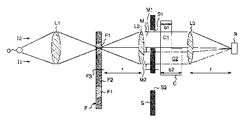
Fig. 3 s.s an explanatory view showing an optical
15 system of the optical density measuring apparatus of the
preferred embodiment_ of the present invention. Referring to
Fig. 3, a reference numeral "O" denotes an infrared light
source. A measuring light emitted from the light source "O"
travels through a measuring area to an infrared light sensor
20 or an optical receiver "R." Optical lenses "L1," "L2" and
"L3" are arranged in this order with a line connecting the
light source "O" to ~~ center of the optical receiver "R"
being as an optical axis, and other optical members are
arranged along the optical axis. The measuring light
2.~ emitted from the light source "O" reaches a focusing lens
CA 02252019 2001-07-26
21
"L1," and is then focused on an optical filter (interference
filter) "F" by the lens "L1". This filter "F"
comprises a rotation plate "F2" with a specified number
of interference filters "F1."
This interference filter "F1" selects only a
specified wavelength which is passed through and/or absorbed
by a component of tree sample to be measured. The rotation
plate "F2" has a predetermined number of interference
filters "F1" each of which has a particular light absorption
7.0 characteristic which is selected for each of predetermined
multiple kind of samples to be measured. The rotation plate
"F2" can rotate about an axis of rotation "F3." The
rotation plate "F2" is adjustably rotated about the axis
"F3" of rotation so that the light, emitted from the light
source "0" and passed through the focusing lens "L1," is
focussed on a selected interference filter "F1" of the
filter "F."
The infrarE=d measuring light that has penetrated
or passed through t:he interference filter "F1" diffuses
again and it reaches the collimator lens "L2." The
collimator lens "L2" is positioned ahead of the filter "F"
at a location at which the collimator lens "L2" is away from
the selected interference filter "F1" at a distance
corresponding to a focal length "f" of the collimator lens
"L2." With this arrangement, a beam of light incident on
CA 02252019 2001-07-26
22
the collimator lens "I~2" is sent forward as parallel light.
Just ahead of the collimator lens "L2" is arranged
an optical. mask "M." A front view of the mask "M" is shown
in Fig. 8. The mask "M" is provided with a pair of
apertures "M1" (whicl-~ is a "first aperture") and "M2" (which
is a "second aperture") so that a distance in diametrical
direction between a center (which is coincident with the
aforementioned optical axis) of_ the mask "M" and one of
the apertures "M1" ~~r "M2" i.s equal to a distance in
diametrical direction between the center of the mask "M" and
the other of the apertures "M1" or "M2." The first
aperture "M1" is an <aperture (i.e. diaphragm) for forming a
reference beam of. .Light; on the other' hand, the second
aperture "M2" is an aperture (i.e. diaphragm) for forming a
sample beam of light. That is, the parallel light that is
formed by the collimator lens "L2" and that corresponds to
the lens diameter, is split into a pair of small split
parallel beams of Light by the pair of apertures "Ml" and
"M2." In Fig. 8, the mask "M," the first and second
apertures "M1" and ~'M2," are shown by the broken lines,
respectively.
Just ahead of the mask "M" is arranged a shutter
"S." A front view of this shutter "S" is also shown in Fig.
8. This shutter "S" has a first opening "S1" and a second
2.~ opening "S2" which are located oppositely and asymmetrically
CA 02252019 2001-07-26
23
relative to a center "S3" of rotation thereof in its
diametrical direction. Fig. 8 shows a state in which the
first aperture "Ml" of the mask "M" and the first opening
"S1" of the shutter "S" are aligned with each other, and the
second aperture "M2" of the mask "M" is screened (or closed
or blocked) by the shutter "S".
Meanwhile, when the second opening "S2" of the
shutter "S" is aligned with the second aperture "M2" of the
mask "M", the beam of light passing through the second
aperture "M2" is sent forward, and the first aperture "M1"
is screened by the shutter "S."
A cell "C'," is arranged in a measuring area
provided ahead of 1=he shutter "S." This cell "C" is
prepared by integrating the reference cell "C1" with the
sample cell "C2" into one cell housing. The reference cell
"C1" is arranged on one side of a center thereof (aligned
with the optical a~~is), while the sample cell "C2" is
arranged on the other side thereof. A chamber constituting
the cell "C1" and a chamber constituting the cell "C2,"
communicate with each other, and the same sample (liquid) is
introduced into both of the chambers.
As shown in Fig. 3, the reference cell "C1" has a
cell length of "b1, " while the sample cell "C2" has a cell
length of "b2." The cell length of the latter is made
2.'~ sufficiently greater than that of_ the former. The reference
CA 02252019 2001-07-26
24
beam of light that has passed through the first aperture
"M1" of the mask "M" passes through the reference cell "C1,"
while the sample beam of light that has passed through the
second aperture "M2" of the mask "M" passes through the
sample cell "C2."
The aforementioned focusing lens "L3" is arranged
ahead of the cell "C," and the aforementioned optical
receiver "R" is arranged ahead of the focusing lens "L3" at
a location at which the receiver "R" is away from the
7.0 focusing lens "L3" with a distance corresponding to a focal
length "f" of the focusing lens "L3." With this arrangement,
the reference beam c>f light and the sample beam of light,
which are parallel light beams, are focused on the optical
receiver "R."
In comparison with the prior art illustrated in
Figs. 1 and 2, the a~>paratus of the preferred embodiment has
a significant feature that the measuring light is split into
the reference beam of light and the sample beam of light,
only after the light emitted from the light source "O" is
transformed into the parallel light by the collimator lens
"L2." It is to be noted that, according to the preferred
embodiment of the present invention, the measuring light is
not split into the reference beam of light and the sample
beam of light before the light emitted from the light
2.'~ source "0" is transformed into the parallel light by the
CA 02252019 2001-07-26
collimator lens "L2." The effect and function in accordance
with the construction of the preferred embodiment will be
described below in detail with reference to Figs. 4 through
7.
5 Before starting the explanation thereof, a
description is set oui= of a relation between the measurement
light and the density, the relation being derived from the
Lambert-Beer's Law. The relation is expressed by the
following equations ( 1. ) , ( 2 ) and ( 3 )
10 Ib = Il x exp (-a x b1 x c) x exp (-an x bn) x y . . . (1)
and
Is = I2 x exp(-a x b2 x c) x exp(-an x bn) x y ...(2)
where
I, I1, I2: quantity of light emitted from light source,
15 Ib: quantity of light received by the optical receiver
after passing through the reference cell,
Is: quantity of :Light received by the optical receiver
after passing through the sample cell,
a: light absorption coefficient,
20 b: cell length (cell thickness),
c: density,
an: 1_ight absorption coefficient of substance other
than component to be measured in the measuring optical
system (for example, light absorption coefficients of
2.'~ materials forming the cell, the filter and the lens, and
CA 02252019 2001-07-26
26
light absorption coefficient of dirt adhering upon them),
bn: thickness of substance other than component to be
measured in the measuring optical system, and
y: fluctuation _in detected intensity (fluctuation in
sensitivity of the optical receiver, and/or fluctuation in
quantity of light).
Based upon vhe above equations (1) and (2), the
density "c" can be obtained by t:he following equation (3):
c = -In ((Is/Ib) x (I1/I2))/(a x (b2 - b1)) ... (3)
Figs. 6 and 7 show fluctuations in solid angle of
the beams of light that are emitted from luminous points of
the light source and that are made incident on the
apertures "M1" and "M2" of the mask "M"; i.e., the figures
show the fluctuations in luminous flux of light or the
fluctuations in a unit light ray. That is, Figs. 6 and 7
show a state in which one end "03" of the filament "0l" is
located on the optical axis. Fig. 6 illustrates the solid
angles of the beams «f light emitted from the end "03" of
the filament "01", while Fig. 7 illustrates the solid
angles of the beams of light emitted from an end "04" of
the filament "0l". Furthermore, Figs. 6 and 7 do not show
the focusing lens "L1," the interference filter "F1" and
the collimator lens "L2" in comparison with Figs. 3 through
5.
As shown in Fig. 6, t=he solid angle "ail" of the
beam of light "E1" (i.e. beam of light being incident on
CA 02252019 2001-07-26
27
the aperture "M1") and the solid angle "~i2" of the beam of
light "E2" (i.e. bE~am of light being incident on the
aperture "M2"), both of which are emitted from the luminous
point "03" locating on the optical axis, are equal to each
other.
On the othE:r_ hand, as shown in Fig. 7, the solid
angle "~31" of the beam of light. "E3" which is emitted from
the luminous point "C>4" located away from the optical axis,
and the solid angle "~i2" of the beam of light "E4" which is
emitted from the same luminous point "04" located away from
the optical axis, are different from each other.
A filament of light source can be considered as
an aggregate of such multiple luminous points which are
located at different positions as described above.
Therefore, accurately considering the arrangement shown in
Fig. 3, the reference beam of light and the sample beam of
light do not exactly coincide with each other in terms of
light intensity etc. This means that the above "I1" and
"I2" do not always coincide with each other.
According to the present embodiment, the
measurement light emitted from the light source "0" having
a specified area is first focused on the interference
filter "Fl" of the optical filter "F", and the diffused
light from the body of rh~? interference filter "Fl" is transformed into
CA 02252019 2001-07-26
28
the parallel light by the collimator lens "L2." Thereafter,
the parallel light is split into the two split parallel
beams of light: the reference beam of light and the
sample beam of light=. Namely, the light emitted from each
luminous point of t:he light source passes through an
identical point of tlae interference filter "Fl" and reaches
the measurement space.
This will be described in more detail with
reference to Figs. 4 and 5, which corresponds to Figs. 1 and
2. Although Figs. :3 and 4 do not show the focusing lens
"L1, " the optical f:i lter "F" and the shutter "S", it is
possible to consider that the illustrated light source
filament "01" is actually superimposed on or overlaps with the
interference filter "Fl".
In Fig. 4, the center "02" of the filament "O1"
having a specified area, and the center of symmetry of the
two apertures "M1" a.nd "M2" of the optical mask "M," are
both located on the optical axis "P," which is similar to
the case explained above with reference to Fig. 1. With
this construction, t:he measurement light emitted from the
point of the center "G2" of the filament "0l" passes through
the interference filt=er "F1" of the filter "F," passes
through the collimator lens "L2" where the light is
transformed into the parallel light, and is limited by the
2!~ pair of mask apertures "M1" and "M2" so that the light is
CA 02252019 2001-07-26
29
split into two parallel beams of light "B1" and "B2"
symmetrical about the optical axis "P." That is, it can be
considered that the two parallel beams of light "B1" and
"B2" are the measuring lights with the same quality in the
measuring space in which the cell "C" is positioned.
Furthermore,. the measuring light emitted from the
end "03" of the filament "01" is transformed into the pair
of split parallel beams of light "D1" and "D2" in a similar
manner, as shown in Fig. 4. Namely, according to the
LO embodiment, the beams of light "D1" and "D2" are
superimposed on or overlap with the beams of light "8l" and
"B2" to become symmE~t~rical relative to the optical axis
"P," different from the conventional optical system
explained above with reference to Figs. 1 and 2. In other
:L5 words, the light from the luminous points "02" and "03" of
the light source are uniformly included in the two split
parallel beams of light.
In addit10I1, it can be appreciated that the
difference in spectroscopic characteristics, caused by
20 which part of the interference filter "F1" the light
passes, is also uniformly included in the two split
parallel beams of light in the same manner.
Also, the name thing can be said for the case
where the light source itself is replaced by another one
:?5 and the filament position is changed.
CA 02252019 2001-07-26
Explaining in more detail, Fig. 5, which
corresponds to Fig. 2, shows a state in which the filament
position is shifted from the state shown in Fig. 4.
Namely, the figure shows that the end "04" of the filament
5 "0l" is located on tree center of the optical axis "P." In
this condition, the end "03," opposite the end "04," of the
filament "O1" is largely displaced or shifted from the
center of the optical axis "P." However, the light emitted
from the luminous points "03" a.nd "04" is transformed into
10 the parallel light by the collimator lens "L2." Therefore,
the beams of light "D:I" and "D2" emitted from the luminous
point "04" coincide ca.ith the beams of light "B1" and "B2"
emitted from the luminous point "03." As a result, the
light emitted from the luminous points "03" and "04" is
15 uniformly included in the two split parallel beams of light
similar to the case shown in Fig. 4.
In the above arrangement, in the case that a mask
having an aperture of a very small opening is assumed and
in the case that a unit beam of light "DI" is defined with
20 regard to the beam c>f light emitted from each luminous
point of the light source, then the quantity of light
absorption is uniquely determined with respect to the
density in each split optical path.
Regarding the "I1" arid "I2," it is nothing but
a?5 the result indicating how many times (or how many beams of) the
CA 02252019 2001-07-26
31
unit beam of light "dI" have reached the optical receiver
"R" in the optical system. Therefore, the density can be
uniquely sought or found from the value of measurement, no
matter how the "I:L" and "I2" may be varied as a
consequence, by calculating the result in terms of the unit
beam of light.
Next, an explanation is made below upon a
concrete operation for obtaining the density from the
quantity of light in germs of the unit beam of light "DI,"
based upon the measurement values "I1" and "I2."
First., the use of this optical density measuring
apparatus is explained from the outset.
It is inii=Tally required to execute a blank
calibration. Accordingly, the measurement cell "C"
L5 (including the reference cell "C1" and the sample cell
"C2") is filled with pure water_ having a density of zero,
and then a value of Ib0/Is0 is measured. The measurer
cannot directly know the intensity of penetration (or
transmission) of the unit beam of light "DI." However, it
:?0 can be considered thai,;
"I1" = unit beam of light DI x a,; and
"I2" _ ~I x (3.
Therefore,
"I1" - (a/(3) x I2 can be obtained when I1/I2 is
25 converted into the unit beam of light.
CA 02252019 2001-07-26
32
Therefore, the aforementioned equation (3) can be
replaced as follows:
c = -In ( (Is/Ib) x (a,/~i) ) / (a x (b2 - b1) ) . . . (3' )
Then, K = ct/(3 is obtained by substituting into'the
equation (3') the measurement values of Ib0 and Is0
satisfying c - 0. From the relation, a calibration curve
including "K" can be formed, on the assumption that "K" is a
constant value.
Namely, the calibration curve is made from the
ratio between the quantities of light obtained by
multiplying the quan~~ities "4I1" and "0I2" of light that
penetrate the optical. paths of the standard (or reference)
unit beam of light t1I by "a," and "(3, " respectively. The
density is uniquely determined from the ratio between the
quantities "I1" and "I2" of the transmitted light.
Next., the case where the light source is replaced
by another one so th,~t the quantities of transmitted light
in the two split parallel beams of light are varied,
respectively is explained.
In this case, it is assumed that:
I1' - a' x ~I; and
I2' - ~3' x DI,
where "I1 "' and "I2 "' are new transmitted beams of
light, respectively.
2.'i I:n this situation, if measured signal
CA 02252019 2001-07-26
33
intensities "Ib "' and "Is "' directly applies to the above
equation (3'), then the measurement value becomes a value
which is different From the true value. For example, the
density does not become zero even when pure water is
measured, and a different value would be calculated or
obtained.
The reason why the values of "I1" and "I1"' become
different from each other is due to the difference in
quantity between the transmitted beams of light, and the
7_0 light absorption characteristics that the unit beam of
light receives, i.e. the quantities Il/a and I1'/a' of the
transmitted Eight, a re the same.
Therefore, under this condition, if the quantities
of light Ib0' and Is0' transmitted or penetrated through
pure water are new:Ly measured and substituted into the
aforementioned equatuons (1), (2) and (3'), then there can
be obtained the following equations:
Ib0' - ~I x a' x exp (-a x b1 x c) x exp (-an x bn) x y
where c = 0;
Is0' - DI x (3' x exp(-a x b2 x c) x exp(-an x bn) x y
where c = 0; and
c = -In ( (Is0' /Ib0' ) x (a' /~3' ) ) / (a x (b2 - b1) ) .
According to the above equations, the value of
a'/(3' can be obtained. And, if "K" in this state is
corrected to:
CA 02252019 2001-07-26
34
K ---- a' /(3 ' , then,
the density can be obtained by means of the calibration
curve including "K" that has previously been made, without
remaking the calibration curve. This means that the
measurement does not: receive any substantial influence, by
executing the calibration of pure water when the light
source is replaced. This also means an overcoming of the
fatal drawback of the conventional measuring apparatus of
the type with the double-beam optical system.
7_0 Next, the cell "C" is explained.
As described above, the apparatus of the present
embodiment employs a cell of the type in which an
identical sample is put in an identical cell housing.
Therefore, the densities of the samples to be put in the
reference chamber and in the sample chamber are, of course,
identical. The problem arising in connection with this
arrangement is a di~~placement (i.e. shift or swerve) of a
focus being formed on the optical receiver "R," which is
caused by a difference in refractive index (or index of
refraction) of lighv~ due to the difference between the
length of the reference cell and the length of the sample
cell. Namely, the difference in refractive index between
the two optical paths causes a difference between the
quantities of refractions of the two beams of light;
consequently, there anises a difference in positions on the
CA 02252019 2001-07-26
optical receiver "R" to which the beams of light reach via
the two cells, as a result.
The measurement accuracy and/or variations)
thereof of the optical receiver "R" is affected by a
5 positional nonuniformity that cannot be ignored, and it
becomes one of the .inhibiting factors in the measurement
accuracy. It is to be noted that this problem is mostly
solved by putting the cell in the path of the parallel light.
However, this displa cement amounts to about 0.2 mm with
1.0 respect to a difference of 10 mm in cell length for a
measurement wavelength of 1.5 ~m according to the present
embodiment. Therefore, the spot position of light collected
on the optical receiver "R" actually differs, depending on
the reference optical path or the measurement optical path.
15 Consequently, the reference accuracy cannot be satisfied for
a longer period of time, in a field of measurement use in
which its high accuracy is required. This is because the
lens in the optical system generates an aberration of the
transmitted light; more strictly explaining, this is because
20 the light that has passed the collimator lens "L2" includes
a component that is not parallel relative to the optical
axis "P". This aberration is a phenomenon that cannot be
avoided so long as a general-purpose lens is used in the
apparatus.
25 In order' to solve this problem, a first
CA 02252019 2001-07-26
36
modification of the cell shown in Figs. 9, 10 and 11 is
provided.
Namely, Fig. 11 is a plan view of the cell
according to the fi:r:~t modification which corresponds to the
drawing of Fig.3; Fig. 9 is a side view of the cell shown
in Fig. 11; Fig. is a front view of the cell shown
and 10 in
Fig. 11. This cell according to the first modification
"C"
has a sample inlet "C3" and a sample outlet "C4" at the
upper and lower portions of the cell housing, respectively.
Inside the cell housing is inserted a refractive index
adjustment block "A" having a refractive index identical or
approximate to that of the sample (liquid) inside.
That is, t:he cell length of the reference cell
"C1" is "b1, " while t:he cell length of the sample cell "C2"
is "b2." However, the housing of the reference cell "C1",
and the housing of the sample cell "C2," have the same
thickness as shown in Fig. 11, and "cell length b2 minus
cell length b1" is the thickness of the block "A."
Therefore, with this construction, the beam of
light that has passed through the reference cell and the
beam of light that. has passed through the sample cell,
generally undergo the same refraction of light.
A normal liquid sample (for example, a
semiconductor cleaning liquid) is mostly made of water
(refractive index of light: 1.32); therefore, a quartz glass
CA 02252019 2001-07-26
37
(refractive index of light: 1.45) can be selected as a
substance having a refractive index close to that of water.
On the other hand, if the sample is a food oil
(refractive index of light: 1.52), then BK7 glass
(refractive index of light: 1.51) is appropriate, as another
example.
A precondition that these blocks can be employed
in the apparatus is that the blocks have a light absorption
characteristic different from that of the object component
of the sample for they density measurement. By incorporating
the aforementioned quartz glass into the cell "C", the focal
position shift of 0.2 mm of the preceding example is
substantially reduced to a shift of not greater than 0.05
mm, thus solving the practical problem in connection with
this shift.
Furthermore, as a simpler cell construction, it is
also possible to provide a quartz glass block "C "' in place
of the reference cel7_ Cl, as shown in Fig. 12, as a second
modification of the cell.
2t) Alternatively, it is also possible to provide
atmospheric air "C"" .itself in place of the reference cell
C1, as shown in Fig. L3, as a third modification of the cell.
Although the present invention has been fully
described in connection with the preferred embodiment
2_'i thereof and modifications to the preferred embodiment with
CA 02252019 2001-07-26
38
reference to the accompanying drawings, it is to be noted
that various other changes and modifications are also
apparent to those skilled in the art. Such changes and
modifications are to be understood as included within the
scope of the present. invention as defined by the appended
claims unless they depart therefrom.