Note: Descriptions are shown in the official language in which they were submitted.
CA 02252283 1998-10-30
-1-
IMPROVEMENTS IN STORAGE AND DISPLAY DEVICES
The present invention relates to storage and presentation of multiple flat
information
carriers, for example disc-shaped information carriers such as optical discs,
especially
compact discs or CDs.
The CD has become the medium of choice in the music industry, rapidly
replacing vinyl
records, and the compact disc read only memory (CD-ROM) has become similarly
common in the electronics business. With the proliferation of CDs and CD-ROMs
and
the amount of information stored on them, there has come a need for storage
and display
of multiple discs.
Applicant is primarily concerned with collections or compilations of
associated CDs
aimed especially at the music listener, for example collections of classical
music
composed by famous composers. Previously, such collections have been
bedevilled by
the limited capacity of CDs which, using presently-available technology, each
carry
approximately 75 minutes of music. Accordingly, to present music representing
the life
of a prolific composer such as Beethoven, for example, numerous CDs would be
needed.
This presents a challenge in packaging and displaying such a large number of
CDs.
CDs and CD-ROMs are tropically packaged in a standard plastic 'jewel box',
rectangular
in shape and generally comprising thermoplastic moulded front and back panels
with
sides which co-operate to form a box. The front and back panels are normally
hinged
together along one edge and open like a book. The front panel snap-fits to the
back panel
- 25 in a closed position (described in US Patent No. 4535888).
A disc holder tray of moulded thermoplastic, also of a generally rectangular
shape, is
snap fitted into the bottom panel. The tray generally has a recessed area for
receiving a
CD, and a central circular array of resilient cantilevered fingers, arranged
radially and
3 0 pointing inwards to support the CD. Such packaging is usually designed to
hold only one
disc, although multiple CD packages are known (as described by US Patent No.
4709812), whereby a mid-section is created between the front and back panels,
comprising one or more further CD holders.
3 5 Although the jewel box provides an attractive appearance and broadly
adequate
protection of its contents, it does have many drawbacks. It is expensive to
manufacture
CA 02252283 1998-10-30
-2-
due to the requirements for thermoplastic moulding, and the brittle nature of
the plastics
used in its construction make it highly susceptible to breakage. The
cantilevered central
fingers are also prone to breakage with use, which renders support and
location of the
disc almost impossible. Most importantly, the jewel box is substantially
bulkier than the
CD itself, making the packaging of multiple discs heavy and inefficient. This
is of
considerable importance when transporting goods internationally.
Collections of discs are generally packaged as boxed sets of single or double
jewel boxes
which do not facilitate compact storage or easy access and display of the
discs
themselves. Every time one wishes to listen to a different CD in the
collection, one must
open the box of the CD just listened to, put that CD away, find and open the
next box,
take the new CD out, and so on. This inconvenience of use can detract from the
user's
listening pleasure.
Various attempts have been made to circumvent the problems highlighted above.
WO
95/26917 describes a CD container made from a single sheet of recyclable
material
having a first section with overlapping components forming pockets, and a
second
section of a similar construction. The second section is then folded over the
first section
to provide protective cover for the contents of the package. This document
teaches the
2 0 use of minimum, biodegradable materials to reduce volume and weight. The
series of
folds and gluing necessary to assemble the package described suggests the need
for
manual dexterity or complicated folding and gluing machinery, thus increasing
the cost
of manufacture. The document does not describe a method to prevent discs
falling out of
the pockets, which would potentially lead to damage of the fragile discs.
WO 94/04440 teaches the storage of a plurality of discs in a wallet-style
container. The
discs are held by central circular arrays thus suffering similar problems to
the jewel box.
As only t<vo discs can be displayed at any one time, this storage unit does
not overcome
the problem of displaying many discs at any one time.
With the demise of the vinyl record, EP 0238350 describes an adapter for
housing CDs
in sleeves for traditional long-playing vinyl records. The plastic adapter is
moulded with
a snug fit into a record sleeve, having a recess to accept a CD and a
projection which is
received by the central hole of a CD in a snap or press fit. This prior art
also suggests
3 5 that a combination of the central projection or stud and development of
the arcuate sides
of the recess could be used in combination to support the compact disc. This
requires
CA 02252283 2003-O1-27
-3-
intricate moulding, increasing costs and potentially adding bulk and weight to
the
adapter as well as hindering access to the disc.
Several methods have been described with respect to the visual aspect of
displaying
CDs. WO 94/27892 describes a method for including a disc-shaped object in a
greetings
card. The disc is supported by one or more slits, configured to create flaps
which cover
portions of the circumference of the disc. This method describes the display
of only one
disc although the display of more would be feasible. EP 0514156 teaches the
presentation of discs containing information about a certain person or
character, in
combination with graphical display of the said person or character on both the
disc and
packaging. Again, this document does not describe the display of a plurality
of discs,
with the main aim of the invention being the use of the disc and packaging as
collectable
playing cards.
Against this background of prior art, the present invention aims to provide a
way of
efficiently packaging many flat information Garners, with an emphasis on
compact discs.
The invention may be defined as a portable package for storing and/or
displaying a
plurality of circular information carriers each having a central spindle hole,
the package
comprising a flat backing panel and a plurality of support means each
associated with the
panel and adapted to support a respective one of the information carriers,
wherein each
support means comprises a pocket within the panel adapted to engage one side
of an
information Garner, and a boss mounted on the panel outside the pocket, the
boss being
adapted to engage in the central spindle hole to hold said side of the
information carrier
in engagement with the pocket in a tilted orientation with respect to the
panel, such that
the side of the information carrier opposed to the pocket is clear of the
panel.
This arrangement ensures secure location of the information carrier with
respect to the
panel, with the pocket and the boss acting in synergistic relationship to
minimize damage
to the information carriers and to make them easier to remove and replace.
To limit insertion of the information carrier into the pocket and thus to
ensure correct
CA 02252283 2003-O1-27
-4-
positioning with respect to the boss, the slit may be smaller than an overall
diameter of
the information carrier that the support means is adapted to accept. Further
or in the
alternative, the aforementioned plies or layers can be attached to one another
in a manner
that limits insertion of the information carrier into the pocket. In a
particularly compact
lapped arrangement, the plies or layers are suitably attached to one another
between the
pocket and the boss.
The support means of the package are preferably disposed in an array, and for
optimum
compactness may be positioned and adapted to hold the plurality of information
carriers
in a mutually lapped formation. In an elegant arrangement, the pockets and
bosses of
successive support means of the array alternate with one another and an
information
carrier supported by one support means of the array is also supported by
another,
1 S adjacent support means of the array. For example, an information Garner
supported by
one support means may also be supported by the boss of the adjacent support
means.
The invention also encompasses the package of the invention as defined above
and
having a plurality of information Garners supported on the support means.
CA 02252283 1998-10-30
-$-
In order that the invention may be more easily understood, reference will now
be made,
by way of example, to the accompanying drawings, in which:
Figure 1 is a plan view of a blank illustrating fold lines to create a
package;
Figure 2 is a plan view illustrating the arrangement of slits and bosses
relative to
each other on a backing panel of the package;
Figure 3 is an enlarged detailed plan view illustrating an arrangement of
slits and
bosses to give optimal overlap of discs in a preferred embodiment;
Figure 4 is a sectional view along line IV-IV of Figure 3 illustrating the
arrangement of pockets and bosses to give optimal overlap of discs in the
preferred embodiment;
Figure 5 is an enlarged detailed plan view illustrating a design on the
backing
panel with a disc removed;
Figure 6 is a view corresponding to Figure $ but illustrating the arrangement
with
the disc in place; and
Figure 7 is a plan view of a backing panel in a further embodiment of the
invention, with an arrangement of discs that do not overlap.
Referring initially to Figure 1, a blank 10 of cardboard is square in plan and
may be
folded along fold lines 11, 12 and 13 such that, when folded into a package,
the final
shape and size of the package is substantially the same as the slewe of a
traditional long-
playing vinyl record. To this end, the sides of the blank 10 in the
illustrated embodiment
3 0 are each approximately 630 mm such that the folded package is
approximately 310 mm
square.
The blank 10 is printed and varnished on one side only, thus reducing its
manufacturing
cost. It is then folded along fold line 11 which bisects the blank 10 to
create a two-ply
oblong having the printed and varnished surface appearing on both sides. The
plies are
glued together around their mutual periphery and also at specific internal
locations which
CA 02252283 1998-10-30
-6-
will be explained later. Further folds are then made along parallel mutually
spacers fold
lines 12 and 13 parallel to and equidistant from the short edges of the
oblong. This
creates a book-like package having a spine 14 defined by the spacing between
the fold
lines 12 and 13.
The spine 14 is wide enough to accommodate the thickness of the contents of
the
package; for example, when accommodating CDs, a spine 14 of about 7 mm in
width is
appropriate. Equally, a larger blank could be used and additional folds made
to create
leaves or pages on which to mount further information carriers or text. The
spine 14 also
provides space for indicia such as the name of the recording artist or
composer, to assist
in indexing when the package is stored on a shelf or storage rack with the
spine 14
exposed.
Folding the blank 10 in this way enables the package to be opened out flat
allowing
display of and access to its contents, in this instance a set of discs such as
CDs. The discs
are mounted onto and displayed upon t~~o flat backing panels which define the
major
inner faces of the package. Having regard to the folding arrangement outlined
above, it
will be clear that each backing panel is made up of two plies or layers of
cardboard, each
glued to the other.
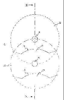
Referring now to Figure 2, one of the backing panels 15 has eight support
means 16 for
supporting eight discs, so that the package as a whole, which has two backing
panels,
can support sixteen discs. The support means 16 comprises an array of eight
slits 17 cut
in one, inner ply of the backing panel and a corresponding array of eight
circular bosses
18 stuck to the inner face of the inner ply. The bosses 18 are adapted
resiliently to
engage the central spindle hole of a CD (not shown), which hole is
approximately 15 mm
in diameter.
The arrays consist of two straight mutually parallel lines of slits 17 and
bosses 18,
3 o disposed side-by-side, each line consisting of four slits 17 and four
bosses 18. The slits
17 and bosses 18 of one line correspond in position to the slits 17 and bosses
18 of the
other line. Each line of slits 17 and bosses 18 is spaced sufficiently far
from the adjacent
edges 19 of the backing panel 15 that discs supported on the bosses 18 do not
overlap the
edges of the backing panel 15.
Each line is defined by the centres of its constituent bosses 18, which
alternate with the
CA 02252283 1998-10-30
_7_
slits 17. The slits 17 are disposed generally transversely with respect to,
and are
symmetrical about, that line. Each slit 17 has straight outer portions 20
angularly offset
with respect to each other and angled inwardly away from the associated boss
18. The
straight portions 20 are joined by a central arcuate portion 21 which curves
toward the
associated boss 18.
The bosses 18 of each line are spaced with a pitch of approximately 55 mm. It
will be
evident, therefore, that a row of standard CDs, which each have a diameter of
120 mm,
will overlap when engaged on the bosses 18. Reference is made to Figures 3 and
4 in
l0 this respect. The overlap is accommodated by an outer edge of an underlying
disc 22
engaged on a boss 18 being received in a pocket 23 whose opening is defined by
the slit
17 associated with that boss 18. Each boss 18 is glued to the backing panel 15
a specific
distance from its associated slit 17, such that locating the disc 22 in the
pocket 23 aligns
the central spindle hole in the CD with the boss 18.
The pockets 23, in turn, are defined between the plies 24 and 25 that form the
backing
panel 15; to this end, the plies 24, 25 are not glued to one another in the
areas
corresponding to the pockets 23 but they are glued to one another as shown at
26 around
the pocket 23. In particular, the plies 24, 2~ are glued together in the
region between
2 0 each boss 18 and its corresponding slit 17. The depth of insertion of a
disc 22 into a
pocket 23 is limited by this glued area and/or by the length of the slit 17
which is less
than the diameter of the disc 22, say 110 mm.
The central arcuate portion 21 of a slit 17 creates a flap 27 that facilitates
insertion of a
disc 22 into a pocket 23 and also helps to retain the disc 22 in the pocket 23
once
inserted.
Although a pocket 23 would by itself be sufficient temporarily to retain a
disc 22, the
associated boss 18 co-operates with the pocket 23 to locate and hold the disc
22 securely
3 0 in place on the backing panel 15. In particular, the boss 18 prevents the
disc 22 falling
out of the pocket 23 if the package is inverted or otherwise disturbed.
This synergy is also evident in the relationship of the pocket 23 to the boss
18;
specifically in that the pocket 23 holds a disc 22 mounted upon a boss 18 in a
tilted
3 5 disposition with respect to the plane of the backing panel 15. This
greatly facilitates
compact overlapping of the discs 22, as best shown in Figure 4. Tilting also
spaces the
CA 02252283 1998-10-30
_$_
discs 22 from one another and from the backing panel 15; this facilitates easy
removal of
the disc 22 by allowing a user to grasp the exposed major portion of the disc
22, for
example by hooking a finger or two under the exposed portion and placing a
thumb
against an exposed part of the boss 18 to lever the disc 22 off the boss 18.
The bosses 18 are made from flexible circular foam rubber pads which are glued
to the
inner face of the backing panel 15 and are each slightly wider than the
central hole of the
disc 22, such that resilient engagement takes place with the central hole in
use. A boss 18
made from a flexible material, such as foam rubber, rather than resilient
cantilevered
l0 fingers, removes the possibility of breakage and reduces production costs.
In the arrangement described, it will be noted from Figure 4 that one disc 22A
is
supported at its periphery in its tilted disposition by the boss 18 that
supports an
underlying disc 22B in the lapped arrangement. Tilting and lapping the discs
22 in this
way reduces the overall thickness of the package and enables many more discs
22 to be
fixed to the backing panel 15. It also minimises damage to the discs 22
through chafing
between discs 22 and/or their packaging and the transfer of grease, dirt etc.
from other
discs 22 in the same package. This is especially important when storing and
transporting
the discs 22. The lapped arrangement also lends a distinctive and pleasing
appearance to
the package, which is important for the purposes of display in retail
premises, in
advertisements, or at the buyer's home.
Figures 5 and 6 illustrate a further advantageous feature of the package,
namely printing
on the backing panel 15 of indicia 28 that corresponds to a design printed on
the non-
recordable face of a disc 22. The design on the disc 22 is duplicated on the
backing panel
15 in the area to be covered by the disc 22 when the disc 22 is properly
located in its
pocket 23, such that when the disc 22 is taken out of its pocket 23, the
design 28 on the
backing panel 15 is visible. This acts as a guide to the correct replacement
of the disc 22
after use, for example in a position corresponding to text or graphics printed
on the
3 0 backing panel 15 giving information on the content of that disc 22. This
is especially
useful when more than one disc 22 has been removed from the package;
otherwise, its
correct location would not immediately be evident.
Figure 5 shows the printing and positioning of pockets 23 and bosses 18
relative to the
design 28 on the backing panel 15, with no discs 22 in place. Two support
means 16 are
shown, namely those associated with die two uppermost discs 22 of an array.
Figure 6
CA 02252283 2003-O1-27
-9-
corresponds to Figure 5 but also illustrates the manner in which the printing
on the
backing panel 15 and disc 22 match. Both figures show how the uppermost pocket
23 of
the illustrated array duplicates the portion of the design on the disc 22
which would be
covered by the pocket 23 when the disc 22 is oriented correctly in the pocket
23. In this
way, the user can see the complete design on the disc 22 when the disc 22 is
located in
that pocket 23.
Referring finally to Figure 7, in a further embodiment of the invention a
backing panel
29 has support means 16 fox supporting five discs (not shown) in non-lapped
relation.
Four outer support means 16, each comprising a boss 18 and a slit 17 as
before, are
disposed in a square array and a fifth, central support means 16 is positioned
on the
intersecting diagonals of the square array.
The package of the present invention stores and displays its contents in a
protective,
lightweight and attractive manner, and is simple and cost-effective to
manufacture. The
contents are supported in a way that allows easy access and visibility, while
minimizing
the volume of the filled package.
Many variations are possible within the inventive concept. For example, it is
not
essential that foam bosses are used to locate a disc; indeed, traditional
arrangements of
resilient fingers can be used if they are acceptable despite their
disadvantages. Also,
whilst the preferred embodiment has been described with reference to the
support and
display of optical discs and in particular CDs, the present invention does not
preclude
use with other disc-shaped or otherwise flat information carriers.
The present invention may be embodied in other specific forms without
departing from
its essential attributes. Accordingly, reference should be made to the
appended claims
rather than to the foregoing specific description as indicating the scope of
the invention.