Note: Descriptions are shown in the official language in which they were submitted.
CA 022~2284 1998-10-30
6972
LINTEL
Field of the Invention
This invention relates generally to prefabricated, structural framing
members used in a broad range of construction applications and, more
particularly, to a lintel having a metal side plate.
Background of the Invention
Lintels are typically used as structural framing members over windows
and doors, as girders to support roof and floor trusses, and in other residential,
industrial, commercial and agricultural applications. Generally, lintels span the
distance between two spaced supports and carry structural loads, e.g., the weight
of the structure above the lintel.
Known lintels are frequently fabricated on-site from two pieces of nominal
"2xN" lumber, e.g., 2x10 or 2x12 lumber (hereinafter referred to as "chords"),
and one or more pieces of filler material, e.g., 1/2" thick plywood, of selectedlengths for the particular application. The filler material is sandwiched between
the chords, and then nails are driven through the chords and the filler material to
form a composite structural member. The filler material is usually required so
that the actual thickness of the composite lintel matches the width of the framing
members which support the lintel.
These known composite lintels generally have far more capacity and
utilize far more materials than n~cecs~ry for most applications in which they are
used. Furthermore, being solid, site-built members, such lintels are
time-consuming to make, heavy to carry, and labor-intensive to install.
Another known type of lintel is made partly of wood and partly of steel,
and is marketed under the tradename Trifold. The known Trifold lintel includes
a "]" shaped steel member having a center web portion, and integral flanges thatextend in the same direction from opposing side edges of the web portion. To
build a Trifold lintel, a wooden frame of desired size is constructed, and the steel
CA 022~2284 1998-10-30
6972
member web portion is nailed or screwed to, and completely covers, one side of
the wooden frame. One integral flange of the steel member extends over the top
surface of the wood frame, and the other flange extends over the bottom surface
of the frame. The Trifold lintel can then be installed, for example, over a
5 window or door.
Although the Trifold lintel is lighter and utilizes less unnecessary materials
than the composite lintels ~ c~-ssecl above, like such composite lintels, the Trifold
lintel is time-con~uming and labor-intensive to assemble because of the large
number of individually driven nails or screws that normally must be used to allow
10 the Trifold lintel to carry common roof, floor or girder loads. Further, because
the web portion covers the entire side of the wooden frame upon which it is
installed, it substantially impedes the application of siding and other materials to
that side of the lintel.
It would be desirable to provide a lintel which does not have signific~nt
15 unnecessary capacity and, therefore, wastes less materials than known composite
lintels. It would be desirable to provide a lintel which may be pre-fabricated in
a factory for delivery to a job site to elimin~te the time, expense and imprecision
associated with on-site assembly. It also would be desirable to provide a lintelwhich is relatively light weight to reduce shipping costs to the job site and to20 facilitate on-site h~n(lling, and to provide a lintel to which siding materials can
be readily nailed or screwed without predrilling.
Summary of the Invention
These and other objects may be attained by a lintel having a metal side
plate in accordance with the present invention. The metal side plate provides
25 many advantages including that waste is substantially reduced by elimin~ting
nnPcecs~ry extra capacity, and such side plate enables pre-fabrication of the
lintel in a factory for delivery to a job site. Use of the metal side plate alsoresults in a relatively light weight lintel, which reduces shipping costs to the job
site and facilitates on-site h~n~ling. In addition, with each of the embodiments
. CA 022~2284 1998-10-30
6972
of the subject lintel, siding materials can be readily nailed or screwed to the same
side of the lintel to which the metal side plate is attached~ without predrilling.
More particularly, and in an exemplary embodiment, a lintel constructed
in accordance with the present invention includes a generally rectangular wood
5 frame of a height, length and thickness substantially corresponding to the
dimensions of the opening in which the lintel is to be installed. The frame is
formed by connected first and second elongate chord members (e.g., nominal
"2xN" members) that extend in spaced, substantially parallel, overlying
relationship to each other.
The subject lintel also includes at least one generally rectangular metal
side plate having at least first and second spaced groupings of integrally formed
teeth extending from one side along opposite longihl-lin~l edges thereof. The first
and second teeth groupings respectively engage the first and second chords. The
metal side plate member has a width intermediate of the height of the frame and
the distance between the first and second chords, and is positioned so as to
overlap portions of coplanar side surfaces of the first and second chords on oneside of the frame, while leaving a sufficient portion of one of the coplanar side
surfaces exposed between its lower longit~l~lin:~l edge and the bottom edge of the
frame, to permit convenient fastener attachment of siding or other materials.
Many alternate embodiments of the subject lintel are contemplated, and
several are specifically disclosed. For example, in one alternate embodiment
generally intended for applications where the subject lintel may be required to
carry heavier loads, the frame is provided with one or more internal stiffening
members that are connected to and extend transversely between the first and
second elongate chords. With this embodiment, the metal side plate may also be
fabricated to include a third grouping of integral teeth spaced interm~ te of the
first and second groupings of teeth for engagement with the stiffening members.
In yet another embodiment of the subject lintel, a plurality of metal side
plates are provided at predetermined locations spaced lengthwise along at least
one side of the lintel frame to provide openings through which electrical,
. CA 022~2284 1998-10-30
6972 -
plumbing or other members may be conveniently passed without the need for
drilling or cutting the subject lintel. In addition, for applications where the
subject lintel may be required to carry extreme loads, metal side plates may be
installed on both inner and outer sides of the lintel frame.
S The subject lintel is a structural component capable of carrying substantial
loads which minimi7P.~ Imn~cess~ry materials, production costs and waste. The
lintel also lends itself to being prefabricated under factory conditions to reduce
assembly costs, and may be made with a generally hollow inner core to reduce
shipping costs. The hollow inner core also makes the lintel relatively light weight
and easy to handle on-site. Optionally, the hollow inner core may be filled,
preferably with a light weight material, to provide enh~nrecl thermal or sound
insulation performance. In addition, and in each of the various embodiments of
the subject lintel described above, a portion of the lintel frame underlying themetal side plate is exposed, enabling convenient attachment of siding or other
materials to the lintel.
Brief Description of the Drawings
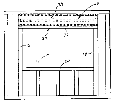
Figure 1 is a front view of a portion of a building frame for a window
including an exemplary embodiment of a lintel constructed in accordance with thepresent invention.
Figure 2 is a perspective partially exploded view of the lintel shown in
Figure 1.
Figure 3 is a schematic side view of the lintel shown in Figures 1 and 2.
Figure 4 is a perspective partially exploded view of an alternate
embodiment of a lintel constructed in accordance with the present invention.
Figure S is a front view of yet another embodiment of a lintel constructed
in accordance with the present invention and including two metal side plates
installed at locations spaced lengthwise along one side of the lintel frame to
provide an opening for the passage of heating, electrical, plumbing or other
materials.
. . CA 022~2284 1998-10-30
6972
Figure 6 is a rear view of the lintel shown in Figure 5.
Figure 7 is a schematic side view of a lintel constructed in accordance
with still yet another embodiment of the present invention and having metal sideplates installed on both sides of a lintel frame.
5 Detailed Description
Set forth below is a description of various embodiments of lintels
constructed in accordance with the present invention. The term lintel, as used
herein, refers to a structural framing member which spans the distance between
two spaced supports and carries structural loads, e.g., the weight of the structure
10 above the lintel. Lintels typically are utilized over windows and doors, as girders
to support roof and floor trusses, and in other residential, industrial, commercial
and agricultural applications.
One exemplary lintel application is illustrated in Figure 1, wherein a lintel
10 constructed in accordance with the present invention spans the width of a
window opening 12 formed by building framing members 16, 18, and 20. Lintel
10 is supported on framing members 16 and 18, and lintel 10 includes a wood
frame 22 and a metal side plate 24. Lintel 10 supports the weight of the structure
(not shown) above window opening 12. A portion 26 of wood frame 22
underlying metal side plate 24 is exposed, which enables convenient attachment
of siding or other materials to lintel 10.
Figure 2 is a perspective, partially exploded view of a portion of lintel 10
and more clearly illustrates generally rectangular wood frame 22 which has a
height, length and thickness substantially corresponding to the opening in whichlintel 10 is installed above the window opening 12 (not shown in Figure 2).
Frame 22 includes first and second elongate chords 28 and 30 which extend in
spaced, substantially parallel, overlying relationship to each other. Chords 28
and 30 provide inner and outer side pairs of spaced substantially coplanar surfaces
32A, 32B, 33A and 33B that respectively extend to top and bottom side edges of
frame 22. (Only top and bottom side edges 34 and 35 and coplanar surfaces 32A
. . CA 022~2284 1998-10-30
6972
and 33A on the inner side of the frame 22 are depicted in Figure 2.) Frame 22
also includes ~Lirr~ning members 36 that are connected to and extend transversely
between the first and second elongate chords 28 and 30. Stiffening members 36
are shown extending substantially vertically, or perpendicularly, to chords 28 and
5 30, although it is contemplated that the ~Lirrellillg members 36 could extend
diagonally, or angularly, relative to chords 28 and 30 without departing from the
intended scope of the present invention. Chords 28 and 30 and ~Lirrening
members 36 may be nominal "2xN" lumber, e.g., 2x4 or 2x6 lumber, of selected
lengths depending upon the specific application.
Lintel 10 also includes metal side plate 24 which has first and second
spaced groupings 38 and 40 of teeth. Teeth groupings 38 and 40 extend from one
side of the side plate 24 along opposite longit~ in~l edges thereof. The side plate
24 also includes a third grouping 42 of teeth spaced from and interm~ te of the
first and second teeth groupings 38 and 40. At least some teeth of the first
15 grouping 38 are engaged with the first chord 28, at least some teeth of the second
grouping 40 are engaged with the second chord 30, and at least some teeth of
third grouping 42 are engaged with the stiffening members 36.
Figure 3 is a schematic side view of lintel 10. As clearly shown in Figure
3, side plate 24 does not extend the full height of frame 22. Specifically, metal
20 side plate 24 has a width interm~ te of the height of frame 22 and the distance
between first and second chords 28 and 30, and is positioned so as to overlap
portions of each of the coplanar side surfaces of first and second chords 28 and30 on one side of frame 22, while leaving a sufficient space S1 (e.g., about oneinch) between its lower longitu~in~l edge and the bottom edge of frame 22 to
25 permit convenient fastener attachment of siding or other materials.
The metal plate 24 is preferably formed of ASTM A653, Grade 33 or
better galvanized sheet steel, and most preferably of such sheet steel with a
thickness between 14 and 24 gauge. Such sheet steel material is available in coil
form, in various widths, and the metal side plate 24 may be fabricated therefrom,
30 for example, by positioning a portion of the coil of the sheet metal material in a
- . CA 022~2284 1998-10-30
6972
conventional punch press and then simultaneously punching the spaced teeth
groupings 38, 40, and 42 to extend from one side of the portion of sheet metal
coil. The punched portion may then be cut off to the desired lintel length. The
teeth in the teeth groups 38, 40 and 42 may be of conventional construction such5 as the teeth of known metal connector plates used to form the joints of metal plate
connected wood trusses, but most preferably are of the type employed with the
MII 20 connector plate marketed by Mitek Industries, Inc. Side plate 24 can be
provided to prefabricators of the subject lintel in a roll or pre-cut form in various
lengths.
As also shown in Figure 3, connector plates 44 may be utilized on the side
of frame 22 opposite side plate 24. Connector plates 44 typically are located atthe interfaces between chords 28 and 30 and stiffening members 36, and such
connector plates 44 provide secure engagement between stiffening members 36
and chords 28 and 30.
To fabricate lintel 10, chords 28 and 30 and ~.Lirre~ g members 36 are
preferably positioned on an assembly table and jigged in the general outline of
frame 22, with connector plates 44 positioned under the interfaces of the chords28 and 30 and of the stiffening members 36 with their teeth pointed upwardly.
Side plate 24 is then located over the other or top side of the chords 28 and 3020 and stiffening members 36 so that at least a predetermined number of teeth offirst grouping 38 are over first chord 28, of second grouping 40 are over secondchord 30 and of third grouping 42 are over stiffening members 36, and so that
lower longit~ in~l edge of the plate 24 is spaced from the lower edge 35 of the
frame 22 a distance sufficient to allow convenient nail or screw attachment of
25 siding materials to the chord 30. This spacing is preferably about 1 inch. Side
plate 24 and the connector plates 44 are then engaged with chords 28 and 30 and
~.~irrenillg members 36 by a press or a roller in a manner known in the art.
Alternatively, the assembly may be assembled one side at a time and then flippedover for completion of the assembly process.
CA 022~2284 1998-10-30
6972
Lintel 10 provides the advantages of reducing waste and costs. For
example, lintel 10 has some excess weight bearing capacity, but lintel 10 does not
have excess capacity to the same extent of known composite lintels. Further, side
plate 24 reduces the amount of material required to fabricate lintel 10 and
therefore reduces the overall cost of lintel 10. In addition, lintel 10 is lightweight as compared to known composite lintels made of wood.
Lintel 10 also can be readily pre-fabricated at a factory and delivered to
a job site completely assembled. Therefore, a skilled carpenter would not be
required to make a lintel on-site, which enh~nres worker productivity.
Additionally, the above described metal side plate lintel 10 leaves sufficient space
between the side plate lower longit~l-lin~l edge and the bottom edge of the frame
to permit fastener attachment of siding or other materials to lintel 10 without
predrilling the side plate or splitting the lower chord 30 of the frame 22.
Figure 4 is a perspective view of an alternative embodiment of a lintel 50
constructed in accordance with the present invention. As compared to lintel 10,
lintel 50 typically would be utilized in lighter load applications. Components of
lintel 50 which are identical to components of lintel 10 are referenced in Figure
4 using the same reference numerals used in connection with lintel 10. As
compared to lintel 10, lintel 50 includes ~lirrenillg members 36 only at opposing
ends of frame 22 and the interm~Ai~te stiffening members are elimin~ted. In
addition, and with the elimin~rion of the interm~di~te ~lirr~ g members, third
grouping 42 of teeth in side plate 24 is elimin~ted The side plate 24 also is
illustrated with optional ~lirrenil1g ribs 52 which provide extra rigidity for plate
24.
Figures 5 and 6 are views of opposing sides of another embodiment of a
lintel 100 constructed in accordance with the present invention. Components of
lintel 100 which are identical to components of lintel 10 are referenced in Figures
5 and 6 using the same reference numerals used in connection with lintel 10.
Lintel 100 includes wood frame 22 and rather than a single metal side plate, a
30 plurality of metal side plates 102 and 104 are positioned at predetermined
. CA 022~2284 1998-10-30
6972
locations spaced lengthwise along at least one side of frame 22 to provide an
opening 106 through which electrical, plumbing or other members may be
conveniently passed without the need for drilling or cutting lintel. Side plates102 and 104 include first, second, and third groups 108, 110 and 112 of teeth toS engage chords 28 and 30 and ~tirre~ g members 36.
Figure 7 is a schematic side view of a lintel 150 constructed in accordance
with yet another embodiment of the present invention and having metal side
plates 24 installed on both sides of lintel frame 22. Components of lintel 150
which are identical to components of lintel 10 are referenced in Figure 7 using
the same reference numerals used in connection with lintel 10. Use of side plates
24 on both sides of frame 22 may be required in applications where lintel 150 isto carry extreme loads. In addition, light weight material can be located in thespaces (not shown in Figure 7) between ~irr~nillg members 36 before eng~ging
the second plate 24 to frame 22 so that such material is trapped within lintel 150.
Such use of material provides enh~n~ed thermal or sound insulation performance
for lintel 150.
The various lintel embodiments described above are structural components
capable of carrying substantial loads which minimi7~ llnnPcess~ry materials,
production costs and waste. Such lintels lend themselves to being prefabricated
under factory conditions to reduce assembly costs. The lintels also are relatively
light weight and easy to handle on-site. In addition, and in each of the variousembodiments of the subject lintel described above, a portion of the lintel frameunderlying the metal side plate is exposed, enabling convenient ~tt~chm~nt of
siding or other materials to the lintel.
From the prece~ling description of various embodiments of the present
invention, it is evident that the objects of the invention are ~tt~in~li Although the
invention has been described and illustrated in detail, it is to be clearly
understood that the same is intended by way of illustration and example only andis not to be taken by way of limitation. Accordingly, the spirit and scope of the
invention are to be limited only by the terms of the appended claims.