Language selection

Search

Patent 2252541 Summary

Third-party information liability

Some of the information on this Web page has been provided by external sources. The Government of Canada is not responsible for the accuracy, reliability or currency of the information supplied by external sources. Users wishing to rely upon this information should consult directly with the source of the information. Content provided by external sources is not subject to official languages, privacy and accessibility requirements.

Claims and Abstract availability

Any discrepancies in the text and image of the Claims and Abstract are due to differing posting times. Text of the Claims and Abstract are posted:

  • At the time the application is open to public inspection;
  • At the time of issue of the patent (grant).
(12) Patent Application: (11) CA 2252541
(54) English Title: DEVICE FOR EXTERNAL CLEANING OF SHIPS' HULLS
(54) French Title: DISPOSITIF POUR LE NETTOYAGE EXTERIEUR DE COQUES DE BATEAUX
Status: Deemed Abandoned and Beyond the Period of Reinstatement - Pending Response to Notice of Disregarded Communication
Bibliographic Data
(51) International Patent Classification (IPC):
  • B63B 59/08 (2006.01)
(72) Inventors :
  • WEBER, MANFRED (Germany)
(73) Owners :
  • MANFRED WEBER
(71) Applicants :
  • MANFRED WEBER (Germany)
(74) Agent: SMART & BIGGAR LP
(74) Associate agent:
(45) Issued:
(86) PCT Filing Date: 1997-04-25
(87) Open to Public Inspection: 1997-11-06
Examination requested: 1998-10-22
Availability of licence: N/A
Dedicated to the Public: N/A
(25) Language of filing: English

Patent Cooperation Treaty (PCT): Yes
(86) PCT Filing Number: PCT/DE1997/000834
(87) International Publication Number: DE1997000834
(85) National Entry: 1998-10-22

(30) Application Priority Data:
Application No. Country/Territory Date
296 07 426.8 (Germany) 1996-04-26

Abstracts

English Abstract


The invention relates to a cleaning system to avoid time-consuming and
expensive manual cleaning of ships'hulls (4). Said system comprises at least
one cleaning roller (2, 3) which can be driven to rotate and is rotatably
mounted in a rack (1). The roller structures of said cleaning rollers are at
least partially positioned below the water surface.


French Abstract

L'invention vise à éviter le nettoyage manuel, coûteux et long, de coques de bateaux (4) et a pour objet une installation de nettoyage comprenant au moins un rouleau nettoyeur (2, 3) pouvant être entraîné en rotation, monté rotatif sur un châssis métallique (1), le/ou les corps du/ou des rouleaux se trouvant au moins partiellement au-dessous de la surface de l'eau.

Claims

Note: Claims are shown in the official language in which they were submitted.

Device for external cleaning of ship's hulls
claims
1. Device for the external cleaning of ship's hulls,
c h a r a c t e r i s e d b y at least one cleaning
roller (2, 3) which can be driven to rotate, is rotatably
mounted in a rack (1) and whose roller structures are
positioned at least partially below the surface of the
water.
2. Device according to Claim 1, c h a r a c t e r i s e d
i n t h a t the cleaning rollers (2, 3) are designed as
brush rollers or loop brushes.
3. Device according to Claim 1 or 2, characterised
one or more roller pairs are provided,
where one of the individual rollers of a roller
pair is positioned on the starboard side and the other on
the port side of a ship.
4. Device according to Claim 3, c h a r a c t e r i s e d
i n t h a t a space is provided between the individual
rollers of a roller pair.
5. Device according to one of the Claims 1 to 4,
characterised i n t h a t the roller structures
and axles of the cleaning rollers are designed to be
flexible and adaptable to the shape of a ship's hull (4).
6. Device according to one of the Claims 1 to 5,
characterised i n t h a t the rack or racks (1)
for accommodating the cleaning rollers (2, 3) or roller
pairs are positioned in the water in fixed fashion.
7. Device according to one of the Claims 1 to 6,
characterised i n t h a t the cleaning rollers (2,

3) are mounted in movable fashion towards the side of the
ship and/or along the longitudinal direction of the ship.
8. Device according to one of the Claims 1 to 7, characterised
i n t h a t the angle of the roller
structures and roller axles to the vertical is adjustable.
9. Device according to one of the Claims 1 to 8,
characterised i n t h a t the drive motor(s) and
servomotor(s) (5, 6) for the cleaning rollers (2, 3) are
mounted above the surface of the water and are connected
to the rollers by drive arrangements, such as toothed
belts, bevel gears or the like.
10. Device according to Claim 9, c h a r a c t e r i s e d
i n t h a t the drive motor(s) and servomotor(s) are
designed as electric, hydraulic or pneumatic motors, and
are mounted both above and below the surface of the water.
11. Device according to one of the Claims 1 to 10,
characterised i n t h a t the roller structures
can be positioned against the ship's hull (4) by control
cylinders (9, 10).
12. Device according to one of the Claims 1 to 11,
characterised i n t h a t the drive motors or
servomotors and/or the control cylinders can be regulated or
controlled by sensors which respond to the size, shape or
position of the ship's hull (4).
13. Device according to Claim 12, c h a r a c t e r i s e d
i n t h a t the sensors are mounted on the control
cylinders.
14. Device for the external cleaning of ship's hulls,
c h a r a c t e r i s e d b y a circulating cleaning
belt which can be guided over the ship's hull (4) at
least partially below the surface of the water.

Description

Note: Descriptions are shown in the official language in which they were submitted.


CA 022~2~41 1998-10-22
Device for external cl~n; n~ of ship's hulls
i
The invention relates to a device for the external cleaning of
5 ship's hulls.
Over time, numerous forms of life, such as algae, crustaceans,
corals and the like, colonise the hulls of ships and yachts
below or at the waterline, depending on the nature of the body
10 of water. This may damage the hull material under certain cir-
cumstances, and always has a negative effect on the hydrody-
namic resistance of the ship's hull, thus impairing the per-
formance of the ship or, in the case of motor-driven ships,
resulting in increased fuel consumption.
For this reason, ships have heretofore been lifted out of the
water with hoisting gear about once a year and the accumulated
incrustation removed manually.
20 According to the prior art, in order to limit or prevent colo-
nisation of the ship's hull by living organisms, the hulls are
also treated regularly with a so-called "anti-fouling" coating
made of highly toxic substances, the inhibiting effect of
which subsides relatively quickly, however, due to the fact
25 that the substances used must also always be at least slightly
water-soluble in order to have a toxic effect on the organ-
isms. The use of toxic substances of this kind is problematic
from the standpoint of environmental protection.
30 The necessary manual cleaning of ship hulls is relatively
time-consuming and generates substantial costs. In addition,
it can usually only be carried out at expensive berths where
the corresponding hoisting cranes are available.
35 The invention is based on the task of designing a device for
the external cleaning of ship's hulls, with which cleaning
work of this nature can be performed more quickly and inexpen-
sively.

CA 022~2~41 1998-10-22
According to the invention, this task is solved by at least
one cleaning roller which can be driven to rotate, is rotata-
bly mounted in a rack and whose roller structures are posi-
tioned at least partially below the surface of the water.
In this context, the surface of the cleaning roller is pref-
erably designed such that, when rotating, it has an abrasive
effect on the accumulated layers of living organisms, but does
not risk damaging the hulls, which are generally made o glass
10 fibre-reinforced plastic (GRP). Possible alternatives include,
in particular, brush rollers, loop rollers, rollers with
roughened surfaces or rollers coated with grinding or abrasive
substances.
15 Although it is possible, in principle, to clean an entire hull
with a single cleaning roller, one or more roller pairs are
preferably provided, whose individual rollers are positioned
respectively on the starboard and port sides. The required
cleaning time can be drastically reduced in this way.
Standard ship hulls come to a relatively acute angle at the
bow, while they form a flat or obtuse angle at the stern. For
this reason, it can be expedient to mount consecutive pairs of
brushes at different angles.
A space is preferably provided between the individual rollers
of a brush pair, so that the keel or centre-board of a ship
can be drawn through it.
30 In order to be able to exert even pressure on all areas of the
hull, but also in order to be able to clean different hulls
with the same device, the roller structures and axles of the
cleaning rollers are preferably designed to be flexible and
adaptable to the hull shape. To this end, the axles can be
35 constructed of segments, for example, where the segments are
connected to one another via spring elements, for instance.
Axle and roller structures made of elastic plastic or rubber
materials are also suitable for this purpose.
.

CA 022~2~41 1998-10-22
The rack for supporting or accommodating the cleaning rollers
can be borne by floats, but is preferably positioned in the
water in fixed fashion, such as with the help of anchors. The
s ship is then pulled through the cleaning installation using a
windlass or the like, for example, where the forward speed can
be adapted to the thickness or nature of the contamination and
marine fouling.
10 On the other hand, it is also possible to firmly anchor the
ship and mount the cleaning rollers in movable fashion along
the longitudinal direction of the ship.
In order to adapt to different hulls, it is additionally ad-
15 vantageous to be able to move the cleaning rollers towards thehull in the rack. For this same reason, the angle of the
roller structures and roller axles to the vertical should be
adjustable.
20 The drive motors and the motors for adjusting the cleaning
rollers are preferably mounted above the surface of the water
and can be mounted, for example, on the rack for the cleaning
rollers. In order to drive the cleaning rollers, the drive mo-
tors are connected to them by standard drive arrangements,
25 such as toothed belts, bevel gears or the like, thus ensuring
that the drives, bearings and other movable parts, can func-
tion under water.
The drive motors or servomotors are preferably designed as en-
30 cased electric motors. Hydraulic or pneumatic motors can like-
wise be used. In the case of automatic cleaning installations,
the motors can be regulated or controlled by sensors, for ex-
ample, which respond to the size, shape and position of the
ship's hull.
In addition to cleaning rollers, circulating cleaning belts,
which are guided over the hull with the help of corresponding
drives, can also be used.

CA 022~2~41 1998-10-22
An example of the invention is illustrated in the drawings and
described in detail below based on the drawings. The drawings
show the following-
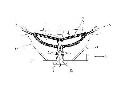
5 Fig. 1 A schematic illustration of a cleaning roller pairmounted on a rack in various positions for cleaning,
Fig. 2 A top view of one of the cleaning rollers according
to Fig. 1,
Fig. 3 A longitudinal section through a cleaning roller ac-
cording to Figs. 1 and 2, and
Fig. 4 A cross-section through a cleaning roller according
to Figs. 1 to 3.
The cleaning installation illustrated schematically in Fig. 1
consists of a rack 1, essentially mounted below the water
level, in which two driven cleaning rollers 2, 3 are mounted
20 perpendicular to the longitudinal direction of a ship's hull
4. Cleaning rollers 2, 3 are driven by motors 5, 6, which are
positioned above the water level and connected to electric,
pneumatic or hydraulic supply lines (not shown).
25 Cleaning rollers 2, 3 are elastically deformable along their
longitudinal axis and their upper ends are pivot-mounted on
side arms 7, 8 of rack 1. The ends of cleaning rollers 2, 3
located below the water level are borne by control cylinders
9, 10 which are of variable length and pivot-mounted on rack
30 1.
Figure 1 shows the position of cleaning rollers 2, 3 in the
top position when hull 4 is being driven in, i.e. at the bow,
and in the bottom position which they are in when cleaning the
35 widest point of the hull.
Rack 1 has a centre opening 11, through which, for example,
keel 12 of hull 4 can be pulled.

CA 022~2~41 1998-10-22
Figure 2 shows a top view of one of cleaning rollers 2, 3. In
particular, it clearly indicates the position of the control
cylinders.
Figures 3 and 4 illustrate the structure of the cleaning roll-
ers 2, 3 used. The roller consists of an elastically deform-
able core 13, which can be made of plastic or a flat coil
spring, for example. Individual brush segments 14, 15, 16 are
10 each mounted around core 13 in non-rotatable fashion and con-
nected to one another by elastically deformable spacers 17.
Outer surface 18 of brush segments 14, 15, 16 has bristle-like
cleaning elements 19 extending in the radial direction.

CA 022~2~41 1998-10-22
Device for external cl~n i n~ of ship's hulls
-;
List of reference numbers
1 Rack
2 Cleaning roller
3 Cleaning roller
4 Ship's hull
10 5 Motor
6 Motor
7 Side arm
8 Side arm
9 Control cylinder
15 10 Control cylinder
11 Opening
12 Keel
13 Core
14 Brush segment
20 15 Brush segment
16 Brush segment
17 Spacer
18 Outer surface
19 Bristle-like cleaning element

Representative Drawing
A single figure which represents the drawing illustrating the invention.
Administrative Status

2024-08-01:As part of the Next Generation Patents (NGP) transition, the Canadian Patents Database (CPD) now contains a more detailed Event History, which replicates the Event Log of our new back-office solution.

Please note that "Inactive:" events refers to events no longer in use in our new back-office solution.

For a clearer understanding of the status of the application/patent presented on this page, the site Disclaimer , as well as the definitions for Patent , Event History , Maintenance Fee  and Payment History  should be consulted.

Event History

Description Date
Time Limit for Reversal Expired 2004-04-26
Application Not Reinstated by Deadline 2004-04-26
Deemed Abandoned - Failure to Respond to Maintenance Fee Notice 2003-04-25
Letter Sent 2001-04-24
Reinstatement Requirements Deemed Compliant for All Abandonment Reasons 2001-04-11
Deemed Abandoned - Failure to Respond to Maintenance Fee Notice 2000-04-25
Classification Modified 1998-12-29
Inactive: IPC assigned 1998-12-29
Inactive: First IPC assigned 1998-12-29
Classification Modified 1998-12-29
Inactive: Acknowledgment of national entry - RFE 1998-12-14
Application Received - PCT 1998-12-11
Request for Examination Requirements Determined Compliant 1998-10-22
All Requirements for Examination Determined Compliant 1998-10-22
Application Published (Open to Public Inspection) 1997-11-06

Abandonment History

Abandonment Date Reason Reinstatement Date
2003-04-25
2000-04-25

Maintenance Fee

The last payment was received on 2002-03-26

Note : If the full payment has not been received on or before the date indicated, a further fee may be required which may be one of the following

  • the reinstatement fee;
  • the late payment fee; or
  • additional fee to reverse deemed expiry.

Patent fees are adjusted on the 1st of January every year. The amounts above are the current amounts if received by December 31 of the current year.
Please refer to the CIPO Patent Fees web page to see all current fee amounts.

Fee History

Fee Type Anniversary Year Due Date Paid Date
Basic national fee - small 1998-10-22
Request for examination - small 1998-10-22
MF (application, 2nd anniv.) - small 02 1999-04-26 1999-04-08
Reinstatement 2001-04-11
MF (application, 3rd anniv.) - small 03 2000-04-25 2001-04-11
MF (application, 4th anniv.) - small 04 2001-04-25 2001-04-25
MF (application, 5th anniv.) - small 05 2002-04-25 2002-03-26
Owners on Record

Note: Records showing the ownership history in alphabetical order.

Current Owners on Record
MANFRED WEBER
Past Owners on Record
None
Past Owners that do not appear in the "Owners on Record" listing will appear in other documentation within the application.
Documents

To view selected files, please enter reCAPTCHA code :


To view images, click a link in the Document Description column (Temporarily unavailable). To download the documents, select one or more checkboxes in the first column and then click the "Download Selected in PDF format (Zip Archive)" or the "Download Selected as Single PDF" button.

List of published and non-published patent-specific documents on the CPD .

If you have any difficulty accessing content, you can call the Client Service Centre at 1-866-997-1936 or send them an e-mail at CIPO Client Service Centre.

({010=All Documents, 020=As Filed, 030=As Open to Public Inspection, 040=At Issuance, 050=Examination, 060=Incoming Correspondence, 070=Miscellaneous, 080=Outgoing Correspondence, 090=Payment})


Document
Description 
Date
(yyyy-mm-dd) 
Number of pages   Size of Image (KB) 
Representative drawing 1999-01-12 1 12
Abstract 1998-10-21 1 51
Description 1998-10-21 6 201
Claims 1998-10-21 2 71
Reminder of maintenance fee due 1998-12-29 1 110
Notice of National Entry 1998-12-13 1 201
Courtesy - Abandonment Letter (Maintenance Fee) 2000-05-23 1 183
Notice of Reinstatement 2001-04-23 1 171
Courtesy - Abandonment Letter (Maintenance Fee) 2003-05-25 1 176
PCT 1998-10-21 14 443
Fees 1999-04-07 1 27
Fees 2001-04-10 1 37
Fees 2001-04-24 1 30
Fees 2002-03-25 11 481