Language selection

Search

Patent 2252572 Summary

Third-party information liability

Some of the information on this Web page has been provided by external sources. The Government of Canada is not responsible for the accuracy, reliability or currency of the information supplied by external sources. Users wishing to rely upon this information should consult directly with the source of the information. Content provided by external sources is not subject to official languages, privacy and accessibility requirements.

Claims and Abstract availability

Any discrepancies in the text and image of the Claims and Abstract are due to differing posting times. Text of the Claims and Abstract are posted:

  • At the time the application is open to public inspection;
  • At the time of issue of the patent (grant).
(12) Patent: (11) CA 2252572
(54) English Title: SHOCK-ABSORBING TOOL HANDLE
(54) French Title: MANCHE AMORTISSANT LES CHOCS POUR OUTILS
Status: Expired and beyond the Period of Reversal
Bibliographic Data
(51) International Patent Classification (IPC):
  • B25G 1/04 (2006.01)
  • A01B 1/00 (2006.01)
  • A01B 1/02 (2006.01)
  • B25G 1/01 (2006.01)
  • E01H 5/02 (2006.01)
(72) Inventors :
  • JACOBS, PAUL J. (United States of America)
  • SHAUD, RONALD J. (United States of America)
(73) Owners :
  • PAUL J. JACOBS
(71) Applicants :
  • PAUL J. JACOBS (United States of America)
(74) Agent: BORDEN LADNER GERVAIS LLP
(74) Associate agent:
(45) Issued: 2006-06-13
(86) PCT Filing Date: 1997-04-16
(87) Open to Public Inspection: 1997-10-30
Examination requested: 2002-01-16
Availability of licence: N/A
Dedicated to the Public: N/A
(25) Language of filing: English

Patent Cooperation Treaty (PCT): Yes
(86) PCT Filing Number: PCT/US1997/006523
(87) International Publication Number: WO 1997039858
(85) National Entry: 1998-10-19

(30) Application Priority Data:
Application No. Country/Territory Date
08/640,986 (United States of America) 1996-04-19

Abstracts

English Abstract


A shock-absorbing telescoping tool handle (2) is disclosed
having tubular, larger diameter proximal and a smaller diameter distal
portions (4, 6). An internal spring ( 14) between the handle portion
is compressed when the handle portions telescope toward each other.
Guide mechanism (26, 28) in the handle portions limits the extent
of sliding motion between the handle portions and prevents relative
rotation of the handle portions. One or more wipers (40) in the handle
portion wipes away any snow, water or debris on the distal portion
which could potentially enter the spring area.


French Abstract

L'invention concerne un manche (2) d'outil télescopique amortissant les chocs, qui possède une partie proximale ayant un diamètre plus important et une partie distale ayant un diamètre moins important (4, 6), de forme tubulaire. Lors du télescopage des deux parties du manche, le ressort interne (14), placé entre les deux parties, se comprime. Un mécanisme de guidage (26, 28), placé à l'intérieur des deux parties du manche, limite le déplacement des deux parties l'une par rapport à l'autre et ne leur permet pas de pivoter l'une par rapport à l'autre. Un ou plusieurs éléments de raclage (40), placés dans l'une des parties du manche, permettent d'enlever la neige, l'eau ou les détritus, qui risquent de pénétrer dans la partie où est situé le ressort.

Claims

Note: Claims are shown in the official language in which they were submitted.

-7-
CLAIMS
1. A shock-absorbing tool handle comprising:
a tubular proximal portion and a tubular distal portion;
the distal portion being adapted to receive a tool;
the proximal portion being larger in cross-section than the distal
portion and slidable over the distal portion in telescoping relationship
toward the tool;
a spring located within the handle, and compressible when the
portions telescope toward each other when force is applied in an axial
direction;
a first spring keeper in the distal portion and a second spring keeper
in the proximal portion; and
guide mechanism in the handle portions positioned to limit the
sliding motion between the portions and to permit the spring to be
compressed between the keepers when shock is applied to the handle.

-8-
2. Tool handle according to claim 1, wherein the first spring keeper
comprises a washer abutting a constriction in the distal portion.
3. Tool handle according to any one of claims 1-2, wherein the second spring
keeper
comprises a washer abutting a pin extending transversely of the proximal
portion.
4. Tool handle according to any one of claims 1-3, wherein the guide
mechanism comprises a slot in the distal portion through which passes a pin
fixed
in and extending transversely of the proximal portion.

-9-
5. A shock-absorbing tool handle comprising:
a tubular proximal portion and a tubular distal portion;
the distal portion being adapted to receive a tool;
the proximal portion being larger in cross-section than the distal
portion and slidable over the distal portion in telescoping relationship
toward the tool;
a spring located within the handle, and compressible when the
portions telescope toward each other when force is applied in an axial
direction;
a first spring keeper in the distal portion and a second spring keeper
in the proximal portion; and
guide mechanism in the handle positioned to limit the sliding motion
between the portions and to permit the spring to be compressed between the
keepers when shock is applied to the handle to prevent relative rotation of
the handle portions.

-10-
6. Tool handle according to claim 5, wherein the first spring keeper
comprises a washer abutting a constriction in the distal portion.
7. Tool handle according to any one of claims 5-6, wherein the second spring
keeper
comprises a washer abutting a pin extending transversely of the proximal
portion.
8. Tool handle according to any one of claims 5-7, wherein the guide
mechanism comprises a slot in the distal portion through which passes a pin
fixed
in and extending transversely of the proximal portion.

-11-
9. A shock-absorbing tool handle comprising:
a tubular proximal portion and a tubular distal portion;
the distal portion being adapted to receive a tool;
the proximal portion being larger in cross-section than the distal
portion and slidable over the distal portion in telescoping relationship
toward the tool;
a spring located within the handle, and compressible when the
portions telescope toward each other when force is applied in an axial
direction;
a first spring keeper in the distal portion and a second spring keeper
in the proximal portion; and
guide mechanism in the handle positioned to limit the sliding motion
between the portions and to permit the spring to be compressed between the
keepers when shock is applied to the handle; and
at least one wiper in the handle surrounding the distal portion and
engagable with the proximal portion to prevent the entry of contaminants
between the telescoping portions.

-12-
10. Tool handle according to claim 9, wherein the first spring keeper
comprises a washer abutting a constriction in the distal portion.
11. Tool handle according to any one of claims 9-10, wherein the second spring
keeper
comprises a washer abutting a pin extending transversely of the proximal
portion.
12. Tool handle according to any one of claims 9-11, wherein the guide
mechanism comprises a slot in the distal portion through which passes a pin
fixed
in and extending transversely of the proximal portion.

Description

Note: Descriptions are shown in the official language in which they were submitted.


CA 02252572 1998-10-19
WO 97/39858 PCT/US97/06523
SHOCK-ABSORBING TOOL HANDLE
Background of the Invention
This invention relates to shock-absorbing tool handles in general and, more
specifically, to handles for use with shovels and the like.
U.S. Patent 4,691,954 to Shaud discloses a shock-absorbing tool handle for
a snow shovel. The Shaud handle has two parts or portions which telescope
together and one part is joined to a detachable blade. Within the handle is a
spring
which compresses when the handle parts telescope together under axial load or
shock imparted from the blade striking an object hidden, for example, by the
snow. The compression of the spring reduces the shock impact to the user.
In the Shaud device, the handle parts are both tubular and the blade is
attached to the distal part or portion in conventional fashion, the proximal
portion
being the end which is gripped by the user. The proximal portion is narrower
in
diameter than the distal portion and slides into the larger distal tube. At
the
intersection of the two handle portions, water, snow and other debris can flow
downwardly into the larger diameter distal tube and, if allowed to collect,
adds
weight to the shovel, it could freeze or otherwise trap debris within the
handle.
With time, the spring could rust and other internal parts as well. It is,
accordingly, an object of this invention to provide a shock-absorbing tool
handle

CA 02252572 1998-10-19
WO 97/39858 PCT/US97/06523
-2-
which is not susceptible to the collection of snow, water or other debris
inside the
handle.
Summary of the Invention
The invention resides in a shock-absorbing tool handle comprising a tubular
proximal portion and a tubular distal portion. The distal portion is formed or
adapted to receive a tool such as the blade of a snow shovel or a spade. The
proximal portion is larger in cross-section than the distal portion and slides
over
the distal portion in telescoping relationship. The handle portions telescope
axially
toward each other when, for example, the blade or other tool meets resistance
such
as a ridge in a sidewalk being shoveled or a rock or any other hard object. An
internal spring is located between the handle portions and is maintained
between
keepers located within the respective handle portions. Guide mechanism is
located
in the handle portions to limit the amount of sliding motion and to permit the
spring to be compressed between the keepers when axial shock is applied to the
blade. The guide mechanism also serves to prevent relative rotation of the
handle
portions.
There is at least one annular wiper in the proximal portion surrounding the
distal portion to prevent the entry of contaminants between the telescoping
portions
in the area of the spring and to wipe contaminants from the distal portion
when the
handle telescopes.

CA 02252572 2005-07-13
-3-
One of the spring keepers comprises a constriction in one of the handle
portions supporting a washer and is illustrated as being located in the distal
portion. Another spring keeper comprises a washer abutting a pin extending
transversely of one of the portions herein illustrated as being the proximal
portion.
The guide comprises aligned slots on opposite sides of the distal portion of
the handle
through which~the extending pin extends.
The above and other features of the invention including various and novel
details of construction and combination of parts will now be more particularly
described with reference to the accompanying drawings and pointed out in the
claims. It will be understood that the particular shock-absorbing tool handle
embodying the invention is shown by way of illustration only and not as a
limitation of the invention. The principles and futures of this invention may
be
employed in varied and numerous embodiments without departing from the scope
of the invention.
Brief Description of the Drawinss
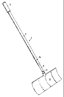
Figure 1 is a perspective view of a snow shovel embodying the present
invention.
Figure 2 is a portion of the handle of Figure 1 at the intersection of the
proximal and distal portions.
Figure 3 is a sectional view of the spring keeper taken along the line III-III
on Figure 2.

CA 02252572 1998-10-19
WO 97/39858 PCT/US97106523
-4-
Figure 4 is a sectional view of the line IV-IV on Figure 2 with the spring in
the expanded condition.
Figure S is a view similar to Figure 4 with the spring in compressed
position.
Figure 6 is a sectional view similar to Figures 4 and S disclosing a second
embodiment of the invention.
Detailed Description of the Invention
The handle, generally designated 2, comprises a proximal portion 4 and a
distal , portion 6. The distal portion is adapted to receive a tool such as a
snow
blade 8. The tool may be a space, pitchfork or any other equivalent tool. The
handle may be of any length. The blade may be attached by any convenient means
such as a pin 10. The proximal portion of the handle 4 is shown mounting an
optional hand grip 12. Both portions are tubular and the proximal portion 4 is
larger in cross-section than the distal portion and slidable over the distal
portion in
telescoping relationship. A spring 14 is contained within the handle portions
and is
compressible when the portions telescope toward each other. It is illustrated
is
being in the distal portion. A first spring keeper, best seen in Figure 4,
generally
designated 16 in the distal portion of the handle, comprises a washer 18 which
abuts an annular inwardly extending rib or constriction 20, formed by creating
an
annular indentation in the distal portion. A second spring keeper, generally
designated 22, comprises a washer 24 abutting a pin 26 which passes through
the

CA 02252572 1998-10-19
WO 97/39858 PCT/US97/06523
-5-
proximal tubular portion 4 and is slidably received in diametrically opposed
slots
28 formed in the tubular distal portion 6.
Before the spring 14 is compressed by axial force, that is, when it is moved
from the Figure 4 to the Figure 5 position, the pin normally resides at the
top 30
of the slots 28 since the spring is under a small amount of compression when
assembled. However, when the distal portion 6 of the handle strikes a hard
object
or is otherwise compressed, it moves from the Figure 4 to the Figure 5
position by
sliding into the proximal portion until the pin 26 abuts the bottom 32 of the
slots
28
The slots 28 serve an additional function of preventing relative rotation
between the proximal and distal portions of the handle. The pin 26 is fixed in
the
proximal portion 4 and at all times is engagable with one or the other of the
sidewalk of the slot limiting rotation to no more than the clearance between
the pin
26 and the slots 28.
Even though the proximal portion 4 of the handle is larger in diameter and
telescopes over the distal portion 6 and helps to prevent the entry of snow,
water
and debris into the area of the opening, at least one wiper 40 is provided in
the
handle to affirmatively wipe away the snow S. Whereas only one wiper is
necessary, two wipers are shown. The wipers comprising annular indentations 36-
38 formed in the proximal portion of the handle 4 creating an inwardly
extending
bulge 40 having essentially the same (but fractionally larger diameter than
the outer
diameter of the inner distal member 6). The wipers move downwardly of the

CA 02252572 1998-10-19
WO 97/39858 PCTIUS97/06523 __
-6_
distal portion with the annular bulges 40 wiping snow S and debris from the
distal
portion 6 as seen in Figure 5.
Figure 6 shows an alternative form comprising annular o-ring like members
44 retained in annular, outwardly extending, retaining recesses 46 in the
proximal
portion of the handle 4. The o-rings may be made of low friction plastic
material
such as DelrinT" or the like. Other possible materials for the wipers could be
felt,
for example, secured in the proximal portion 4 and engagable with the distal
portion 6 of the handle to wipe snow, rain and debris from the exposed distal
portion.

Representative Drawing
A single figure which represents the drawing illustrating the invention.
Administrative Status

2024-08-01:As part of the Next Generation Patents (NGP) transition, the Canadian Patents Database (CPD) now contains a more detailed Event History, which replicates the Event Log of our new back-office solution.

Please note that "Inactive:" events refers to events no longer in use in our new back-office solution.

For a clearer understanding of the status of the application/patent presented on this page, the site Disclaimer , as well as the definitions for Patent , Event History , Maintenance Fee  and Payment History  should be consulted.

Event History

Description Date
Time Limit for Reversal Expired 2015-04-16
Letter Sent 2014-04-16
Letter Sent 2012-09-24
Inactive: Single transfer 2012-09-11
Inactive: Payment - Insufficient fee 2007-05-08
Inactive: Payment - Insufficient fee 2007-04-12
Grant by Issuance 2006-06-13
Inactive: Cover page published 2006-06-12
Pre-grant 2006-03-17
Inactive: Final fee received 2006-03-17
Inactive: IPC from MCD 2006-03-12
Notice of Allowance is Issued 2005-09-20
Letter Sent 2005-09-20
Notice of Allowance is Issued 2005-09-20
Inactive: Approved for allowance (AFA) 2005-09-08
Amendment Received - Voluntary Amendment 2005-07-13
Inactive: S.29 Rules - Examiner requisition 2005-01-13
Inactive: S.30(2) Rules - Examiner requisition 2005-01-13
Letter Sent 2002-02-08
Request for Examination Requirements Determined Compliant 2002-01-16
All Requirements for Examination Determined Compliant 2002-01-16
Request for Examination Received 2002-01-16
Inactive: Entity size changed 2000-01-20
Inactive: Correspondence - Formalities 2000-01-11
Inactive: Cover page published 1999-11-22
Inactive: Single transfer 1999-02-09
Inactive: IPC assigned 1999-01-04
Inactive: First IPC assigned 1999-01-04
Inactive: IPC assigned 1999-01-04
Classification Modified 1999-01-04
Inactive: Courtesy letter - Evidence 1998-12-16
Inactive: Notice - National entry - No RFE 1998-12-15
Application Received - PCT 1998-12-11
Amendment Received - Voluntary Amendment 1998-10-19
Small Entity Declaration Determined Compliant 1998-10-19
Application Published (Open to Public Inspection) 1997-10-30

Abandonment History

There is no abandonment history.

Maintenance Fee

The last payment was received on 2006-04-03

Note : If the full payment has not been received on or before the date indicated, a further fee may be required which may be one of the following

  • the reinstatement fee;
  • the late payment fee; or
  • additional fee to reverse deemed expiry.

Please refer to the CIPO Patent Fees web page to see all current fee amounts.

Fee History

Fee Type Anniversary Year Due Date Paid Date
Basic national fee - small 1998-10-19
Registration of a document 1998-10-19
MF (application, 2nd anniv.) - standard 02 1999-04-16 1999-03-05
2000-01-11
MF (application, 3rd anniv.) - standard 03 2000-04-17 2000-03-07
MF (application, 4th anniv.) - standard 04 2001-04-16 2001-03-14
Request for examination - standard 2002-01-16
MF (application, 5th anniv.) - standard 05 2002-04-16 2002-03-19
MF (application, 6th anniv.) - standard 06 2003-04-16 2003-03-25
MF (application, 7th anniv.) - standard 07 2004-04-16 2004-03-25
MF (application, 8th anniv.) - standard 08 2005-04-18 2005-04-04
Final fee - standard 2006-03-17
MF (application, 9th anniv.) - standard 09 2006-04-17 2006-04-03
MF (patent, 10th anniv.) - standard 2007-04-16 2007-03-30
2007-07-08 2007-05-22
MF (patent, 11th anniv.) - small 2008-04-16 2008-03-31
MF (patent, 12th anniv.) - small 2009-04-16 2009-03-30
MF (patent, 13th anniv.) - small 2010-04-16 2010-03-30
MF (patent, 14th anniv.) - small 2011-04-18 2011-03-30
MF (patent, 15th anniv.) - small 2012-04-16 2012-04-05
Registration of a document 2012-09-11
MF (patent, 16th anniv.) - small 2013-04-16 2013-04-16
Owners on Record

Note: Records showing the ownership history in alphabetical order.

Current Owners on Record
PAUL J. JACOBS
Past Owners on Record
RONALD J. SHAUD
Past Owners that do not appear in the "Owners on Record" listing will appear in other documentation within the application.
Documents

To view selected files, please enter reCAPTCHA code :


To view images, click a link in the Document Description column. To download the documents, select one or more checkboxes in the first column and then click the "Download Selected in PDF format (Zip Archive)" or the "Download Selected as Single PDF" button.

List of published and non-published patent-specific documents on the CPD .

If you have any difficulty accessing content, you can call the Client Service Centre at 1-866-997-1936 or send them an e-mail at CIPO Client Service Centre.


Document
Description 
Date
(yyyy-mm-dd) 
Number of pages   Size of Image (KB) 
Representative drawing 1999-11-18 1 4
Claims 1998-10-20 6 110
Cover Page 1999-11-18 1 42
Abstract 1998-10-19 1 43
Description 1998-10-19 6 189
Claims 1998-10-19 6 105
Drawings 1998-10-19 2 75
Description 2005-07-13 6 188
Claims 2005-07-13 6 97
Representative drawing 2006-05-19 1 4
Cover Page 2006-05-19 1 36
Reminder of maintenance fee due 1998-12-17 1 110
Notice of National Entry 1998-12-15 1 192
Courtesy - Certificate of registration (related document(s)) 1999-03-10 1 117
Reminder - Request for Examination 2001-12-18 1 118
Acknowledgement of Request for Examination 2002-02-08 1 178
Commissioner's Notice - Application Found Allowable 2005-09-20 1 161
Notice of Insufficient fee payment (English) 2007-05-08 1 92
Courtesy - Certificate of registration (related document(s)) 2012-09-24 1 102
Maintenance Fee Notice 2014-05-28 1 170
PCT 1998-10-19 6 242
Correspondence 1998-12-16 1 30
Correspondence 2000-01-11 1 27
Fees 2000-01-11 1 30
Correspondence 2006-03-17 1 29