Language selection

Search

Patent 2252608 Summary

Third-party information liability

Some of the information on this Web page has been provided by external sources. The Government of Canada is not responsible for the accuracy, reliability or currency of the information supplied by external sources. Users wishing to rely upon this information should consult directly with the source of the information. Content provided by external sources is not subject to official languages, privacy and accessibility requirements.

Claims and Abstract availability

Any discrepancies in the text and image of the Claims and Abstract are due to differing posting times. Text of the Claims and Abstract are posted:

  • At the time the application is open to public inspection;
  • At the time of issue of the patent (grant).
(12) Patent Application: (11) CA 2252608
(54) English Title: RADIATION HEATER
(54) French Title: ELEMENT DE CHAUFFAGE A CHALEUR RAYONNANTE
Status: Deemed Abandoned and Beyond the Period of Reinstatement - Pending Response to Notice of Disregarded Communication
Bibliographic Data
(51) International Patent Classification (IPC):
  • F24C 15/22 (2006.01)
  • F24D 5/08 (2006.01)
(72) Inventors :
  • KEMNA, STEFAN (Germany)
(73) Owners :
  • STEFAN KEMNA
(71) Applicants :
  • STEFAN KEMNA (Germany)
(74) Agent: SWABEY OGILVY RENAULT
(74) Associate agent:
(45) Issued:
(86) PCT Filing Date: 1997-04-18
(87) Open to Public Inspection: 1997-10-30
Availability of licence: N/A
Dedicated to the Public: N/A
(25) Language of filing: English

Patent Cooperation Treaty (PCT): Yes
(86) PCT Filing Number: PCT/EP1997/001951
(87) International Publication Number: WO 1997040319
(85) National Entry: 1998-10-20

(30) Application Priority Data:
Application No. Country/Territory Date
196 15 770.6 (Germany) 1996-04-20

Abstracts

English Abstract


The invention relates to a radiation heater with a radiant tube surrounded by
a housing which has a reflector region guiding the heat radiation downwards.
The radiation heater can also be used in low spaces due to the fact that the
structure of the upper reflector region and/or lateral reflector regions
adjacent thereto and/or radiation surfaces of the radiant tube is such that
the heat radiation emerging from the housing has a distribution curve lowered
at the centre below the housing and raised in relation thereto on both sides.


French Abstract

L'invention concerne un élément de chauffage à chaleur rayonnante comportant un tube radiant entouré d'un boîtier qui présente une zone de réflecteur dirigeant le rayonnement thermique vers le bas. Cet élément de chauffage à chaleur rayonnante peut être utilisé même dans des locaux de faible hauteur car la zone supérieure du réflecteur et/ou les zones latérales du réflecteur adjacentes à la zone supérieure et/ou les faces de rayonnement du tube radiant sont conçues de sorte que le rayonnement thermique sortant du boîtier présente une courbe de répartition abaissée au centre sous le boîtier et élevée de part et d'autre de cette zone centrale.

Claims

Note: Claims are shown in the official language in which they were submitted.

1. Radiant heat heater with a housing (9) that h lateral reflector areas (2) and that at least
partially surrounds at least one radiant tube (8), that features an upper reflector area (1) that
deflects the radiating heat downward and is open at the bottom for the radiation of heat,
whereby the radiating heat that leaves the housing (9) has a distribution curve (a, b) that has a
shape that is depressed in the center under the housing (9) and on both sides is relatively
raised,
characterized by the fact
that the radiant tube (8) is arranged between the lateral reflector areas (2) in such a way that
their lower edges are positioned lower than the underside of the radiant tube (8).
2. Radiant heat heater according to claim 1,
characterized by the fact,
that the lateral sections of the radiating surface (4) are larger in cross section than the upper
or lower sections.
3. Radiant heat heater according to claim 3,
characterized by the fact,
that the cross seection of the radiant tube (8) is trapezoidal in shape, with a base positioned on
top or on the bottom, an oval with the larger diameter aligned vertically, a traingle with a
base that is on top or on the bottom, or a rectangular shape with vertically directed
longitudinal sides.
4. Radiant heat heater according to one of the previous claims,
characterized by the fact,

that the radiant tube has a selective coating (5) at least in sections.
5. Radiant heat heater according to one of the previous claims,
characterized by the fact,
that a reflecting lower reflector element (3) is arranged under the radiant tube (8).
6. Radiant heat heater according to claim 5,
characterized by the fact,
that the lower reflector element (3) features lateral deflection surfaces that deflect the
impacting heat radiation essentially symmetrically toward the sides.
7. Radiant heat heater according to claim 5,
characterized by the fact,
that the lower reflector element (3) is designed as a horizontal strip that reflects the impacting
radiation.
8. Radiant heat heater according to one of the previous claims,
characterized by the fact,
that the lateral reflector areas (2) are directed vertically.
9. Radiant heat heater according to one of the previous claims,
characterized by the fact,
that the reflector areas (2) are designed as vapor plated glass strips.

10. Radiant heat heater according to one of the previous claims,
chartacterized by the fact,
that the upper reflector area (1) in cross section features sections that drop off obliquely on
both sides toward the edge, or are curved.

Description

Note: Descriptions are shown in the official language in which they were submitted.


CA 02252608 1998-10-20
.~
WO 97/40319
R~dia~lt heat heater
The invenhon relates to a radiant heat heater with a housing that at least partially su~rounds at
least one radiant tube, that ~eatures an upper reflect~r area ~at ~l~fl~cts ~e radia~lt heat
downward and that is open a~ ~e bottom for the r~ tit~n of heat.
Such radiant heat heaters ~i~hn~ h themsel~ves by their low proportion of wnvection heat
and their relati~ely cost-effecnve ener~y usage. But, since the i~l~C,A)s;~c r~ tio~ of heat
onto the head of a human is not well tolerated, the use of radiant heaters up until no~r has
been l~mited to rooms that are more than e.g. 4 meters high, so that hall-like meeting or work
rooms are particularly considered as areas o~ app~ $ion Wi~ re~ard to more ~et~i
embo~limPnt.~, reference is made to the ~n~book for He~tinE and Climate Technology
(Tac~ Pnbuch fuer Heizung + ~lim~technik) 92/93, page 362 ff.
The invention has the basic task of prov~ding ~ radiant heat heater of the initially indicated
type which also provides an acceptable se~s;ltion of heat in low height rooms.
Thc ~ is a~,o~-~rlich~ by meuls ofthe c~ t~ri~r~ of cl~im 1. According to that, it is
provided that the upper reflector area and/or ti c jwc~posed lateral reflector area and/or the
r~ tinp surfaces of the radiant tube are de~ie~- d in such a way ~a~ the heat radiation

CA 02252608 1998-10-20
-', ~ .
leaving ~e housing eYhil~its a ~li~b~ cuI-re with a shape that is dcpr~se~ in the center
under the housing and is relatively r~sed on bo~ ~1des. ~Vith these mewres the high cen~al
vertical radiant heat por~on of conven~;on~ t heat heaters is ~ .sed, and is made
usefill in areas of g~eater angles of rodi~tir~n rela~ive to the ver~cal. The heat ~ii~ih~ on
thus produc~ed avoids r~ hne the head ln a m~nner ~at is too intensive. The radiant heat
heater will thus be usefill for room heights u~der 4 meters all the ~vay down to e.g. 2.80
meters. Suitable distribution cu~es can be ac~ieved with the in~liC~te~ ~LIe~Ur~iS, ~~penf~i
on the type and ~eQIr ~try of the room and lhe arrangement of the radiant heat heater,
The dist:nbution curve can be dete~tnin~ e.g. by ~e g~metry of the radiant tube, that is, for
example, by having lateral sections of the ra~i~tine surface that are larger than ~e lower and
the upper sectionc In this c~e the design can be such that the cross sec~on of the radiant
tube is trape70i~1 in shape, with ~e base on top or on the bottom, oval ~th the larger
mPter a directed ver~cally, tri~lar wit:h a base chat is on top or ~n the bottom, or
rectangular with vertically directed longitudinal sides. If it is pronded ~at the radiant tube is
selectively coated at least in sectionC, ~en the r~ ting portio~s can additioD~lly be suitably
defined by va~ying the degree of ~n~niS~inD.
A fur~er measure to establish the distribution cu~ve of the radiated heat, ~ ich can possibly
be carried out in addition to other measures, is to have a r~flecting reflector ~1ement a~anged
under the radiant tubc. The design can ~ereby be of such a nature ~at the lower reflector
element features lateral deflec~on s~ .s that deflect the imr~ctir~ heat radiation toward t:he
sides ess~lti~11y symmetrically, or ~at ~e lower reflector element is ~lesiEnP~l in the form of - -
z

CA 022S2608 1998-10-20
:' '
1 strips. The vertical por~on can be d~wod rr~tic~lly as desired along the width
of the stnps, so ~hat a desigrl cf ~he radiant heat heater is achieved such that it is
adv~n~ous for low room hPi~tC
The deflection o~ tihe radiant heat can be fi~er varied by having ~e lateral reflector areas
l vertically. In this ~;vay the radiant tube can also be optically shielded, so that the
e~ance of the radiant heat heater is fa~rorable. ~e distribution of ~e radiant heat can
fi~rthP~ore be influenced by having the reflector areas desi~Pd ~ vapor deposited ~lass
stnps. ~ greater or lessor portion of the radiMt heat can be reflPcted ~1Pp~ ine on the
intensity of the ~Japor deposit or coa~ng of t}.e glass strips.
A suitable distribution curre with decreased v~rtical heat rad1~tion in the central area can be
achieved in particular in conjunction with the prwiously indicated measures, in that the upper
reflector area features sec~ion~ that drop off obliquely in cross section on both sides toward
l:he edge, or are curved.
The ~n~ention is e~rl~ined ~n more detail in the following on the basis of an e~.emrllfied
embodiment with reference to the drawings. Shown are:
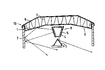
Fig. 1 a cross sechon of a radiant heat heater and
Fig. 2 distribution cur~res of the radiarlt hea~ of two vanants of this radiaIlt heat
heater. - -

CA 02252608 1998-10-20
The radia~t heat heater 10 ill~ A in figure I fec~u.~s a ~ ~g 9 in which a radiant tube
8 that ~en~ perp~n~ic~ r to the pl~e of the drawing is ~ .~ug~1 b_tw~n the lateral
borders ûf thc ho~. Above the rad~ant tube 8 ~he huuai~g 9 ha~ an upper reflector area 1
with a middle h"~ r~hl section and se~ti~ns that are laterally j~ posed laterally and are
inr1inerl down~rard toward ~he edge. The inclin~ seC~ionc are bordered at their free ends by
lateral reflector ~lern~r~tc 2 that extend downward. Abo~e ~he upper reflectûr area 1 in~ hon
rneans 7 are providet to ~U~ jJ5 heat loss, and the hsll~inE 9 is closed off at its upper side
by a hn~ n~ cover 6. A lo~rer reflector ele~Pr~t 3 is a~aDged vertically under the radiarlt
tube 8 and e~e~ti~lly has the for~ ûf an angle or triallgle in cros section, w~ch a tip pointin~
upward arld a base that is below.
The cross section of the radiant hlbe 8 features a large portion of steep ra~i~tin~ surfaces that
are additionally provided w~th a coating 5. By way of eY~rnple, fig. 1 sho~s a trape~ lly
shaped cross section ~v~th a base side that ~s on top. ~
With the radiant heat heater according to the exemplified embo~iment. the radiant heat that
}eaves the radiant tube 8 caI~ be i~fll~nced in multiple ways by reflection and/or transmission
in order to decrease the i~tensity of ~e radiant heat directed vertically downward, ~nd lhe
radiated heat r~ ting to the side at a r~di~ti-ln angle alpha (see figure 2) can be fixed in a
defined manner. The selective coating S of the radiant tube g can be used to vaIy the
sq~ sr~ loa~ ~e lateral areas of thc radian~ tube 8. ~rhe la~eral sur~aces of the radiant
tube 8 can thereby be desi~P~l to be larger rela~ive to the upper and lo~ver portions of the
r~ tin~ surfaces 4, in order to achieve ~ coLLc~ondingly greater lateral r~liptio~ The
.~.. .. .

CA 02252608 1998-10-20
_ _ _
~tli~tiQT~ ~at leaves the radiant tube 8 is ~ip~flpcted onto the lateral reflector areas 2 by the
upper reflector area 1 wi~ rela~vely flat lateral se~ ti~n~ arld iS ~ fl~e~ from ~here at an
ay~rul~;at angle into tbe space located under the h~ ng 9. A portion of ~he radia~t heat
that leaves the radia~t tube 8 in a do~~ ud direction is deflected to the side a~ the lateral
surfaces of the lowcr reflector el~Tn~nt~, into ~e space located under the housing 9.
The specifie-l measures, ~or eY~n-ple, result In a distribu~on curve b according to figure 2.
In this distribu~ion cu~e, with a ver'àcal p~ n angle alpha, the int~ty or strength of
Mrli~hon E is clearly decr~cd, while in the juxtaposed angle area at ca. 30 degrees ~e
respective m~im~ of the distribution curve ~se. If, for ~x~mrle~ the lower reflector
elern~nt 3 is removed or replaced by ano~er reAector element ~at can be ~ÇSi~nP~, e.g., as a
horizontal strip that is completely or only par~i~lly reflective and partially trausparent, the~,
e.g., the ver~ical por,tion of ~e distributiou curve is dimini~hed by less, as can be seen in ~e
distribution curve a. The vertical portion in both cases is ~limini.~hed in favor of the radiated
heat r~i.qtin~ in the lateral angular reg~on, whe~eby the degree of ef~ciency is practicAlly not
Aiminich~d at all.
As a result of the geometry and coa~ng of th~ radiant tube 8, the upper reflector area 1, ~e
lateral reflector area 2 and ~e lower reflector element 3, suitable distribution cun~es can be
generated by means of a~ ,pliate v~a:~ions, whereby a greater decrease in the radiated heat
~ ~e cent~r ~ p~icul-rly ~dv nta~cous for room heights that are low. .
The visual appearance of ~he radiant heat heater can also be varied by coating the stripsj~o
... .... ..... . .. ..

CA 02252608 1998-10-20
that it ca~ also be used, e.g. as a built in, ll~u~t~d o~ h~ radiant body in offices or
wai~ing roo~s.
.
Claims
6 .__.

Representative Drawing
A single figure which represents the drawing illustrating the invention.
Administrative Status

2024-08-01:As part of the Next Generation Patents (NGP) transition, the Canadian Patents Database (CPD) now contains a more detailed Event History, which replicates the Event Log of our new back-office solution.

Please note that "Inactive:" events refers to events no longer in use in our new back-office solution.

For a clearer understanding of the status of the application/patent presented on this page, the site Disclaimer , as well as the definitions for Patent , Event History , Maintenance Fee  and Payment History  should be consulted.

Event History

Description Date
Time Limit for Reversal Expired 2002-04-18
Application Not Reinstated by Deadline 2002-04-18
Deemed Abandoned - Failure to Respond to Maintenance Fee Notice 2001-04-18
Inactive: IPC assigned 1999-01-11
Inactive: First IPC assigned 1999-01-11
Classification Modified 1999-01-11
Inactive: IPC assigned 1999-01-11
Inactive: Notice - National entry - No RFE 1998-12-18
Application Received - PCT 1998-12-11
Application Published (Open to Public Inspection) 1997-10-30

Abandonment History

Abandonment Date Reason Reinstatement Date
2001-04-18

Maintenance Fee

The last payment was received on 2000-04-03

Note : If the full payment has not been received on or before the date indicated, a further fee may be required which may be one of the following

  • the reinstatement fee;
  • the late payment fee; or
  • additional fee to reverse deemed expiry.

Please refer to the CIPO Patent Fees web page to see all current fee amounts.

Fee History

Fee Type Anniversary Year Due Date Paid Date
Basic national fee - small 1998-10-20
MF (application, 2nd anniv.) - small 02 1999-04-19 1998-10-20
MF (application, 3rd anniv.) - small 03 2000-04-18 2000-04-03
Owners on Record

Note: Records showing the ownership history in alphabetical order.

Current Owners on Record
STEFAN KEMNA
Past Owners on Record
None
Past Owners that do not appear in the "Owners on Record" listing will appear in other documentation within the application.
Documents

To view selected files, please enter reCAPTCHA code :


To view images, click a link in the Document Description column. To download the documents, select one or more checkboxes in the first column and then click the "Download Selected in PDF format (Zip Archive)" or the "Download Selected as Single PDF" button.

List of published and non-published patent-specific documents on the CPD .

If you have any difficulty accessing content, you can call the Client Service Centre at 1-866-997-1936 or send them an e-mail at CIPO Client Service Centre.


Document
Description 
Date
(yyyy-mm-dd) 
Number of pages   Size of Image (KB) 
Description 1998-10-20 6 214
Abstract 1998-10-20 1 46
Drawings 1998-10-20 1 21
Claims 1998-10-20 3 67
Cover Page 1999-01-19 1 40
Representative drawing 1999-01-19 1 6
Notice of National Entry 1998-12-18 1 192
Courtesy - Abandonment Letter (Maintenance Fee) 2001-05-16 1 182
Reminder - Request for Examination 2001-12-19 1 117
PCT 1998-10-20 10 321