Note: Descriptions are shown in the official language in which they were submitted.
CA 022~2782 1998-10-27
W O 98/18398 PCTrUS97/19249
METHOD FOR IMPROVED SELECIIVITY IN PHOTO-ACTIVATION
AND
DETECTION OF MOLECULAR DL4.GNOSTIC AGENTS
S This invention was made with Government support under Contract No. DE-
AC05-840R21400 awarded by the U.S. Department of Energy to Lockheed Martin
Energy Systems, Inc. Lockheed Martin Energy Systems and the Oak Ridge
Associated Universities have waived rights to this invention to the inventors. The
Government has rights in this invention pursuant to Contract No. DE-AC05-
840R21400 awarded by the U.S. Department of Energy.
BACKGROUND OF THE INVENTION:
Field of the Invention:
The present invention relates generally to methods and apparatus for remotely
effecting spatially-selective photo-activation of one or more molecular agents and for
il.lpruving the detection of the diagnostic signals thereby produced. The methodtaught for effecting photo-activation utilizes the special properties of non-linear
optical excitation for promoting an agent from one molecular energy level to another
with a high degree of spatial and molecular specificity. The special features of this
method are applicable for activation of various endogenous and exogenous imagingagents, and in particular afford distinct advantages in the diagnosis of diseases in
humans and ~nim~l.c. Specifically, use of non-linear excitation methods facilitate
controlled activation of diagnostic agents in deep tissue using near infrared toinfrared radiation, which is absorbed and scattered to a lesser extent than methods
and radiations currently used. Combination of these non-linear excitation methods
- with advanced signal encoding and processing methods greatly increases sensitivity
in the detection of diagnostic signals.
Description of the Prior Art:
An urgent need exists in many fields, and especially in the medical diagnostics
field, for a method that is capable of selectively controlling the remote activation of
various molecular agents while producing few if any side effects resulting from the
activation process. The desired hlll)luv~nlents in activation indude enhancements in
CA 022~2782 1998-10-27
WO 98/18398 PCT/US97119249
spatial or temporal control over the location and depth of activation, reduction in
undesirable activation of other co-located or proximal molecular agents or structures,
and increased preference in the activation of desirable molecular agents over that of
undesirable molecular agents. Various linear and non-linear optical methods havebeen developed to provide some such improvements for some such agents under veryspecialized conditions. However, in general the performance and applicability ofthese methods have been less than desired. Specifically, improved photo-activation
methods are needed that may be used to selectively photo-activate a variety of
molecular diagnostic agents while providing illlpl~ved performance in the control of
application of this photo-activation.
Application of optical radiation as a means for remotely activating molecular
probes has been known for many years. Specifically, linear optical excitation methods
have been used extensively as a means for achieving semi-selective activation ofmolecular diagnostic agents. Linear optical excitation occurs when a target agent,
such as a molecular diagnostic agent, undergoes a specific photo-chemical or photo-
physical process, such as fluorescent emission, upon absorption of energy provided
by a single photon. These processes can in many cases be very efficient, and use of
such processes is attractive for numerous applications. Unfortunately, performance
of these linear methods have not always been as successful as desired. For example,
there is strong evidence that ultraviolet radiation used to excite some molecular
probes can produce disease in humans and animals, such as induced skin cancer,
along with other undesirable side effects. Furthermore, a less than desirable
penetration depth has plagued most efforts at linear optical excitation of molecular
agents, primarily as a conse~uence of the effects of optical scatter and of absorbance
of the incident probe radiation at wavelengths near the linear absorption bands of
these agents. As an example,-Wachter and Fisher (E.A. Wachter and W.G. Fisher,
"Method and Apparatus for Evaluating Structural Weakness in Polymer Matrix
Composites," U.S. Patent 5,483,338) teach of a rapid optical method capable of
sensitively im~ging chemical transformations in probe molecular agents; however,due to scatter and absorbance of the incident probe radiation, the method is only
suitable for topical analysis. Vo-Dinh and co-workers (T. Vo-Dinh, M. Panjehpour,
B.F. Overholt, C. Farris, F.P. Buckley III and R. Sneed, "In-Vivo Cancer-Diagnosis
CA 022~2782 1998-10-27
W O 98118398 PCT~US97tl9249
of the Esophagus Using Differential Norm~1i7e~1 Fluorescence (Dnf) Indexes," Lasers
in Surgery and Medicine, 16 (1995) 41-47; and M. Panjehpour, B.F. Overholt, J.L.Schmi-lh~mmer, C. Farris, P.F. Buckley, and T. Vo-Dinh, "Specl~oscopic Diagnosisof Esophageal Cancer: New Classification Model, Improved Measurel.lent System,"
Gastrointestinal Endoscopy, 41 (1995) 577-581) teach of the use of similar linear
optical probe methods for detection of diseased tissues in humans; however, thisapproach is also plagued by less than desirable penetration depth and is limited to
detection of superficial lesions due to scatter and absorption of the incident probe
radiation. Also, because this type of excitation is linearly related to excitation power,
such methods provide no ef~ective means for limiting the location of probe excitation
along the optical path. In fact, virtually all examples of the use of linear optical
excitation are plagued by fundamental performance limits that are attributable to
undesirable absorption and scatter of the incident optical radiation by the
~u~lounding matrix, poor specificity in excitation of probe molecular species, and a
lack of suitable physical mech~ni~m~ for precise control of the extent and depth of
activation.
Various non-linear optical excitation methods have been employed in an effort
to achieve specific improvements in the selectivity of photo-activation for certain
applications, and to address many of the limitations posed by linear excitation
methods. In fact, the non-linear process con~i~ting of simultaneous absorption of two
photons of light by a molecule to effect excitation equivalent to that resulting from
absorption of a single photon having twice the energy of these two photons is very
well known, as are the specific advantages of this process in terms of reduced
absorption and scatter of excitation photons by the matrix, enhanced spatial control
over the region of excitation, and reduced potential for photo-chemical and photo-
physical damage to the sample. Excitation sources ranging from single-mode,
co~ uous wave (CW) lasers to pulsed Q-switched lasers having peak powers in
excess of 1 GW have been employed for numerous examples of two-photon excitationmethods. For e~ )lc, Wirth and Lytle (M.J. Wirth and F.E. Lytle, "Two-Photon
Excited Molecular Fluorescence in Optically Dense Media," Analytical Chemistry, 49
(1977) 2054-2057) teach use of non-linear optical excitation as a means for
stimulating target molecules present in optically dense media; this method is shown
CA 022~2782 1998-10-27
W O 98/18398 PCT~US97il9249
to be useful in limiting undesirable direet interaetion of the probe radiation with the
media itself, and provides a means for effeetively exciting target moleeular agents
present in strongly absorbing or seattering matriees. Im~ ved spatial eontrol over
the aetive region has been further developed by Wirth (M.J. Wirth and H.O.
Fatunmbi, "Very High Deteetability in Two-Photon Spectroscopy," Analytical
Chemistry, 62 (1990) 973-976); specifically, Wirth teaches a method for achieving
extremely high spatial selectivity in the exeitation of target moleeular agents using a
mlcroseoplc lm~glng system.
Similar control has been further applied by Denk et al. (W. Denk, J.P.
Strickler and W.W. Webb, "Two-Photon Laser Microscopy," U.S. Patent No.
5,034,613) who teach of a special epi-ilhlmin~tion confoeal laser sc~nning mieroscope
utilizing non-linear laser excitation to achieve intrinsieally high three-dimensional
control in the photo-activation of various molecular fluorophor agents on a eellular
or sub-cellular scale. Denk, however, is specifically direeted to microscopy, wherein
a microscope is used to look at samples on a slide. This microscope is used to excite
molecular fluorophor agents added to biological speeimens, which constitute an
optically dense medium. In Denk, light from a laser travels downward as a result of
being reflected by a mirror onto an object plane. Fluorescent light then travels back
along that same optical path, through an objeetive lens, a series of ~ and
ultimately a photomultiplier tube. Henee, light is merely focussed on the objeet plane
of a slide and refleeted back. The special properties of non-linear two-photon
excitation are utilized to substantially limit excitation and subsequent detection of the
fluorescent signal thus produced to a confocal region oceurring at the focus of an
objective lens, thereby enhancing contrast in three-dimensional im~ging by sharply
controlling the depth of foeus. -Emitted fluoreseent light is collected by the exeitation
objective using an epi-illumination configuration. Control of photo-excitation for
generation of luminescence-based images at the cellular and sub-cellular level is
shown in target samFles mounted on a stage. Furthermore, Denk teaches that
reduction in photo-induced necrosis of cells located at the focal plane is a primary
benefit of this microscopy approach, based on the replaeement of ultraviolet
excitation radiation with less damaging near infrared excitation radiation.
CA 022~2782 1998-10-27
W O 98/18398 PCT~US97/19249
In later work by Denk et al. (W. Denk, D.W. Piston and W.W. Webb, "Two-
Photon Molecular Exeitation in Laser-Sc~nning Mieroscopy," in Handbook of
Biological Confocal Mic-osco~y, Second Edition, J.B. Pawley, ed., Plenum Press, New
York, 1995, pp. 445-458) an external whole area detection method is taught for
S collection of mieroseopie imaging data produced from two-photon excited ~luorescent
tags. This method, which the authors state as being "as yet untried," eliminates the
need to eollect b~clrcc~ttered fluoreseent light using epi~ min~tion (see p. 452).
Denk points out that this approach could be useful if the mieroseope objective does
not transmit the emitted fluoreseent wavelengths, but that it is "vulnerable to
contamination from ambient room light." In this work and in the earlier Denk patent
(5,034,613), no apparent method is used or anticipated for reduction of bach~loulld
interferenee from either ambient light or from scattered excitation light.
In fact, the well known low efficiency of the two-photon excitation process can
translate into a very high ratio of scattered, unabsorbed excitation light to
fluorescence emission. Use of various modulation methods for reduction of
interference from scattered excitation light, as well as from interferences fromambient light and from other environmental and instrumental bac~glound sources,
has numerous precedents. In the field of two-photon excited fluorescence, Lytle and
co-workers (R.G. Freeman, D.L. Gilliland and F.E. Lytle, "Second Harmonic
Detection of Sinusoidally Modulated Two-Photon Excited Fluorescence," AnalyticalChemistry, 62 (1990) 2216-2219; and W.G. Fisher and F.E. Lytle, "Seeond HarmonieDetection of Spatially Filtered Two-Photon Excited Fluorescence," Analytical
Chemistry, 65 (1993) 631-635) teach sophisticated methods for rejection of scattered
laser excitation light by m~king use of second-harrnonic detection methods- whensinusoidal modulation of the excitation light is performed at one frequency, anddeteetion of the two-photon excited fluorescence is performed at twice that frequency
(whieh is the second harmonic of the exeitation modulation frequency), interferences
- from scattered excitation light are virtually elimin~ted. And by proper selection of
the modulation frequency to avoid electronic and other noise frequencies, rejection
of instrumental and ellvilonmental interferences is extremely high.
CA 022~2782 1998-10-27
W O 98/18398 PCTrUS97119249
Hence, it is well known that two-photon excitation of fluorescence can be used
under laboratory conditions to excite molecular fluorophors using light at
applo~i...7.tely twice the wavelength of that used for linear single-photon excitation,
and that the excitation thereby effected can iL~Iplove three-dimensional spatial control
over the location of excitation, can reduce interference from absorption and scatter
of the excitation light in optically dense media, and can reduce collateral damage
along the excitation path to living cell samples undergoing microscopic e~min~tion.
Nonetheless, while the substantial body of prior art exemplified by these cited
examples clearly demonstrates many attractive features of various photo-activation
methods that are applicable for diagnostic and other in vivo microscopic im~ginguses, a general method for achieving selective photo-activation of one or more
molecular agents with a high degree of spatial control that is capable of meeting the
diverse needs of the medical diagnostic industry has not been previously taught.Specifically, practical methods for effecting such control on scales that are significant
for medical diagnostic applications have not been previously taught.
It is, therefore, an object of the present invention to provide a general methodfor achieving selective photo-activation of one or more molecular agents with a high
degree of spatial control.
It is another object of the present invention to provide such a method that is
capable of meeting the diverse needs of the medical diagnostic industry.
It is another object of the present invention to provide a practical method for
effecting such control on scales that are significant for medical diagnostic
applications.
SUMMARY OF THE INVENTION:
Having regard to the above and other objects and advantages, the present
invention generally provides for a method for the imaging of a particular volume of
plant or animal tissue, wherein the plant or animal tissue contains at least one photo-
active molecular agent. The method complises the steps of treating the particular
volume of the plant or animal tissue with light sufficient to promote a simultaneous
two-photon excitation of the photo-active molecular agent contained in the particular
volume of the plant or animal tissue, photo-activating at least one of the at least one
CA 022~2782 1998-10-27
W O 98/18398 PCTAJS97/19249
photo-active molecular agent in the particular volume of the plant or animal tissue,
thereby producing at least one photo-activate~ molecular agent, wherein the at least
one photo-activated molecular agent emits energy, detecting the energy emitted by
the at least one photo-activated molecular agent, and producing a detected energy
signal which is characteristic of the particular volume of plant or animal tissue. The
present invention also provides a method for the im~ging of a particular volume of
material, wherein the material contains at least one photo-active molecular agent.
In a preferred embodiment of the present invention, the light sufficient to
promote a simultaneous two-photon excitation of the at least one photo-active
molecular agent is laser light. It is also preferred that the light sufficient to promote
a simultaneous two-photon excitation of the photo-active molecular agent is a focused
beam of light, and more preferred that the focused beam of light is focused laser
light.
Another preferred embodiment of tbe present invention further includes a first
step of treating the material, plant tissue or animal tissue with at least one photo-
active molecular agent, wherein the particular volume of the material, plant tissue or
animal tissue retains at least a portion of the at least one photo-active molecular
agent. It is more preferred that the at least one photo-active molecular agent is
selected from the group concicting of psora1en, 5-methoxypsoralen (5-MOP), 8-
methoxypsoralen (8-MOP), 4,5',8-trimethylpsoralen (TMP), 4'-aminomethyl-4,5',8-
trimethylpsoralen (AMT), S-chloromethyl-8-methoxypsoralen (HMT), angelicin
(isopsoralen), 5-methylangelicin (S-MIP), 3-carboxypsoralen, porphyrin,
haematoporphyrin derivative (HPD), photofrin II, benzopolyLy~ derivative (BPD),
protoporphyrin IX (PpIX), dye haematoporphyrin ether (DHE),
polyhaematoporphyrin esters (PHE), 13,17-N,N,N-dimethylethylethanolamine ester
of protoporphyrin (PH1008), tetra(3-hydroxyphenyl~-porphyrin (3-THPP),
tetraphenylporphyrin monosulfonate (TPPS1), tetraphenylporphyrin disulfonate
(TPPS2a), dihaematoporphyrin ether, mesotetraphenylporphyrin, mesotetra(4N-
methylpyridyl)porphyrin (T4MpyP), octa-(4-tert-butylphenyl)tetrapyrazinopoJI.hy~ e
(OPTP), phthalocyanine, tetra-(4-tert-butyl)phthalocyanine (t4-PcH2), tetra-(4-tert-
butyl)phthalocyanatomagnesium (t4-PcMg), chloroaluminum sulfonated
phthalocyanine (CASPc), chloroaluminum phthalocyanine tetrasulfate (AlPcTS),
CA 022~2782 1998-10-27
W O 98/18398 PCTrUS97/19249
mono-sulfonated aluminum phthalocyanine (AlSPc), di-sulfonated alumillu,-l
phthalocyanine (AlS2Pc), tri-sulfonated aluminum phthalocyanine (AlS3Pc), tetra-sulfonated alull~ ulll phthalocyanine (AlS4Pc), silicon phthalocyanine (SiPc IV), zinc
II phthalocyanine (ZnPc), bis(di-isobutyl octadecylsiloxy)silicon 2,3-naphthalocyanine
(isoBOSINC), germanium IV octabul~Ay~hthalo-cyanine (GePc), rhodamine 101 (Rh-
101), rhodamine 110 (Rh-110), rhodamine 123 (Rh-123), rhodamine 19 (Rh-19),
rhodamine 560 (Rh-560), rhodamine 575 (Rh-575), rhodamine 590 (Rh-590),
rhodamine 610 (Rh-610), rhodamine 640 (Rh-640), rhodamine 6G (Rh-6G),
rhodamine 700 (Rh-700), rhodamine 800 (Rh-800), rhodamine B (Rh-B),
sulforhodamine 101, sulfo-rhodamine 640, sulforhodamine B, coumarin 1, coumarin
2, coumarin 4, coumarin 6, coumarin 6H, coumarin 7, coumarin 30, coumarin 47,
coumarin 102, coumarin 106, coumarin 120, coumarin 151, coumarin 152, coumarin
152A, coumarin 153, coumarin 311, coumarin 307, coumarin 314, coumarin 334,
coumarin 337, coumarin 343, coumarin 440, coumarin 450, coumarin 456, coumarin
460, coumarin 461, coumarin 466, coumarin 478, coumarin 480, coumarin 481,
coumarin 485, coumarin 490, coumarin 500, coumarin 503, coumarin 504, coumarin
510, coumarin 515, coumarin 519, coumarin 521, coumarin 522, coumarin 523,
coumarin 535, coumarin 540, coumarin 540A, coumarin 548, 5-ethylamino-9-
diethylamino-benzo[a]phenoxazinium (EtNBA), 5-ethyl-amino-9-diethyl-
aminobenzo[a]phenot~ iniu~EtNBS)~-ethylamino-9-diethylaminobenzo[a]pheno-
selenazil,ium (EtNBSe), chlol~rol-lazine, chlorpromazine delivalives, chlorophyll
derivatives, bacteriochlorophyll derivatives, metal-ligand complexes, tris(2,2'-bipyridine)ruthenium (II) dichloride (RuBPY), tris(2,2'-bipyridine)rhodium (II)
dichloride (RhBPY), tris(2,2'-bipyridine)platinum (II) dichloride (PtBPY),
pheophorbide a, merocyanine 540, vitamin D, 5-amino-laevulinic acid, photosan,
chlorin e6, chlorin e6 ethylene-diamide, mono-L-aspartyl chlorin e6, and phenoxazine
Nile blue delivalives, stilbene, stilbene derivatives, and 4-(N-(2-hydloAyethyl)-N-
methyl)-aminophenyl)-4'-(6-hydroxyhexylsulfonyl)-stilbene (APSS). It is also more
preferred that the at least one photo-active molecular agent is at least one biogenic
photo-active molecular agent that is specific to a particular material or tissue within
the particular volume of material, plant tissue or animal tissue, even more preferred
that the at least one biogenic photo-active molecular agent includes a segment
CA 022~2782 1998-10-27
W O 98/18398 PCT~US97119249
selected from the group consisting of DNA, RNA, amino acids, proteins, antibodies,
ligands, haptens, carbohydrate receptors or complexing agents, lipid receptors or
complexing agents, protein receptors or complexing agents, chelators, and
- encapsulating vehicles and yet further more preferred that the at least one biogenic
photo-active molecular agent further includes a segment which is photo-activatedwhen subject to light sufficient to promote a simultaneous two-photon excitation.
In yet another preferred embodiment of the present invention, the step of
treating the particular volume of the material, plant tissue or animal tissue with light
sufficient to promote a simultaneous two-photon excitation of the at least one photo-
active molecular agent contained in the particular volume of the material, plant tissue
or animal tissue further includes the step of modulating light from a light source with
a particular type of modulation, thereby producing a modulated light, and the step
of treating the particular volume of the material, plant tissue or animal tissue with
the modulated light sufficient to promote a simultaneous two-photon excitation of the
at least one photo-active molecular agent contained in the particular volume of the
material, plant tissue or animal tissue. It is also preferred that the present invention
further include the steps of demodulating the dectected energy signal with the
particular type of modulation, and producing a demodulated energy signal which is
characteristic of the particular volume of the material, plant tissue or animal tissue.
It is more preferred that the step of demodulating the dectected energy signal
with the particular type of modulation includes demodulating the detected energysignal at a frequency twice that of the particular type of modulation, thereby
detecting the second harmonic of the particular type of modulation. It is also more
preferred that the demodulated energy signal which is characteristic of the particular
volume of the material, plant tissue or animal tissue represents a change in lifetime
of at least one photo-activated molecular agent present in the particular volume of
the material, plant tissue or animal tissue.
BRIEF DESCRIPTION OF THE DRAWINGS:
The above and other features and advantages of the invention will become
further known from the following detailed description of preferred embodiments of
the invention in conjunction with the drawings in which:
CA 022~2782 1998-10-27
W O 98/18398 PCT~US97119249
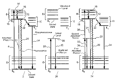
FIGURE 1 shows example energy level diagrams for linear and non-linear
optical excitation;
FIGURE 2 shows the relationships between incident power distribution and
excitation efficiency for single-photon and two-photon excitation;
5FIGURE 3 shows an example absorption spectrum for animal tissue covering
the ultraviolet to near infrared spectral region;
FIGURE 4 shows a scattering spectrum for animal tissue covering the
ultraviolet to near infrared spectral region;
FIGURE 5 shows the general trends in optical absorption and scattering
10properties of tissue for incident short wavelength and long wavelength light;
FIGURE 6 compares optically-induced excitation regions in tissue when single-
photon and two-photon excitation methods are used;
FIGURE 7 shows typical properties of linear excitation of a diagnostic agent
in solution;
15FIGURE 8 shows typical properties of non-linear excitation of a diagnostic
agent in solution;
FIGURE 9 shows a photograph of two-photon excited fluorescence of the dye
molecule coumarin 480 distributed evenly throughout a tissue phantom;
FIGURE 10 shows a photograph of two-photon excited fluorescence of the
20dye molecule coumarin 480 distributed evenly throughout a tumor specimen;
FIGURE 11 shows a diagram of a specific preferred embodiment of the
subject invention for im~ging endogenous or exogenous diagnostic imaging agents;FIGURE 12 shows a diagram of an alternate preferred embodiment of the
subject invention for im~ging endogenous or exogenous diagnostic im~ging agents,25wherein modulation is used to improve im~ging performance; and
FIGURE 13 shows a diagram of a second alternate preferred embodiment of
the subject invention for videographic imaging of superficial features.
DETAILED DESCRIPTION OF THE DRAWINGS:
30The invention described here utilizes the unique physical properties of non-
linear optical excitation of molecular agents to effect inlpr~ved spatial control over
the photo-activation of those agents. In addition, non-linear optical excitation is
CA 022~2782 1998-10-27
W O 98/18398 PCTrUS97/19249
shown to have further advantages during photo-activation of medical diagnostic and
other agents, including reduction of collateral excitation and damage along the
excitation path, reduction in exposure to harmful optical wavelengths, and reduction
of interference from absorption and scattering processes originating from the
S environmeDt ~,ulloullding the excited agent.
The fundamental significance of the invention taught in this disclosure lies in
the use of non-linear, simultaneous two-photon optical excitation processes to
remotely photo-activate one or more molecular diagnostic agent with a high degree
of spatial control and improved depth of penetration. These molecular agents maybe exogenous agents added to the system under examination, or they may be
endogenous components of the system. Example exogenous diagnostic agents includevarious psoralen derivatives, while example endogenous agents include aromatic
amino acids and nucleic acids. Two-photon excitation is performed at a wavelength
apprnxim~tely twice that of corresponding single-photon absorbance bands. By
focussing a beam of optical radiation into a specimen under e~r~min~tion~ the
diagnostic agent may be excited at a location substantially limited to the confocal
region of the focussed beam. The confocal region, Zc, is defined as the zone
extending a distance of 27r wo2 / ~, where wO is the diameter of the ~ hllulll beam
waist and ~ is the wavelength of the optical radiation. In contrast, when linearexcitation methods are employed, excitation occurs substantially along the entire
optical path, m~king spatial localization of excitation considerably less defined. Thus,
use of the two-photon excitation process greatly increases the resolution of excitation
along the optical path. Further, since excitation is performed at long wavelengths
relative to corresponding linear excitation processes, scatter and absorption of the
excitation energy is greatly reduced. For thick, optically dense samples, such as
human tissue, this means that two-photon excitation is possible at depths considerably
greater than is possible using linear excitation methods. It is not necessary for the
light emitted from the diagnostic agent to be detected or imaged directly without
scatter, since spatial information concerning the origin of the emitted light is encoded
by and may be correlated to the excitation focus. By moving the location of thisfocus relative to the specimen, a two- or three-dimensional image of the emitted light
may be developed. Also, by modulating the excitation light and using an appro~uliate
,
CA 022~2782 1998-10-27
W O 98/18398 PCTrUS97/19249
demodulation method on the detection apparatus, rejection of scattered excitation
light and other interferences may be markedly hl,pr~ved.
The present invention is intended primarily for in vivo detection and imaging
of disease and other characteristics of tissues, such as cancer in the human breast.
However, it will be clear once the invention is fully disclosed that the methods and
apparatus taught have numerous additional applications, and that these methods and
apparatus can be applied to the field of two-photon laser sc~nning microscopy, as
taught by Denk et al., to achieve substantive improvements in the perforrnance
characteristics of such instruments. To begin this full disclosure, a review of the
fundamental physics underlying linear and non-linear optical excitation will be useful.
Comparison of linear and non-linear excitation - energy level dia~ram forrnulation:
FIGURE 1 shows typical molecular energy level diagrams for several linear
and non-linear optical excitation processes. In this representation, which consists of
simplified Jablonski diagrams, the vertical direction corresponds to a change inenergy, while the horizontal direction represents the sequence of events, progressing
from the left to right. Solid horizontal lines represent quantum mechanically allowed
molecular energy levels, while dashed horizontal lines represent disallowed, virtual
energy levels. Quantum mechanically allowed molecular energy levels are relatively
long lived and the probability of excitation of a molecule upon absorption of energy,
such as that provided by absorption of a photon of app~ iate energy, is high.
Virtual energy levels may be reached through a variety of excitation processes, but
in contrast to allowed molecular transitions they have e~(~ee-lingly short lifetimes (on
the order of 10-15 s, as predicted by the Heisenberg uncertainty principle), making
them significant only under special excitation conditions. Straight arrows in Jablonski
diagrams represent radiative energy transfer processes: upward arrows indicate
absorption of energy, while downward arrows represent radiative emission, such as
i~uorescent or phosphorescent emission of a photon. Crooked arrows represent non-
radiative energy transfer processes, such as vibrational relaxation. The vertical
length of the straight or crooked arrows is proportional to energy absorbed or
emitted in a given process.
CA 022~2782 1998-10-27
W O 98/18398 PCT~US97/19249
For the first Jablonski diagram shown in FIGURE 1, single-photon excitation
to an allowed energy level 2 occurs upon absorption of a photon 4 having sufficient
energy to directly promote the molecule from a first allowed electronic energy level
6 (generally the lowest electronic energy level, or ground state, denoted as S0) to a
S second allowed electronic energy level 8 having a higher overall energy level
(represented here as the Sl state). Note that there may be multiple allowed higher
electronic energy levels to which excitation may occur, and that these are typically
denoted Sl, S2, and so on as their energy increases. The nomenclature Sl indicates
a singlet electronic energy level that conforms to the Pauli exclusion principle,
wherein the spins of all electrons are paired and these paired electron spins are
opposite to one another. One or more triplet excited states 10 may also be possible
for some molecular systems, with the example here denoted as T1. Triplet states
differ from singlet states in that the spins of all electrons are paired except for two.
Each allowed electronic energy level (singlet or triplet) may be further subdivided
into an ensemble of discrete vibrational levels 12; each of these discrete vibrational
levels 12 may in turn be further subdivided into an ensemble of discrete rotational
energy levels. Hence, each allowed electronic energy level, S0, S1, Tl, and so on,
constitutes a complex band of allowed energy levels due to the large number of
possible vibrational and rotational states possible. Upon absorption of energy from
a photon 4 the molecule is promoted to a particular unique electronic and vibrational
level 14, sometimes referred to as a vibronic level. From this excited state themolecule can then undergo rapid internal conversion 16, for example to the lowest
allowed excited vibronic energy level 18 in the second allowed electronic energy level
8. This internal conversion 16 is typically very fast, occurring on a time scale on the
order of 10-l2 to 10-15 sec. Finally, the excited molecule can undergo fur.her
relaxation, such as through collisional deactivation 20, to return to the initial, first
energy level 6. Alternative relaxation processes include fluorescent emission of a
photon 21, which occurs directly from S1 to S0, and phosphorescence, which occurfollowing intersystem crossing 22 from a singlet state to a triplet state 10. Note that
singlet to singlet electronic transitions, such as those shown for S1 ~ S0, constitute
quantum mechanically allowed transitions accordil-g to the Pauli exclusion principle.
In contrast, transitions from a singlet to a triplet state 10, such as Sl ~ T1, are
CA 022~2782 1998-10-27
WO 98/18398 PCTrUS97119249
14
quantum mechanically forbidden since the electron spins do not remain paired.
However, the probability of internal conversion is greater than zero for some
molecular systems as a consequence of the relatively long lifetime of the Sl state
compared to the intersystem crossing rate constant for these systems. Transitionfrom the triplet state 10 back to a singlet state, such as Tl ~ S0, can occur via the
radiative process known as phosphorescent emission of a photon 24.
Phosphorescence is generally characterized by a relatively long radiative lifetime
compared to iluorescence due to the disallowed nature of the process. An exampleof single-photon excitation to an allowed energy level 2 is promotion of the dyemolecule coumarin from a ground e}ectronic state to an excited electronic state
through the absorption of a single photon 4 at 400 nm, followed by internal
conversion 16 and subsequent fluorescent emission of a photon 21 at 480 nm. In this
example the probability of excitation is linearly related to the power of the incident
optical radiation, thus single-photon excitation to an allowed energy level 2 is referred
to as a linear excitation process.
For the second Jablonski diagram shown in FIGURE 1, single-photon
excitation to a virtual energy level 26 occurs upon absorption of a photon 28 having
insufficient energy to directly promote the molecule to a higher allowed electronic
energy level 8. Instead, the molecule is promoted to a very short lived virtual energy
level 30. This virtual energy level 30 will typically have a lifetime on the order of 10-
15 sec. Virtually instantaneous re-emission 32 of the absorbed photon 28 from this
virtual level 30 will typically occur via processes such as elastic scatter. An important
example of this process is Rayleigh scatter at 800 nm from coumarin upon excitation
with light at 800 nm. Another example is Raman scatter, which occurs when the
molecule returns to the various vibrational levels associated with the ground state.
In these example processes the probability of excitation is also linearly related to the
power of the incident optical radiation, thus single-photon excitation to a virtual
energy level 26 is also referred to as a linear excitation process.
For the final Jablonski diagram shown in FIGURE 1, simultaneous two-photon
3~ excitation to an allowed energy level 34 occurs upon simultaneous absorption of a
first of two photons 36 and a second of two photons 38. In this case the combined
energy of the first of two photons 36 and the second of two photons 38 is sufficient
CA 022~2782 1998-10-27
W O 98/18398 PCT~US97/19249
to promote the molecule from a first allowed energy level 6 to a second allowed
energy level 8. Typically, the individual energies of neither the first of two photons
36 nor the second of two photons 38 is sufficient to directly promote this or any other
allowed electronic transition. Instead, the first of two photons 36 promotes theS molecule to a very short lived virtual energy level 30. This is the same virtual energy
level as that shown in the second Jablonski diagram. Before re-emission 32 can occur
from the virtual energy level 30, the second of two photons 38 immediately promotes
the molecule to a second allowed electronic energy level 8. The result is excitation
that is equivalent to that achieved using linear single-photon excitation to an allowed
energy level 2. Note that the first of two photons 36 and the second of two photons
38 may be of equal or unequal energy. Also, the instantaneous irradiance, or W m~2,
of the incident excitation light must be relatively high to yield significant efflciency
in absorption of the second of two photons 38 before the virtual energy level 30undergoes relaxation 32 back to the original first allowed electronic energy level 6.
In fact, because the lifetime of the virtual energy level 30 is on the order of 10-15 sec,
pulsed excitation sources having very high peak powers are commonly used to
efficiently stimulate these processes; such sources are often preferable since they are
capable of providing large numbers of photons to the excited molecule during thebrief lifetime of the virtual energy level 30. Once the molecule has been promoted
to the second allowed electronic energy level 8, it can then undergo rapid internal
conversion 16, followed by further relaxation, such as through collisional deactivation
20, iluorescent emission of a photon 21, or intersystem crossing 22 to a triplet state
10. In the last case, transition from the triplet state 10 back to the singlet ground
state 6, can occur via phosphorescent emission of a photon 24. It is notable that
simultaneous two-photon excitation shares features of both single-photon excitation
to an allowed energy level 2 and single-photon excitation to a virtual energy level 26,
specifically in that a virtual energy level 30 plays a key role in the promotion of the
molecule from the ground state to the excited state, and that once promoted to an
excited energy level the molecule can undergo photo-chemical and photo-physical
processes that are identical to those resulting from single-photon excitation to an
allowed energy level 2. An example of the simultaneous two-photon excitation
process is the promotion of the dye molecule coumarin from a ground electronic state
CA 022~2782 l998-l0-27
W O 98/18398 PCT~US97/19249
16
to an excited electronic state through the simultaneous absorption of two photons at
800 nm, followed by emission of a fluorescent photon at 480 nm. Due to the well
known quadratic dependence on instantaneous photon irradiance, simultaneous two-photon excitation to an allowed energy level 50 is also referred to as a non-linear
excitation process. The significant differences between linear and non-linear
excitation processes are identified in the next section.
Note that in addition to the example energy level diagrams shown in FIGURE
1, many other possible transitions and energy level conditions are possible, depending
upon numerous factors, including the characteristics of the molecular system, its
ellvi,~ ent, and the particular energies of the absorbed and released forms of
energy, along with their temporal and spatial correlations. Once a molecule has been
- promoted to an excited state, a variety of physical or chemical processes may occur,
including luminescent emission of a photon, photochemical transformation, such as
isomerization or oxidation, or photo-ionization. Il.lpolL~lltly, though, it is the
fundamental properties of the excited state and its ellviron"lent that determine the
ultimate fate of the molecule. Once excited, the meGh~ni~m responsible for
promoting the molecule to the excited state has no significant impact on this fate
since the excitation process itself does not directly impact the subsequent properties
of the excited molecule or its envilo~ ent. Hence, a molecular diagnostic agent that
works well under single-photon excitation conditions may be expected to exhibit
similar behavior under two-photon excitation conditions.
Comparison of linear and non-linear excitation - power dependence and spatial
effects:
When light interacts wvith a molecular system, it induces a polarization that isproportional to the linear susceptibility multiplied by the magnitude of the applied
electric field. When this electric field is very intense, the system cannot be described
as easily, and higher order interaction terms must be included in the descliplion of
the induced polarization. Simultaneous two-photon excitation is referred to as a non-
linear process because it occurs when the electromagnetic fields from two photons
combine via these higher order terms, specifically the im~gin~ry portion of the third-
order susceptibility, %(3), to induce an electronic transition. This is another way of
CA 022~2782 1998-10-27
W O 98/18398 PCTAJS97/19249
describing the non-linearity of simultaneous two-photon absorption. That is, themolecular system is reacting non-linearly to the intense electromagnetic field. In
contrast, single-photon excitation processes may be described by the linear
susceptibility and are linear with excitation power. Note that the cross-section for
S simultaneous two-photon excitation is typically about one hundred thousand-fold
smaller than that for an equivalent single-photon excitation process. This is due to
the low probability that two photons will simultaneously interact with a molecule
during the lifetime of the extremely brief virtual energy level. However, the
availability of optical excitation sources capable of providing extremely high peak
powers, such as mode-locked lasers, can substantially ameliorate the impact of this
low efflciency by increasing instantaneous incident powers and thereby dramatically
increasing the efficiency of simultaneous two-photon excitation. For example, when
using continuous wave excitation the efficiency of two-photon excitation for a
particular molecular system may be 105 smaller than that achieved with single-photon
excitation. However, if the same average optical power is emitted in the form of a
train of very short pulses, the shift in product of the peak and average powers can
change this ratio such that it is close to uni~.
The non-linear nature of simultaneous two-photon excitation can be exploited
to achieve an important difference in the spatial excitation properties of simultaneous
two-photon excitation compared to linear excitation. For example, FIGURE 2 showsthat the single-photon excitation efficiency profile 40 and the simultaneous two-
photon excitation efficiency profile 42 differ dramatically as a function of the beam
intensity profile 44 when a laser beam 46 iS focused 48 into a material 50. Thismaterial 50 might be a laser dye solution held between the walls of a cuvette 52.
Another example of this material 50 might be human tissue underneath skin.
Focussing 48 of the laser beam 46 with a lens 54 produces a beam intensity profile
44 that varies as a function of distance through the sample 50, reaching a m~ umlevel at the center of the focus 56 as predicted by classical G~llc~i~n optical theory.
For a single-photon process, the linear relationship between beam intensity (or
incident power) and excitation efficiency results in a single-photon excitation
efficiency profile 40 that linearly follows the beam intensity profile 44. In conlld~l,
for the simultaneous two-photon process, the non-linear relationship between beam
. . .
CA 022~2782 1998-10-27
W O 98/18398 PCTrUS97/19249
18
intensity (or incident power) and excitation efflciency results in a simultaneous two-
photon excitation efflciency profile 42 that follows the square of the beam intensity
profile 44. Hence, focussing 48 the laser beam 46 can be used to substantially limit
the extent of excitation to a small focus zone, or confocal region, when simultaneous
two-photon excitation is employed. In contrast, when linear excitation is employed,
excitation occurs substantially along the entire optical path, making spatial
loc~li7~tion of excitation considerably less defined.
Comparison of linear and non-linear excitation - absorption and scattering effects:
While the cross-section for simultaneous two-photon excitation may be
considerably lower than that observed with single-photon excitation, use of
simultaneous two-photon excitation may be favorable to single-photon excitation
under many conditions because of lower matrix absorption and optical scattering of
longer wavelength optical radiation. For example, FIGURE 3 shows an absorption
spectrum 58 for animal tissue, such as human dermis or liver, covering the ultraviolet
(W) to near infrared (NIR) spectral region. FIGURE 4 shows a scattering
spectrum 66 for animal tissue, such as human dermis or liver, under similar
conditions. Specifically, FIGURE 3 demonstrates how higher-energy photons 60,
such as those used for linear excitation of diagnostic agents, may experience
considerably greater tissue absorption than lower-energy photons 62, such as those
used for non-linear excitation of diagnostic agents. For instance, human skin strongly
absorbs higher-energy photons 60 at 400 nm, but is relatively transparent to lower-
energy photons 62 at 800 nm. This is a consequence of the relatively high natural
absorbance of higher-energy photons 60, having ultraviolet or visible wavelengths, by
pigments, proteins, and genetic materials, among other natural co,l".ol,ents, of skin.
Note also the relationship between excitation energies and the emission wavelength
64 of the diagnostic agent. Regardless of whether higher-energy photons 60 or lower-
energy photons 62 are used to excite the agent, the emission wavelength 64 will occur
at an energy that is determined by the agent, not the excitation method applied to
the agent. FIGURE 4 further demonstrates how higher-energy photons 68 may
experience considerably greater tissue scatter than lower-energy photons 70. Anyoptically dense medium, such as human skin, will strongly scatter higher-energy
CA 022~2782 l998-l0-27
W O 98/18398 PCT~US97/19249
19
photons 68 at visible or ultraviolet wavelengths, for example at 400 nm, but will
exhibit much lower scatter for lower-energy photons 70 at NIR or infrared (IR)
wavelengths, for example at 800 nm. Note that as shown earlier in FIGURE 3,
FIGURE 4 shows that the emission wavelength 72 of the diagnostic agent will
typically fall between that of the higher-energy photons 60 and the lower-energyphotons 62.
These differences in optical properties have several important consequences.
First, absorption of short-wavelength, higher-energy photons 60 by tissue can result
in undesirable tissue damage. In contrast, negligible effects may be experiencedunder irradiation with lower-energy photons 62, such as NIR light, even when theoptical power of the NIR light is many-fold higher than that of the W or visibleradiation. Second, the inherently high absorption and scatter of higher-energy
photons 68 by tissue can result in very shallow tissue penetration depths, while lower-
energy photons 70 generally have much greater penetration depths. Since scattered
higher-energy photons 60 will induce emission from diagnostic agents along theirscatter path, higher-energy photons 60 that manage to penetrate tissue will tend to
produce a diffuse emission zone that extends perpendicularly to the excitation path;
but because of the quadratic dependence on two-photon excitation, irradiation with
lower-energy photons 62 will produce a more sharply defined excitation pattern that
is not significantly blurred by the presence of scattered lower-energy photons 62.
Hence, illnmin~tion and subsequent detection of subsurface features is difficult or
impossible when using higher-energy photons 68, such as those in the W or visible
spectral regions; in contrast, illumination and subsequent detection of subsurface
features is much easier when using lower-energy photons 70, such as those in the NIR
or IR spectral regions. Note also that the emitted light from the diagnostic agent
may be highly absorbed and scattered by the tissue or other optically dense medium
under eY~min~tion. However, for satisfactory detection of the emitted light, it is only
necessary that a small fraction of this light make its way to a detector. The large
- extent to which this emitted light may be scattered implies that sophisticated methods
are needed to differentiate emitted light produced by an excited agent from scattered
light and other optical or instrumental noise sources. This latter consideration is the
topic of a subsequent section.
CA 022~2782 1998-10-27
WO 98/18398 PCT/US97/19249
These in~pG,I~I-t differences in absorption and penetration depth properties
for higher-energy and lower-energy light are shown schematically in FIGURE 5.
When W or visible light 74, for example light at 400 nm, impinges on human tissue
76, the majority of the optical energy is immediately absorbed 78 and scattered 80 in
the outermost layers 82, such as the epidermis and dermis. Absorption 78 may occur
due to excitation of certain molecules in the cells of this tissue 76, such as those
composing the genetic material in the cellular nucleus, and can initiate a variety of
collateral photochemical changes in these cells at the site of this absorption 78.
These collateral photochemical changes can include irreversible genetic damage and
induction of cancer. Hence, optical penetration depth is low and potential for
induction of collateral damage is high for excitation with W or visible light 74, such
as that conventionally used for linear excitation of diagnostic agents. In contrast,
NIR or IR light 84, for example at 800 nm, will experience much lower absorptionand scatter 80 by tissue 76. The overall depth of penetration will be much greater
and the extent of collateral damage to cells will be substantially lower. Hence, if
long-wavelength excitation light is used in a two-photon excitation process to replace
higher-energy, single-photon excitation, it becomes possible to photo-activate specific
diagnostic agents present in deep tissues using relatively non-damaging wavelengths
that have high penetration depths.
Furthermore, the salient properties of non-linear excitation shown in FIGURE
2 have additional implications when coupled with the inherent non-damaging nature
and high penetration depths possible with the use of NIR light. For example,
FIGURE 6 col~lpales the penetration depth and spatial localization characteristics
expected for single-photon excitation 86 and simultaneous two-photon NIR excitation
88 of im~ging agents present in a subcutaneous tumor 90. Single-photon excitation
86 produces an excitation zone 92 that extends substantially along the entire optical
path and has no significant specificity. Note that the efficiency of single-photon
excitation 86 will vary along the optical path due to absorption and scatter, being
highest 94 near the point of introduction of optical radiation and dropping off rapidly
96 along the optical path. Note also that the potential for induction of collateral
photodamage will follow this same trend. Hence, single-photon excitation produces
an extended excitation zone 92 that cannot be effectively limited to a finite volume,
CA 022~2782 1998-10-27
W O 98/18398 PCTAUS97/19249
especially in deep tissues. Also, significant collateral damage can occur throughout
surrounding tissues 98, and especially in surface tissues 100. If the single-photon
excitation 86 is focussed, the excitation zone 92 will be slightly enhanced at the focus
102. Note, however, that this excitation zone 92 might not even extend all the way
into the tumor 90 if the W or visible light used for single-photon excitation 86 is
significantly absorbed or scattered prior to reaching the tumor 90. In contrast, use
of NIR simultaneous two-photon excitation 88 produces a sharply defined remote
excitation zone 104 that is substantially localized to the focus 106 as a consequence
of the intrinsic non-linear properties of this excitation method. Furthermore, because
of the reduced absorption of NIR light, collateral damage to the surrounding tissues
98 and especially to surface tissues 100 is minimi7ed. And as a consequence of the
combined low absorption and scatter of NIR light, it is possible to effectively probe
far deeper locations than those feasible using W or visible wavelengths.
Examples of linear and non-linear excitation of typical diagnostic ima~ing agents:
Linear excitation of a diagnostic agent in solution is shown in FIGURE 7. In
this example, laser radiation at 442 nm was used to excite a dilute solution of the dye
molecule FITC in methanol. The laser beam emitted from a continuous wave
helium-cadmium laser was focused through a 20x microscope objective into a cuvette
containing the dye solution, and stimulates a diffuse, elongated emission pattern in
the dye. This example clearly shows that emission occurs along the entire optical
path, and that a dif~use halo attributable to stimulation of the dye by scattered laser
light sull~)ul~ds the primary excitation path. In contrast, FIGURE 8 demonstrates
highly localized, remote photo-activation of a diagnostic agent using simultaneous
two-photon excitation. In this example, laser radiation at 730 nm was used to excite
a dilute solution of the dye molecule coumarin 480 in methanol. Specifically, the
NIR output of a mode-locked lilal~iul.l:sapphire laser, which emitted a continuous
train of 730 nm wavelength, c200 fs pulses of ligbt at a 78 MHz pulse repetitionfrequency in a beam a~ro~,mately 1 mm in diameter, was focused through the same
20x microscope objective into a cuvette coutaillillg the dye solution. FIGURE 8
clearly shows that fluorescence response from the dye molecule is limited to the focus
of the NIR beam. Because of the quadratic relationship between two-photon
CA 022~2782 1998-10-27
W O 98/18398 PCT~US97tl9249
excitation and in~la~taneous laser power, stimulation at positions along the excitation
path prior to and following the focus is negligible. Also, no halo is obsened,
although a minor artifact attributable to overexposure of the photographic film is
seen in this photograph around the emission zone.
Highly localized remote photo-activation of a diagnostic agent present
throughout an optically dense medium is demonstrated in FIGURE 9. This shows
a photograph of two-photon excited i~uorescence of the dye molecule coumarin 480distributed evenly throughout a tissue phantom con~ieting of a block of agarose
gelatin. NIR output of the mode-locked titanium:sapphire laser, which emitted a
continuous train of 730 nm wavelength, <200 fs pulses of light at a 78 MHz pulserepetition frequency in a beam apl)ru~ ately 1 mm in diameter, was expanded to
produce a collimated beam a~pl u~ tely 50 mm in diameter using a beam
expanding telescope. This expanded beam was then focused into the gelatin block
using a 100 mm focal length, 50 mm diameter biconvex singlet glass lens. The gelatin
block was then positioned such that the focus of this 100-mm ~1. Iens fell at a
position 40 mm into the block. FIGURE 9 clearly shows that fluorescence responsefrom the coumarin 480 is only stimulated at the focus of the NIR beam. Because of
the quadratic relationship between two-photon excitation and instantaneous laserpower, stimulation at positions along the excitation path prior to and following the
focus is negligible. Hence, little or no excitation or collateral pboto-activation of
damage can occur outside the focus region. Also, because the NIR excitation light
is only weakly scattered by the gelatin, sharp focus is maintained at deep penetration
depths into the block. Note that the sharpness of the focus is determined by
Gaussian optical properties; hence, the length of the confocal region is easily
adjusted by ch~nging the optical parameters used for beam expansion and subsequent
re-focusmg.
Similar results are obtained if an equivalent excitation process is applied to alabeled tumor specimen, as shown in FIGURE 10. This shows a photograph of two-
photon excited fluorescence of the dye molecule coumarin 480 distributed evenly
throughout a block of mouse carcinoma tissue. As in FIGURE 9, a tightly localized
site of activation is demonstrated, even for this sample having an extremely high
optical density.
CA 022~2782 1998-10-27
W O 98/18398 PCT~US97/19249
Excitation sources for two-photon excitation of dia~nostic imaging a~ents:
The relatively low cross-section for simultaneous two-photon excitation, which
is typically about one hundred thousand-fold smaller than that for an equ*alent
single-photon excitation process, means that special optical excitation sources must
typically be used to efficiently excite diagnostic agents. Optical sources that provide
high peak powers can be used to substantially ameliorate the impact of this low
efficiency by increasing instantaneous incident powers while maintainillg modestaverage power levels. In fact, quasi-continuous wave mode-locked lasers, such as the
mode-locked lilalliuJ~l:sapphire laser, are ideal for exciting molecular diagnostic
agents in optically dense specimens, such as biological tissues. Specifically, such
lasers are capable of delivering NIR peak powers in excess of 10 kW, but in the form
of very high repetition rate (> 25 MHz pulse repetition rate), ultra-short (~ 200 fs
pulse duration), low energy (~ 1 nJ per pulse) pulses; partitioning of average laser
power (on the order of 10 mW to 2 W) into a high frequency train of ultra-short
pulses yields an excitation beam that is extremely efficient for stimulating two-photon
excited fluorescence but is essentially harmless to biological materials. The quasi-
continuous output of mode-locked or other high-repetition rate lasers is also highly
compatible with various modulation methods, especially when the modulation is
performed at frequencies considerably below the pulse repetition frequency of the
laser, since the pulsed nature of the source can be ignored in the subsequent
demodulation process.
The specific example of the mode-locked titanium:sapphire laser is
continuously tunable over a wavelength band extending from a~r~ tely 690 nm
to 1080 nm, which collesponds well to a region of minim~l scatter and absorption for
biological specimens. Two-photon absorption in this band also corresponds to an
important single-photon absorption region, from 345 nm to 540 nm, for many
possible diagnostic im~ging agents; while two-photon selection rules are sometimes
quite different from corresponding single-photon selection rules, strong absorption
for the single-photon process can be indicative of significant two-photon absorption
at wavelengths a~rux-mately twice that of the single-photon wavelength.
CA 022~2782 1998-10-27
W O 98/18398 PCT~US97119249
24
It will be clear that, in addition to the mode-locked liLaniu~ sapphire laser,
various other optical sources are applicable foI excitation of diagnostic im~ging
agents. Especially hlll,o,lal,t are diode lasers, Nd:YAG and Nd:YLF lasers, and
optical parametric oscillators, amplifiers and generators. Pulsed diode lasers offer
S attractive performance as a result of their extremely high operational efficiencies, and
are available at a variety of wavelengths in the NIR. Mode-locked Nd:YAG and
Nd:YI F lasers provide an efficient, reliable means for generating NIR excitation light
at 1064 nm and at 1047 or 1053 nm, respectively. Mode-locked optical parametric
oscillators, amplifiers and generators are capable of producing optical radiation
covering a band from ap~roxi,l.ately 500 nm to greater than 3000 nm; availability of
wavelengths from lO00 nm to 1800 nm affords a practical means for exciting
diagnostic agents using light in a band of exceptionally low tissue scatter and
absorption, and may be especially useful for activation of NIR diagnostic agents (ie,
those that have single-photon absorption bands at wavelengths in excess of 500 nm).
Also, various other pulsed or mode-locked lasers have applicability, induding: argon
ion lasers, krypton ion lasers; helium-neon lasers; helium-cadmium lasers; ruby
lasers; Nd:YAP, Nd:WO4, Nd:Glass, and Nd:CrGsGG lasers; regeneratively
amplified lasers; Cr:LiSF lasers; Er:YAG lasers; F-center lasers; Ho:YAF and
Ho:YLF lasers; and copper vapor lasers. Various continuous wave lasers may also
be used, but with considerably lower efficiency than that achieved using pulsed lasers.
Detection of two-photon excited emission from diagnostic imaging agents:
Spatial information concerning the origin of the emitted light from a two-
photon excited ~ gnostic im~ging agent is encoded by and may be correlated to the
excitation focus. This is in stark colltl~l with single-photon excited im~ging methods,
including those based on photon migration, where the diagnostic imaging signal must
be carefully deconvolved from emission light generated along the entire excitation
path and from emission produced by scattered excitation light. Hence, it is not
necessary for the light emitted from the two-photon excited diagnostic agent to be
detected or imaged directly without scatter. In fact, it is only necessary that a
fraction of this emitted light be collected and detected in such a way that the
CA 022~2782 1998-10-27
W O 98/18398 PCT~US97/19249
collection and detection process does not distort the correlation between detected
signal and emission point of origin.
To understand the significance of the relationship between signal detection
and two-photon excited emission point of origin, it is useful to consider what happens
to the emitted light immediately following the instant of emission. When imaging in
an optically dense specimen, such as biological tissue, light from the two-photon
excited diagnostic im~ging agent will be emitted in an essentially isotropic manner.
Some fraction of this emitted light will travel directly to a detector apparatusmounted remotely from the point of emission, while some other fraction will travel
a circuitous route to the detector apparatus as a conseguence of one or more
scattering events occurring between emission and detection. If an attempt is made
to image at a depth of 10 cm in a biological specimen, the transit time for an
n~c~ttered, or ballistic, emitted photon (that is, the total transit time from instant
of emission to exit from a surface of the specimen) will be app~ ,ately 0.3 ns; for
a highly scattered emitted photon, this transit time could be as high as 3-10 ns. Thus,
for maximum efflciency in this example, it would be desirable to integrate all of the
emitted light for a period of time sufficient to capture most or all of the ballistic and
highly scattered photons. This implies that for imaging at depths of 10 cm or less,
an integration period of approximately 10 ns would be appropriate.
If an image is to be generated by moving or sc~nning the location of the
excitation focus relative to the specimen, the foregoing analysis implies that the
excitation point should not be moved more frequently than once every 10 ns. In fact,
practical limitations on sc~nning processes and mech~ni~m~, combined with signal-to-
noise arguments concerning minimum dwell times and the additional possible use of
modulation methods, mandate that sc~nning be performed using dwell times in excess
of 1 ~s. Thus, for intensity based im~ging with dwell times in excess of 1 ~s and
possible modulation frequencies of 1 MHz or less, it makes little difference where the
detector is located as long as it is situated such that it can collect a significant portion
of the ballistic and scattered emitted light (the choice of location of detector relative
to the emission point of origin, and hence the length of time introduced due to
optical delay, has little or no effect on the ability to correlate the detected signal with
its origin because of the short transit time relative to other measurement parameters).
CA 022~2782 1998-10-27
WO 98/18398 PCT/IJS97/19249
26
Accordingly, it will be clear that the detector may be located in such a way that it
cu~ ises an epi-illumination configuration with the excitation beam, or that it may
be located externally to the excitation beam. It is notable that the epi-illumin~tion
configuration (or other possible co-linear excitation and detection configurations)
S minimi7es potential parallax losses for detection of surface or near surface objects,
but that such configurations are more susceptible to interference from elastically
scattered or reflected excitation light. Parallax losses may be minimi7ed for external
detection configurations by actively orienting the detection system such that itmaintains consistent registry with the point of excitation, by using multiple detection
assemblies that are individually oplil~ ed for collection of emitted light from
different zones within the specimen, or by locating the detection system sufficiently
far from the specimen such that parallax losses are minim~l.
The ~lieclle~ion on detection of emitted light from two-photon excited
diagnostic im~ging agents has focused to this point on intensity based methods,
wherein an image may be constructed by correlating detected intensity of emission
with location of excitation for multiple excitatiûn points throughout a specimen.
However, intensity based methods are not always optimal, since they are susceptible
to a number of cûmplicating factors, including:
Variations in scatter and absorption of excitation light due to heterogeneities
in the specimen - heterogeneities, such as areas of abnormal ûptical density,
that are lûcated between the excitation source and the intended point of
excitatiûn can translate into unanticipated differences in effective excitation
level at the intended point of excitation. Artifacts caused by this phenomenon
can be ameliorated by acquiring data along several excitation paths that are
affected to different extents by this heterogeneity, followed by subsequent
deconvolution of the resultant multiple data sets, but this may be difficult or
impossible for some specimens.
~ Variations in scatter and absorption of emitted light due to heterogeneities in
the specimen - heterogeneities, such as areas of abnormal optical density, that
are located between the point of emission and the detection system can
translate into unanticipated differences in collection efflciency for light emitted
from the point of excitation. Artifacts caused by this phenomenon can be
CA 022~2782 1998-10-27
W O 98/18398 PCT~US97/19249
ameliorated by acquiring data along several collection paths that are affected
to different extents by this heterogeneity, followed by subsequent
deconvolution of the resultant multiple data sets, but this may be difficult or
~ possible for some specimens.
. Variations in concentration or local environment of diagnostic imaging agentsthat are not directly correlated with form or function - it is assumed in
intensity based im~ging that changes in emission level throughout a specimen
can be correlated with structural or physiological organization of the specimen.However, if the im~ging agent is not a~propliately distributed throughout the
specimen, or if other factors, such as heterogeneity in the local environment
within the specimen, affect the emission of the imaging agent in ways that
cannot be correlated with form or function, then it becomes harder to obtain
me~ningful data from the specimen. Artifacts caused by this phenomenon can
be ameliorated by using or by designing imaging agents that are not
~usceplible to such factors, but this may be difficult or i~.lpos~ible for some
specimens.
A detection approach that is less susceptible to optical heterogeneity of the
specimen could be based on measurement of change in excited state lifetime rather
than on intensity of emission. Excited state lifetimes are an intrinsic property of the
excited state of a molecular agent and its immediate environment, and fortuitously
the accurate measurement of lifetimes are immune to all but the grossest variations
in excitation level and collection efficiency. A convenient means for measuring
excited state lifetimes uses phase photometric methods to correlate phase shift
between a modulated excitation source and the resultant emission signal to lifetime.
Specifically, the preceding discussion on photon transit times implies that phase
photometric methods are applicable for imaging in optically dense media, especially
for agents with lifetimes in excess of 1-10 ns. Hence, if diagnostic imaging agents are
used that have emission lifetimes that correlate with form or function within the
specimen, such as quenching of fluorescence of an imaging agent in the presence of
oxygen or concentration of an imaging agent within a structure, then im~ging based
on change in lifetime rather than on emission intensity becomes practical. Such
CA 022~2782 1998-10-27
WO 98/18398 PCT/US97119249
28
lifetime based methods would have equal applicability to laser sc ~....;.~g microscopy
and to remote im~ging of extended objects, such as a tumor in a human subject.
Appropriate collection devioes for transduction of intensity or phase based
emission data include, but are not limited to, photomultiplier tubes, microchannel
plate devices, photodiodes, avalanche photodiodes, charge coupled devices and charge
coupled device arrays, charge injection devices and charge injection device arrays, and
photographic film.
Noise reduction methods for recovery of two-photon excited emission from diagnostic
imagin~ agents - modulation and second harmonic detection:
The inherently low efficiency of the two-photon excitation process can
translate into a very high ratio of scattered, unabsorbed excitation light to two-photon
excited fluorescence emission. Furthermore, the importance of other possible linear
interferences attributable to this very high excitation level, including single-photon
excited fluorescence of the agent or other species present in the specimen underexamination, Raman scatter, and other phenomena, along with the need to eliminate
interferences from ambient light and other optical or electronic noise sources, all
indicate that a modulated excitation method coupled with a~p~ iate demodulation
of the detector signal should provide optimal discrimination against interferences and
enhanced recovery of the analytical signal. In fact, interferences from background
reported by Denk et al. (U.S. Patent No. 5,034,613) could be largely ~ir~ m~ented
if suitable modulation and demodulation methods were used, including demodulation
at the pulse repetition frequency of the laser; use of such methods would
dramatically improve signal-to-noise (SNR) performance of their microscope. In
general, modulation can improve detection performance for virtually any
measurement in one or more ways:
(1) Rejection of continuous background or noise sources - in the example of
Denk's ~vo-photon laser sc~nning microscope, modulation of the excitation sourcewith subsequent demodulation of the detector signal, using a device such as a lock-in
amplifier (LIA) or a heterodyne demodulator, would limit detection system response
to a band of frequencies closely related to the modulation frequency. By controlling
the phase sensitivity of this demodulation, additional discrimination would be
CA 022~2782 1998-10-27
W O 98/18398 PCTrUS97/19249
29
achieved against signals that are not linked to or closely matched with the modulation
pattern. Hence, by suitable selection of modulation frequency and demodulation
phase, interferences from noise sources such as room light or electronic noise at
specific frequencies, for example from a nearby electric motor, can be strongly
rejected. This approach is equally valid for remote im~ging of extended objects, such
as a tumor in a human subject.
(2) Rejection of broadband or "pink noise" sources - the measurement
environment, along with the electronics and other devices used for any measurement,
contribute broadband noise, sometimes called pink noise, into any measurement. The
impact of this intrinsic noise can be greatly reduced through the use of bandwidth-
limited detection methods. Specifically, for a given optical measurement, the
observed signal voltage, ~SIGNA~ ~ is related to a detector input current, ilNpUT, produced
by photons interacting with a detector, multiplied by the input impedance, ZINPUT~ and
the gain of the detection system, G, according to the following:
VSIGNAL = ilNPUr ~ ZlNrUr ~ G~
while the observed noise voltage, VNOISE~ may be apl,loximated by the product of the
noise current, iNolsE~ the input impedance, the square root of the electronic or optical
bandwidth, B, of the detection system, and the gain, according to following:
VNOISE = iNOISE ZlNrUT ~ B ~ G- (2)
Hence SNR may be estimated from the ratio of these two voltages, (VSIGNAL / VNOISE)
When a typical optical detector, such as a photomultiplier tube (PMT), is used to
detect an unmodulated fluorescence signal, this detector will produce a certain signal
- level along with a noise current. For an example PMT, such as the Hamamatsu R928
(7.4x10⁵ A/W radiant anode sensitivity), an optical input at a level of 10 pW produces
7.4 ~A iSICNAL. If this signal current is converted to voltage in a low noise amplifier
having a gain of 100, an input impedance of 50 Q, an input noise level of S nV/~rHz,
and a bandwidth of 1 MHz, the following signals are produced:
CA 022~2782 1998-10-27
W O 98/18398 PCT~US97/19249
YSIGNAL 7.4 ~U~ 50 Q 100 = 37 mV;
VNOISI~ = 5 nV/~/ HZ ~ (10 Hz) ~ 100 = 1.6 mV.
Note that Ohm's Law, or V = i R, has been substituted for noise current and
impedance shown in Eq. 2. Thus, for this broadband example, SNR = 23. If this
excitation energy is modulated, for example sinusoidally at 1 MHz with a 100~o depth
of modulation, the value of VSIGNAI will decrease to a~pro~ ately 18.5 mV (assuming
that this modulation is introduced by cyclic attenuation or other loss-based
modulation method that results in an overall loss of 50~o of average power without
changing peak excitation power). But if the detection system uses bandwidth limited
demodulation at 1 MHz having a bandwidth of 1 kHz, the pink noise decreases far
faster than the signal:
VNOISE = 5 nV/~Iz (10 ~Iz) ~ 100 = 16 ~V,
and the overall SNR increases to a~)p~ ately 1200. Thus, although some signal
strength is lost when using many forms of modulation, the overall increase in SNR
more than compensates for this loss. Further, if there is any linear interference in
the detector response, for example from ambient light leakage into the detector, the
broadband detection scheme will detect this as an additional noise source, while the
modulated, bandwidth limited scheme will reject this interference. Assume that
ambient leakage produces a background signal of 1 IlA on the PMT, which tr~n.cl~tes
to 5 mV of background signal. For the unmodulated case, optical shot noise from
this background, B, is equal to the square rcot of the total photons detected, and
SNR ~ S/(S + B)l'~; this yields an estimated SNR of approximately 5.7. Notably, the
SNR for the modulated case is essentially unchanged. This analysis is equally
applicable to laser sc~nning microscopy and to remote im~gin~ of extended objects,
such as a tumor in a human subject.
(3) Rejection of linear interferences at the modulation frequency - as a
consequence of the inherently low efficiency of the two-photon excitation, the ratio
of scattered, unabsorbed excitation light to two-photon excited fluorescence emission
CA 022~2782 1998-10-27
W O 98/18398 PCTAUS97/19249
is generally quite high. This includes linear interferences at the modulation frequency
that arise from elastic and inelastic scatter as well as from single-photon excited
fluorescence. Optical filtering is frequently used in an effort to spectrally distinguish
two-photon emission from these optical background phenomena. Unfortunately,
S these interferences can be excee~lin~ly difficult or il~lpossible to eliminate using
spectral means alone. As an alternative to ignoring these residual interference
sources, one common approach for recovery of pure two-photon signal utilizes
regression of the detected signal at several excitation power levels against excitation
power level, so that the quadratic two-photon excited fluorescence component can be
extracted mathematically from linear interferences; this makes use of a model oftotal fluorescence response, I" given by:
I, ~ IL + .P l2L ( )
where IL jS the instantaneous excitation intensity, ~ is a proportionality col~slal~t for
various linear effects, and ~ is a proportionality constant for two-photon excited
fluorescence. While this regression-based method is apl~ropliate for laboratory use
where the necessary number of measurements per unit of time is small, it is too time
consuming, complicated, and impractical whenever total data acquisition time must
be minimi7.ed, such as in the case of multiple point scanned optical im~ging. Far
faster results can be obtained through the use of temporal rejection methods, such
as second harmonic detection, which eliminates the need for performing multiple
measurements at several power levels. Freeman et al. (R.G. Freeman, D.L. Gilliland
and F.E. Lytle, "Second Harmonic Detection of Sinusoidally Modulated Two-Photon
Excited Fluorescence," Analytical Chemistry, 62 (1990) 2216-2219) teach of second
harmonic detection methods useful for the analysis of chemieal samples, wherein
- sinusoidal modulation of the excitation source is used to generate a signal at twice
the modulation frequency that is related only to two-photon excited fluorescence. A
lock-in amplifier referenced to the modulation frequency is used to recover the pure
two-photon signal at the second harmonic of the modulation frequency. While the
second harmonic fluoreseence signal is only a~ tely 12~o of the total two-
photon fluorescence produced, the i~ uved rejection of linear interferenees more
CA 022~2782 1998-10-27
WO 98/18398 PCTfUS97119249
than compensates for the loss in absolute signal level, resulting in an increase in the
overall SNR. Hence, the second harmonic detection method is ideally applicable to
laser sc~nning microscopy and to remote imaging of extended objects, such as a
tumor in a human subject, as a consequence of its intrinsic efficiency in rejection of
S scatter and its high data bandwidth potential. These advantages mean that an
im~gin~ system using second harmonic detection can reliably obtain pure two-photon
excited emission signals with minimal dwell times at each point, and with use ofmaximum excitation power for each measurement at each point.
The preceding enumerated advantages for the use of modulation methods in
two-photon excited diagnostic imaging apply equally well whether data is acquired
based on measurement of emission intensity or excited state lifetime. In fact, lifetime
measurements are most readily and sensitively measured using phase photometric
methods that are based on determination of phase shifts between a modulation
waveform and the detected signal. Hence, it is clear that modulation methods,
including those based on second-harmonic detection, have important utility in the
efficient detection of two-photon excited fluorescence, where they serve to eliminate
interferences from ambient and instrumental noise sources as well as from scattering
and other phenomena occurring within the specimen undergoing eY~min~tion. For
optically dense media, such as human tissue, the extremely high ratio of scattered,
unabsorbed excitation light to two-photon excited fluorescence emission makes use
of such methods vital. Hence, for clinical imaging applications or for two-photon
laser sc~nning microscopy, employment of modulation methods as described here will
always be advantageous.
Contrast agents in two-photon excited imaging - endogenous and exogenous agents:The foregoing rli~cuccion has shown that non-linear two-photon excitation can
be used to effect important improvements in the specificity and depth of penetration
for optically excitable molecular agents present in optically dense media, and that
detection performance can be im~ ved by use of encoding and decoding methods
on the respective excitation and detection processes. The exceptional spatial
localization of excitation possible when using t~-vo-photon methods can be harnessed
to significantly i~ ve contrast in the point of excitation. Once this localized
CA 022~2782 1998-10-27
W O 98/18398 PCTrUS97/19249
excitation is effected, the analytic light thereby emitted may be detected using a
variety of detection means. If this excitation point is caused to move relative to the
specimen under eY~min~tion, for example by sc~nning the position of the focus
relative to the specimen or by ~c~nning the position of the specimen relative to the
S focus, then a two- or three-dimensional image of the specimen can be generated by
m~king a correlation between the location of the excitation point and the emitted
light thereby produced. Useful contrast in this image, however, also depends on the
existence of differences in the concentration or local environment of the molecular
agent or agents responsible for emission. These agents may be endogenous or
exogenous to the specimen, and im~ging is ultimately based on contrasts in theirlocalized emission properties that can be correlated to heterogeneity in structure or
function within the specimen. Hence, it is important to also carefully consider the
role of these contrast agents in non-linear diagnostic im~ging.
Various endogenous chromophoric agents may be useful for diagnostic
im~ging, particularly of diseased tissue. Because of structural or physiologicaldifferences between diseased and non-diseased tissues, between various internal
substructures and organs in higher ~nim~le, or between different ranges of healthy or
sub-healthy tissues, the concentration or local environment of natural chromophoric
agents, such as aromatic amino acids, proteins, nucleic acids, cellular energy exchange
stores (such as adenosine triphosphate), enzymes, hormones, or other agents, can vary
in ways that are useful for probing structural or functional heterogeneity. Thus, these
endogenous indicators of heterogeneity can be probed non-invasively using two-
photon excitation.
Unfortunately, in many cases the specificity possible with such agents is
inadequate to achieve me~ning~ll diagnostic imaging, and so exogenous agents must
be added to the specimen. Traditional exogenous agents semi-selectively partition
into specific tissues, organs, or other structural units of a specimen following~(lminictratjon. The route for arlminietration of these agents is typically topical
application or via systemic a~lminictration. Under ideal conditions, these agents will
partition into or otherwise become concentrated on or in the structures of interest,
or may be excluded preferentially from these structures. This concentration may be
a consequence of isolated topical application directly onto a superficial structure, or
CA 022~2782 l998-l0-27
WO 98/18398 PCTrUS97/19249
34
through intrinsic differences in the physical or chemical properties of the structure
which lead to partitioning of the agent into the structure. Contrast between areas of
high concentration and low concentration can thereby be used as a basis for probing
structural or physiological heterogeneity. Alternatively, exogenous agents may
S permeate throughout a specimen; if their emission properties, such as chromatic
shift, ~uenching, or lifetime, are se~silive to physiological heterogeneity, then these
parameters of the cOIllla~L agent can be used as the basis for contrast in im~ging.
Bec~uce the emission properties of a molecular agent are determined by the
fundamental properties of the excited state and its el~vilo~ lent, the mechanismresponsible for promoting the agent to the excited state has no significant impact on
the emission properties of the excited state. Hence, a molecular diagnostic or
contrast agent that works well under single-photon excitation conditions may be
expected to exhibit similar behavior under two-photon excitation conditions. In
general, any contrast agent that is useful for single-photon excitation can be used with
two-photon excitation, where the enhanced control over site of excitation will serve
to ilnplove resolution of the image. App~o~liate contrast agents include many
molecular agents used as biological dyes or stains, as well as those used for
photodynamic therapy (PDT). Standard PDT agents have tissue specificities that in
general are based on the combined chemical and physical properties of the agent and
the tissue, such as a cancerous lesion. These agents are efflcient absorbers of optical
energy, and in many cases are luminescent. For example,
~ psoralen and its delivalives (including 5-methoxypsoralen [or 5-MOP]; 8-
methoxypsoralen [8-MOP]; 4,5',8-trimethylpsoralen [TMP]; 4'-aminomethyl-
4,S',8-trimethylpsoralen [AMT]; 4'-hydlu~yl~lethyl-4,5',8-trimethylpsoralen
[HMIl; 5-chloromethyl-8-methoxy-psoralen, Angelicin [isopsoralen]; 5-
methlyangelicin [5-MIP]; and 3-carbethoxypsoralen);
various porphyrin and hematoporphyrin derivatives (including
haematoporphyrin delivalive [HPD]; Photofrin II; benzoporphyrin derivative
[BPD]; protoporphyrin IX [Pp IX]; dye hematopol~lin ether [DHE];
polyhematoporphyrin esters [PHE]; 13,17-N,N,N-dimethylethylethanolamine
esterofprotoporphyrin [PH1008]; tetra(3-hydroxyphenyl)-porphyrin [3-THPP];
tetraphenylporphyrin monosulfonate [TPPS1]; tetraphenylporphyrin
CA 022~2782 1998-10-27
W O 98/18398 PCTrUS97/19249
disulfonate [TPPS2a]; dihematoporphyrin ether; meso-tetraphenyl-porphyrin;
and mesotetra(4N-methylpyridyl)porphyrin [T4MPyP]) along with various
tetraazal)oll,hyrins (including octa-(4-te7~-butylphenyl)-tetrapyrazinoporphyr-
azine [OPTP]; tetra-(4-tert-butyl)phthalocyanine [t4-PcH2]; and tetra-(4-tert-
butyl)phthalocyanato-magnesium [t4-PcMg]);
various phthalocyanine delivdlives (including chloroaluminum-sulfonated
phthalocyanine [CASPc]; chloroaluminum phthalocyanine tetrasulfate
[AlPcTS]; mono-, di-, tri- and tetra-sulphonated aluminum phthalocyanines
~including AlSPc, AlS2Pc, AlS3Pc and AlS4Pc]; silicon phthalocyanine [SiPc
IV]; zinc(II) phthalocyanine [ZnPc]; bis(di-isobutyl octadecylsiloxy)silicon 2,3-
naphthalocyanine [isoBOSINC]); and Ge(IV)-octabuto~y-phthalocyanine;
various rhodamine derivatives (including rhodamine-101 [Rh-101]; rhodamine-
110 [Rh-110]; rhodamine-123 [Rh-123]; rhodamine-19 [Rh-19]; rhodamine-560
[Rh-560]; rhodamine-575 [Rh-575]; rhodamine-590 [Rh-590~; rhod~mine-610
[Rh-610]; rhodamine-640 [Rh-640]; rhodamine-6G IRh-6G]; rhodamine-700
[Rh-700]; rhodamine-800 [Rh-800]; rhodamine-B ~Rh-B]; sulforhodamine 640
or 101; and sulforhodamine B);
various coumarin derivatives (including coumarin 1, 2, 4, 6, 6H, 7, 30, 47, 102,106, 120, 151, 152, 152A, 153, 311, 307, 314, 334, 337, 343, 440, 450, 456, 460,461, 466, 478, 480, 481, 485, 490, 500, 503, 504, 510, 515, 519, 521, 522, 523,
535, 540, 540A, 548);
various benzophenoxazine derivatives (including 5-ethylamino-9-
diethylaminobenzo[a]-phenoxazinium [EtNBA]; 5-ethylamino-9-
diethylaminobenzo[a]phenothi~7inium [EtNBS]; and 5-ethylamino-9-
diethylaminobenzo[a]phenoselenazinium [EtNBSe]);
chlorpromazine and its derivatives;
various chlorophyll and bacteriochlorophyll delivatives (including
bacteriochlorin a [BCA]);
various metal-ligand complexes, such as tris(2,2'-bipyridine)ruthenium (II)
dichloride (RuBPY);
CA 022~2782 1998-10-27
WO 98/18398 PCT/US97/19249
36
~ pheophorbide a [Pheo a]; merocyanine 540 [MC 540]; Vitamin D; 5-amino-
laevulinic acid [ALA]; photosan; chlorin e6, chlorin e6 ethylenediamide, and
mono-L-aspartyl chlorin e6; pheophorbide-a [Ph-a]; phenoxazine Nile blue
derivatives (including various phenoxazine dyes);
. various charge transfer and rediative transfer agents, such as stilbene, stilbene
derivatives and 4-(N-(2-hydroxyethyl)-N-methyl)-aminophenyl)-4'-(6-
hyd~ exylsulfonyl)stilbene (APSS); and
~ numerous other photo-active agents,
will in general become accumulated either at or near a point of application or semi-
selectively within a specific tissue due to differences in the physical or chemical
properties of the tissue which lead to partitioning of the PDT agent into the tissue;
once accumulated, such agents will be susceptible to two-photon excitation, and their
luminescent or other emission properties can used for acquisition of imagery data.
Other photoactive agents that absorb light and are capable of subsequent energy
transfer to one or more other agents may also be used, either alone or in conjunction
with one or more responsive agents that are capable of accepting this transferred
energy and transforming it into a radiative emission.
Biogenic conlla~l a~ents in two-photon excited imaging:
Under ideal conditions, standard contrast agents derive target specificit,v based
on chemical or physical affinity for specific tissues. In this way, contrast agents
partition into or otherwise become concentrated on or in tissues of interest.
Unfortunately, this target specificity is usually not perfect. In fact, it is desirable to
have an i~ uved method for increasing specificity in the targeting of agent
destination. A means for achieving such il~lpruvt;nlent in specificity is based on
utilization of specific biological signatures of structure, function, or disease. For
example, by coup}ing anti-sense oligonucleotide agents to one or more photo-active
moieties, such as FITC, new biogenic contrast agents are created that are capable of
selectively t~gging only specific cells, such as cancerous cells, that contain
complementary genetic encoding. Moreover, the basic approach is easily extended
to numerous genetic-based diseases or other disorders by chAnging the oligomericcode used f~F the biogenic probe. Employment of two-photon activation enables this
CA 022~2782 1998-10-27
W O 98tl8398 PCT~US97/19249
power~ul approach to be applied using the combined bio-specificity of the biogenic
probe and the high spatial localization inherent to the simultaneous two-photon
photo-activation process. Thus, very high contrast, very high resolution im~gingbecomes possible at the genetic level using agents that are specifically targeted for
a particular organ, tissue, or lesion.
An optimal design for biogenic probes utilizes one or more photo-active
moieties that have emission properties that change upon complexation between thebiogenic agent and the target site. Specifically, changes in emission wavelength or
lifetime upon complexation can be used to increase sensitivity of the general method,
since such changes will help to increase contrast between areas contailling complexed
agent and those containing uncomplexed agent. An example is a biogenic agent
based on a photo-active moiety that is quenched until complexation occurs, upon
which occurrence emission becomes unquenched. Another example is an agent based
on an intercalating photo-active moiety, such as psoralen, that is tethered to an anti-
sense genetic sequence; upon complexation between the anti-sense sequence and its
target sequence, intercalation of the photo-active moiety is enabled that leads to a
chromatic shift in emission properties of the photo-active moiety.
It ~vill be clear from the foregoing discussion that targeting methods based on
other bio-specific means, such as immunological means, rather than solely on genetic
means, are also covered within the scope of the invention. Specifically, agent
specificity based on antigen-antibody methods, where an antibody probe is coupled
to a photo-active group, provides a powerful new means for diagnosis of disease and
infection. Additional means for achieving biospecificity in agent targeting include, but
are not limited to, use of ligands, haptens, carbohydrate, lipid, or l,rotehl receptors
or complexing agents, chelators, and encapsulating vehides, such as liposomes,
fullerenes, crown ethers,and cyclodextrins.
FIRST EXEMPLARY EMBODIMENT OF THE INVENTION:
Hence, it is a specific preferred embodiment of the subject invention to
employ the output of a NIR source to induce simultaneous two-photon photo-
activation of endogenous or exogenous diagnostic imaging agents present in a
specimen using light at a wavelength apl)l u~ ately twice that necessary for
.
CA 022~2782 1998-10-27
W O 98/18398 PCTAUS97tl9249
conventional single-photon photo-activation. This preferred embodiment is shown
in FIGURE 11. The NIR Source 108 produces a beam of NIR radiation 110
c~ of a rapid series of high peak power pulses of NIR radiation. For example,
standard commercially available mode-locked titanium:sapphire lasers are capable of
S oulpuLling mode-locked pulses with durations <200 fs and pulse energies of about
20 nJ at pulse repetition frequencies in excess of 75 MHz; this source produces a
quasi-continuous beam of light having a relatively low average power (up to several
Watts) but high peak power (on the order of 100 kW) that is continuously tunableover a NIR wavelength band from appru~ ately 690-1080 nm. The pulse train
emitted by the NIR source 108 conslilules a beam of NIR radiation 110 that is easily
focussed using standard optical means, such as reflective or refractive optics 112. The
focused NIR beam 114 can then be directed onto a specimen 116 to be imaged.
Simultaneous two-photon photo-activation of the diagnostic im~ging agent will besubstantially limited to the confocal region 118 of the focused beam 114 due to the
high in~L~nlaneous irradiance level that is only present at the focus. Excitation light
that is scattered 120 by the specimen 116 will not have a sufficient instantaneous
irradiance level for significant excitation of any diagnostic imaging agent that may be
present in areas outside of the confocal region 118. Light emitted 122 by diagnostic
imaging agent molecules present in the confocal region 118 will exit the confocal
region 118 in a substantially isotropic manner. A portion of the emitted light 124 is
cap~ ed by a detection means 126, such as a photomultiplier tube, that is mounted
at a position inside or outside of the specimen 116. This detection means 126 isfitted with a wavelength selection means 128, such as an optical bandpass filter, that
selves to pre-process the captured portion of the emitted light 124 in such a way that
the selection means 128 rejects a major fraction of the elastically scattered light while
passing a major fraction of light at the wavelength or wavelengths corle~onding to
that which is principally characteristic of emission from the diagnostic agent. The
signal thus issued 130 from the detection means 126 is calJ~ured by a processor means
132, the primary purpose of which is to record emission response from diagnosticim~ging agent as a function of location of the confocal region 118. By causing the
location of the confocal region 118 to be scanned throughout the volume of the
specimen 116, a complete image of the specimen 116 may be obtained by e~mining
CA 022~2782 l998-l0-27
W O 98/18398 PCT~US97/19249
39
the contents of the processor means 132 as a function of location of the confocal
region 118. This image may be used to identify zones of interest 134, such as
subcutaneous tumors or other diseased areas.
SECOND EXEMPLARY EMBODIMENT OF THE INVENTION:
As an alternate to this preferred embodiment, a modulation means may be
incorporated into the general embodiment shown in FIGURE 11; such modulation
means may be used to improve overall performance of the im~ging system, such as
to i~l~plove rejection of environmental or i~ .lmental noise sources, to enable
recovery of pure two-photon excited emission at the second harmonic, or to facilitate
detection of emitted light using phase photometric approaches. Specifically,
FIGURE 12 shows that a modulator means 136, such as an electro-optic or acousto-optic modulator, a chopper, or other means, located so as to interact with the beam
of NIR radiation 110 emitted by the NIR source 108 can be used to encode the beam
of NIR radiation 110 with a modulation pattern that is registered to the output of a
modulator driver 138 that provides a drive signal 140 to the modulation means 136.
The modulated beam of NIR radiation 142 thereby produced is then directed onto
the specimen 116 as described previously for FIGURE 11. The two-photon excited
emitted light 144 thereby produced will exit the confocal region 118 in an essentially
isotropic manner. However, in contrast to the similar emitted light 122 described
previously for FIGURE 11, this emitted light 144 will exhibit a modulation that is
essentially synchronous with the modulation of the modulated beam of NIR radiation
142, which in turn is synchronous with the drive signal 140 issued by the modulator
driver 138. A portion of the modulated emitted light 146 is ca~lured by a detection
means 126, such as a photomultiplier tube, that is mounted at a position inside or
outside of the specimen 116. This detection means 126 is fitted with a wavelength
selection means 128, such as an optical bandpass filter, that serves to process the
capluled portion of the modulated emitted light 146 in such a way that the selection
means 128 rejects a major fraction of the elastically scattered light while passing a
major fraction of light at the wavelength or wavelengths corresponding to that which
is principally characteristic of emission from the diagnostic agent. The modulated
signal thus issued 148 from the detection means 126 is ca~,tuled by a processor means
CA 022~2782 l998-l0-27
W O 98/18398 PCT~US97/19249
150. The processor means 150 serves two primary purposes, firstly to demodulate the
modulated signal thus issued 148 from the detection means 126 using a demodulation
reference output 152 issued by the morl~ tor driver 138, and secondly to record
demodulated emission response from the diagnostic im~ging agent as a function oflocation of the confocal region 118. Hence, by c~ ing the location of the confocal
region 118 to be scanned throughout the volume of the specimen 116, a complete
image of the specimen 116 may be obtained by ex~mining the contents of the
processor means 150 as a function of location of the confocal region 118. This image
may be used to identify zones of interest 134, such as subcutaneous tumors or other
diseased areas.
THIRD EXEMPLARY EMBODIMENT OF THE INVENTION:
As a second alternate to this preferred embodiment, an unfocused beam of
NIR radiation may be used to illuminate superficial features of a specimen to provide
a direct im~ging means of detection. This is shown in FIGURE 13. Specifically, the
output of a NIR source, such as the mode-locked ~ iul.l:sapphire laser, can be used
to induce simultaneous two-photon photo-activation of endogenous or exogenous
diagnostic imaging agents present on or near the surface of a specimen using light at
a wavelength ap~lw~i...~tely twice that necessary for conventional single-photonphoto-activation. The NIR Source 108 produces a beam of NIR radiation 110
con~icting of a rapid series of high peak power pulses of NIR radiation. This beam
is modulated using a modulator means 136 located so as to interact with the beamof NIR radiation 110 emitted by the NIR source 108. This modulator means 136
encodes the beam of NIR radiation 110 with a modulation pattern that is registered
to the output of a modulator driver 138 that provides a drive signal 140 to the
modulation means 136. The modulated beam of NIR radiation 142 thereby produced
is then defocused using standard optical means, such as reflective or refractive optics
154, to produce a divergent excitation beam 156 that is directed onto a specimen 116
to be imaged. Simultaneous two-photon photo-activation of diagnostic im~ging agent
present on or near the surface of the specimen 116 produces modulated two-photonexcited emitted light 144 having a modulation that is essentially synchronous with the
modulation of the modulated beam of NIR radiation 142, which in turn is
CA 022s2782 1998-10-27
W O 98/18398 PCT~US97/19249
41
s~rnchronous with the drive signal 140 issued by the modulator driver 138. A portion
of the modulated emitted light 146 is captured by an im~ging detection means 158,
such as a charge coupled device array, that is mounted at a posiffon outside of the
specimen 116. This imaging detection means 158 is fitted with a wavelength selection
means 128, such as an optical bandpass filter, that serves to process the captured
portion of the modulated emitted light 146 in such a way that the selection means
128 rejects a major fraction of the elastically scattered light while p~s~ing a major
fraction of light at the wavelength or wavelengths corresponding to that which is
principally characteristic of emission from the diagnostic agent. The modulated signal
thus issued 160 from the imaging detection means 158 is captured by a processor
means 162. The processor means 162 serves two primary purposes, firstly to
demodulate the modulated signal thus issued 160 from the im~ging detection means158 using a demodulation reference output 152 issued by the modulator driver 138,
and secondly to record demodulated emission response from the diagnostic imagingagent as a function of location of emission. Hence, this alternate embodiment
enables direct videographic imaging of surface features 164, such as skin cancerlesions, to be performed based on spatial differences in two-photon excited emission
across the illl-min~ted surface of the specimen 116.
It will be understood that each of the elements described above, or two or
more together, may also find useful application in other types of co,Jslluctions or
applications differing from the types described above.
While the invention has been illustrated and described as embodied in a
general method for improved selectivity in photo-activation of molecular diagnostic
im~ging agents, it is not intended to be limited to the details shown, since it will be
understood that various omissions, modifications, substitutions and changes in the
forms and details of the method illustrated and in its operation can be made by those
skilled in the art without departing in any way from the spirit of the present
invention. For example, in the third exemplary embodiment, the modulation and
demodulation details may be omitted to produce a more simple im~ging apparatus,
although this example modification would yield an overall reduction in im~ging
performance.
.
CA 02252782 1998-10-27
WO 98118398 PCTtUS97tl9249
42
Without further analysis, the foregoing will so fully reveal the gist of the
present invention that others can, by applying current knowledge, readily adapt it for
various appIications without omitting features that, from the standpoint of prior art,
fairly cous~ilule essential characteristics of the generic or specific aspects of this
S invention.
What is claimed as new and desired to be protected by Letters Patent is set
forth in the appended claims.