Note: Descriptions are shown in the official language in which they were submitted.
CA 022~3008 1998-11-20
WASHING MACHINE WITH A Bl~BBLE GENERATOR AND
IMPROVED CONTROL DEVICE
Field of the Invention
The present invention relates to a washing machine; and,
particularly, to an improved washing machine which is designed to
supply a predetermined amount of air bubbles into the washer in a
time-controlled cycle so that the laundry articles therein are
cleaned with a higher degree of detergency for a shortened period
of washing time. The present invention is also related to a
method of washing the laundry articles with the aid of air bubbles.
Descri~tion of the Prior Art
&enerally, there are two categories of washing machines
which are in practical use for the purpose of washing laundry
articles such as clothes. A first category involYes a vortex-type
washer wherein laundry articles are subjected to a washing action
as a pulsator therein rotates to generate a vortex flow within the
washer tub~ Such a vortex-type washer may encompass, in a broad
sense, a stirrer-type washer wherein laundry articles are made to
undergo a vigorous frictional movement in the washing fluid by
means o~ a bladed stirrer. A second category involves a drum-type
washer having a horizontal rotary drum partially submerged in the
laundering water. With this type of washer, the laundry articles
CA 022~3008 1998-11-20
contained in the rotary drum are rubbed with each other as the drum
rotates about its horizontal axis.
These prior art washers have proven to be poor in their
overall cleaning efficiency, mainly because they are not able to
dissolve the detergent efficiently, nor can they apply a sufficient
intensity of physical force to the laundry articles. Although it
may be possible for the vortex-type washer to enhance the cleaning
efficiency by way of further increasing the rotational speed of
the pulsator or stirrer and thereby creating a more intensive
vortex in the washer tub , this would give rise to another
disadvantage that the laundry articles tend to suffer a severe
damage as the washing operation continues. With a view to removing
the deficiencies encountered in these washers, there have been
proposed a variety of "bubble washers" that make use of air bubbles.
Japanese Patent Laid-open Publication No. Sho 62-lB9089
discloses a washer which does not incorporate any pulsator; but,
instead, comprises a bubble generator and an ultrasonic oscillator.
With this washer, cleaning operation is effectuated in a rather
static manner by virtue of a combined action of the air bubbles
and the ultrasound, making it possible to reduce the level of
operational noises. However, this type of washer has been found
unsuitable for practical use because it fails to clean the laundry
articles with an acceptable degree of detergency.
Japanese Patent Laid-open Publication No. Hei 2-60694
teaches a washer designed to improve the rinsing efficiency by
way of feeding air bubbles into the washer tub during the rinsing
CA 022~3008 1998-11-20
process. This washer fails to use the air bubbles in the washing
process, nor does it suggest a method of using the air bubbles in
the washing process.
Japanese Patent Laid-open Publication No. Sho 63-139597
involves a washer wherein a small amount of washing fluid is
continuously drained from the washer tub and then fed back to the
washer tub together with a volume of air. The travelling air
entrained in the return stream is converted into air bubbles as it
penetrates through the washing fluid in the washer tub . In
this way, the washer tub is continuously supplied with a
substantial amount of air bubbles during the course of washing
- operation. However, such bubble feeding technique has been found
disadvantageous because it tends to produce and then sustain an
unwanted bubble barrier between the laundry articles and the
washing fluid. The bubble barrier may hinder the laundry articles
from being brought into contact with the washing fluid and, as a
result, reduce the cleaning efficiency.
Japanese Patent Laid-open Publication No. Hei 2-60693
offers a washer wherein the amount of air bubbles varies in
proportion to the quantity of laundry articles. The purpose of
supplying varied amounts of air bubbles in this washer is to prevent
the laundry articles from sinking down to the pulsator and suffering
damages caused by the pulsator blades during washing. Supplying the
air bubbles in an amount proportionate to the quantity of laundry
articles, however, may result in e~cess bubbles flowing over the
washer tub , wllich in turn may hamper the washing operation.
CA 022~3008 1998-11-20
4 --
Japanese Patent Laid-open Publication No. Hei 2-60692
describes a washer of the type comprising a conventional pulsator
rotatable in a forward or reverse direction with a fixed pause
period and a bubble generator for feeding a bulk of air bubbles at
the moment when the pulsator ceases to rotate. While successful
in feeding the air bubbles with a reduced loss, this washer suffers
from the deficiency that the interval between two bubble supplies
is too short to allow the preceding bulk of air bubbles to be
substantially collapsed or extinguished before the next supply
thereof. As a result, the air bubhles supplied at such short time
intervals will create bubble barriers on the surface of laundry
articles, which may markedly decrease the effective contact area
between the washing fluid and the laundry articles. Such a decrease
in the contact area often leads to a reduced surface activity on
the laundry articles and hence to a lowered cleaning efficiency.
SummarY of the Invention
Accordingly, it is an object of the present invention
to provide an improved washing machine which substantially
eliminates those disadvantages inherent in the prior art washers,
and hence is capable of washing laundry articles with a higher
degree of detergency for a shortened time period.
Another aspect of the invention relates to a method
of washing laundry articles with a higher efficiency through the
co~bined use of air bubbles and washing fluid.
CA 022~3008 1998-11-20
A further object of the invention is to provide a control
device for the washing machine which enables a bubble generator
to feed an optimal amount of air bubbles in a batchwise manner in
such a time-controlled cycle that said amount of air bubbles
supplied in a given batch is substantially collapsed before a
next supply of said amount of air bubbles commences.
In one aspect of the invention, there is disclosed a
method of washing laundry articles within a washer tub , said
washer tub capable of containing a level of washing fluid, which
comprises the steps of: (A) supplying a predetermined amount of air
bubbles into said washer tub ; (B) ceasing a further supply of said
air bubbles until said air bubbles so supplied are substantially
collapsed; and (C) repeating steps (A) and (B) for a number of
times until the laundry articles get cleaned to a desired degree
of detergency.
In another aspect of the invention, there is disclosed a
washing machine which comprises: a washer tub capable of con-
taining a level of washing fluid; a pulsator rotatably mounted on
the bottom of said washer tub for creating a vortex flow within
said washer tub~; means for causing said pulsator to rotate in a
forward or reverse direction; and means for feeding a predetermined
amount of air bubbles into said washer tub in a batchwise manner
at such a time interval as to allow said amount of air bubbles
sllpplied in a given batch to be substantially collapsed before a
next supply of said amount of air bubbles commences.
In a further aspect of the invention, there is disclosed
CA 022~3008 1998-11-20
a washing machine which comprises: a stationary tub capable of
containing a level of washing fluid; a rotary drum rotatably
and horizontally mounted on said stationary tub with a portion
thereof submerged into the washing fluid, said drum having a
plurality of through-holes distributed in a substantially uniform
pattern, said through-holes allowing the washing ~1uid to flow into
or out of said drum; means for causing said drum to rotate in a
forward or reverse direction; and means for feeding a predetermined
amount of air bubbles into said drum in a batchwise manner at such
a time interval as to allow said amount of air bubbles supplied
in a given batch to be substantially collapsed before a next
supply of said amount of air bubbles commences.
In a still further aspect of the invention, there is
provided an improved washing machine which comprises a washer tub
capable of accommodating a level of washing fluid and a weight o~
laundry articles, and an air pump adapted to feed an amount of
air bubbles into the washer tub , wherein said improvement is
characterized by a device for controlling the air pump which
comprises: means for generating a plurality of signals including
a level signal indicative of the level of washing fluid and a load
signal indicative of the weight of laundry articles; microprocessor
means responsive to the level and the load signals for predetermining
the amount of air bubbles to be supplied to the washer tub~ in a
given batch and alternately generating an injection control signal
for an injection time yeriod during which said predetermined amount
of air bubbles is supplied and a collapsing control signal for a
CA 022~3008 1998-11-20
collapsing time period during which said supplied amount of air
bubbles is substantially collapsed; and air pump drive means
responsive to the injection control signal for energizing the
air pump and responsive to the collapsing control signal for
deenergizing the air pump.
Brief DescriPtion of the Drawin~s
The above and other objects and features of the present
invention will become apparent from the following description and
the accompanying drawings wherein like reference numerals refer to
like parts in different views.
Fig. 1 is a schematic sectional view showing an overall
construction of a vortex-type washing machine in accordance with
the present invention;
Fig. 2 is an enlarged view of the washing machine shown
in Fig. 1, illustrating the positional relationship of the bubble
generator with respect to the rotatable washer tub~ and the drain
pipe;
Figs. 3A and 3B are, respectively, cross-sectional and
perspective views showing an embodiment of the bubble generator
in accordance with the present invention;
Fig. 4 is a perspective view of the pulsator that may
be advantageously utilized in the present invention;
Fig. 5 shows a travelling path of air bubbles in a
preferred embodiment of the present invention, with a portion of
CA 022~3008 1998-11-20
the washing machine removed for clarity;
Fig. 6 is a schematic view showing an improved drum-type
washing machine in accordance with the present invention;
Fig. 7 is an enlarged perspective view of a rotary drum
applicable to the washing machine of Fig. 6;
Fig. 8A is a schematic block diagram of a control device
in accordance with the present invention, Fig. 8B being a detailed
circuit diagram of an air pump drive circuit associated with the
microprocessor;
Fig. 9 is a graphical representation illustrating the
relationship between the quantity of air bubbles and the weight
of laundry articles when the volume of washing fluid is fixed at
A, B or C;
Fig. 10 is a flow chart showing the control ~equence of
the air pump associated with the control device of Fig. 8;
Fig. 11 graphically compares the cumulative degree of
detergency achieved in accordance with the present invention
against those of prior art washing machines; and
Detailed DescriPtion of the Preferred Embodiments
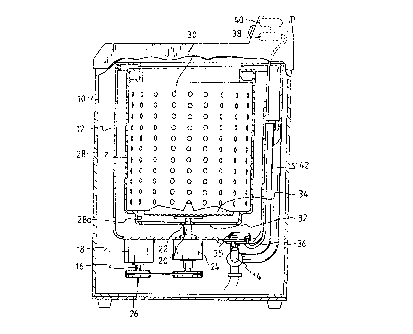
Referring now to Fig. 1, there is shown by way of
example a vortex-type washing machine in accordance with the
present invention. The washing machine comprises a housing 10 and
a stationary washer tub 12 fixedly mounted within the housing 10
for containing therein a level of washing fluid or detergent
CA 022~3008 1998-11-20
solution. Connected to the bottom of the stationary tub 12 is
a drain pipe that occasionally allows the washing fluid to flow
out of the stationary tub 12 during the washing, dewatering and
rinsing operations. The washing machine further includes an
electric motor 18 having a drive shaft 16 and a clutch assembly 24
having a first and a second driven shafts 20 and 22. As shown, the
electric motor 18 and the clutch assembly 24 are both secured to
the stationary tub by means of suitable fastener means, e.g.,
welding or threading. The drive shaft 16 is operatively connected
to the driven shafts 20 and 22 through a belt transmission
mechanism 26, for instance. The clutch assembly 24 serves to
selectively couple the driving force generated by the electric
motor 18 with one of the first and the second driven shafts 20
and 22.
lS The first driven shaft 20 carries at its top end a
rotatable washer tub 28 which is kept immovable during the process
of washing operation but is caused to rotate at a high speed during
the dewatering process. The rotatable tub! 28 is provided with, at
its side wall, a plurality of washing fluid communication holes 30
permitting the washing fluid to flow into or out of the rotatable
tub 28 and, at its bottom wall, a bubble passage 32 through which
~ air bubbles may penetrate into the rotatable tub 28, as further
set forth below.
Rotatably mounted on the bottom surface of the rotatable
tub 28 is a pulsator 34 carried by the second driven shaft 22.
The pulsator 34 is rotatable in a forward or reverse direction to
CA 022~3008 1998-11-20
.
-- 10 --
create a vortex flow within the rotatable tub 28, the structural
details of which will be discussed below with reference to Fig. 4.
A bubble generator 35 is located on the bottom surface
of the stationary tub 12 in order to generate a volume of air
bubbles which will in turn penetrate into the rotatable tub 28
through the bubble passage 32. The bubble generator 35
communicates th~ough an air conduit 36 with an air pump 38 which
serves to create a volume of pressurized air under a precise
control of a control device 40. An overflow pipe 42 is provided
outside the stationary tub 12 to gather and then bypass the
washing fluid and/or foams which may flow over the stationary
tub 12 in the course of washing or dewatering operation.
Turning to Fig. 2, there is shown in detail the
positional relationship of the bubble generator 35 with respect
to the rotatable tub 28 and the drain pipe 14. As shown, the
bubble generator 35 is positioned on the bottom surface of the
stationary tub 12 so as to emit or shoot the air bubbles toward
the bubble passage 32 of the rotatable tub 28. This will enable
the air bubbles to penetrate into the rotatable tub 28 with
little loss. Moreover, the location of the bubble generator 35
immediately above the drain pipe 14 facilitates movement of the
fluid contained in the bubble generator 35, during the draining
process, into the drain pipe 14.
Figs. 3A and 3B illustrate a preferred embodiment of
the bubble generator 35 which is applicable to the washing machine
of Fig. 1. This bubble generator 35 comprises a casing 48 ilaving
CA 022~3008 1998-11-20
-- 11 --
an inlet port 44 connectable to the air pump represented as 38
in Fig. 1 and an inclined outlet port 46 opposite the inlet port
44. Inserted within the casing 48 is a porous member 50 made of,
e.g., sponge. The porous member 50 provides an interface at which
the pressurized air from the air pump meets the washing fluid. The
pressurized air will be broken to a plethora of fine bubbles as it
passes through the porous member 50. A bubble orientation plate
52 having a number of through-holes 54 is rigidly attached to the
outlet port 46 at such an inclined angle that the air bubbles
created in the bubble generator 35 can be directed toward the bubble
passage 32 of the rotatable tub 28 as clearly shown in Fig. 2.
It is preferable that an elastic flap 56 of sufficient
flexibility be secured to the upper margin of the bubble orientation
plate 52. The elastic flap 56 normally assumes a first position
shown in a phantom line in Fig. 3A to close off the through-holes
54 of the bubble orientation plate 52. When the bubble ~enerator
35 begins to operate, the elastic flap 56 will flex to a second
position shown in a solid line in Fig. 3A, allowing the air bubbles
to be emitted from the bubble generator 35. Thus, the elastic flap
56 functions to prevent any foreign materials, released from the
laundry articles during the washing operation, from infiltrating
into the bubble generator 35 or clogging the through-holes 54,
which would otherwise lead to a premature failure of the bubble
generator 35. In addition, the casing 48 is provided with at its
bottom wall a drain port 58 that facilitates removal of the
residual fluid contained in the casing 48 whenever the washing
CA 022~3008 1998-11-20
fluid is drained through the drain pipe in the draining process.
The drain port 58 of the casing 48 terminates at its top slant
surface 58a which is configured to make the residual fluid flow
toward the drain port 58.
Referring to Fig. 4, there is shown a pulsator 34 which
may be advantageously employed in the present invention. The
pulsator 34 has a plurality of radial ribs or blades 60 for causing
a vortex flow within the rotatable tub~ 28. Each of the ribs ~0
is provided with an array of axial holes 62 pierced through the
thickness of the pulsator 34.
The axial holes 62 serve to pass a part of the air bubbles
to the upper space of the rotatable tub 28, especially when the
pulsator is in its cease period. Apart from the axial holes 62,
there is provided on the peripheral underside of the pulsator 34 a
multiplicity of equally spaced radial grooves 64 through which t~e
remaining part of the air bubbles rises up toward the upper space
of the rotatable tubi 28. As best shown in Fig. 5, the pulsator
34 of the above shape and configuration makes it possible to feed
the air bubbles into the rotatable tub 28 in a highly uniform
condition. Particularly, most of the air bubbles passing through
the radial grooves 64 come into collision with a bubble impinging
surface 28a and then travels upward in an inclined direction. This
maximizes the amount of air bubbles coming into contact with the
laundry articles contained in the rotatable tub 28.
It is of importance to note that the air bubbles in the
instant invention should be fed to the rotatable tub 28 in a
CA 022~3008 1998-11-20
- 13 -
batchwise manner, and not continuously, at such a time interval
that most of the previously supplied air bubbles are collapsed or
extinguished by themselves or under the influence of the vortex
flow. The time interval is controlled by means of a control device
which will be further described with reference to Figs. 8 to 13.
While a specific device for supplying air bubbles into the rotatable
tub has been disclosed hereinabove, the invention is not limited
thereto and many changes may be made without deteriorating the
bubble supply efficiency. For example, it may well be possible to
provide a bubble passage along the shaft of the pulsator 34.
As is apparent from Fig. 6, the present invention can
equally be applied to A drum-type washing machine. This type of
washing machine normally comprises a housing 66 and a stationary
tub~ 68 encased within the housing 66 for containing a level of
washing fluid. Horizontally mounted on the stationary tub. 68 is
a rotary drum 70 capable of accommodating laundry articles therein,
the lower portion of the rotary drum 70 being submerged under the
washing fluid. The rotary drum 70 has a multiplicity of through-
holes 74 which are distributed in a substantially uniform pattern
to allow the washing fluid to flow into or out of the drum.
As depicted in Fig. 7, the rotary drum 70 inclu~es four
axially extending notches 76 that are spaced apart from one another
along the circumference of the drum. Each of the axial notches 76
has a curved leading surface 78 and a flat trailing surface 80
substantially perpendicular to the leading surface 78. Formed on
the trailing surface 80 is an axial slot 82, the width of which is
CA 022~3008 1998-11-20
large enough to smoothly pass the air bubbles therethrough.
Turning back to Fig. 6, the bubble generator 86 is
positioned on the bottom of the stationary tub 68 and communicates
with an air pump(not shown) through a conduit 84. It should be
appreciated that the bubble generator 86 operates intermittently
to feed a predetermined amount of air bubbles into the rotary drum
in a periodic batchwise manner. The amount and the supply interval
of the air bubbles are controlled by means of a control device
which will be described below. Although the bubble generator shown
in Fig. 3 can also be applied to the drum-type washing machine with
r.o or little structural changes, other bubble generators may equally
be used for the bubble supply purpose. In order to maximize the
efficiency of air bubble infiltration into the rotary drum 70
through the axial slots 82 thereof, the bubble generator 86 is so
oriented as to emit or shoot the air bubbles toward the axial slots
82 in a counter-clockwise direction. This will prevent the air
bubbles shot by the bubble generator 86 from failing to penetrate
into the rotary drum and thereby flowing around the rotary drum at
the mercy of the clockwise liquid'stream.
Fig. 8 is a schematic diagram of a control device of a
preferred embodiment employing the invention. The control device
100 comprises a switch pad 91, detection means 92, a microprocessor
90, a load drive circuit 93 and an air pump drive circuit 94. As
shown in Fig. 8, the switch pad 91 and the detection means 92 are
connected to the inputs of the microprocessor 90 and the load drive
circuit 93 and the air pump drive circuit 94 are paired and
CA 022~3008 1998-11-20
connected to the outputs of the microprocessor 90.
The switch pad 91 includes a first switch station 91a
and a second switch station 91b wherein the first switch station
91a may have a plurality of type selection switches which are used
in advising the machine of the type of laundry articles to be
washed, and the second switch station 91b may also have a plurality
of level selection switches which enable the user to select a
preset volume of washing fluid in the washer tub 12 and 28 as
shown in Fig.1. For the convenience of manipulation, each type
selection switch in the first switch station 91a is provided with
an indicium representing the type of laundry articles, e.g., "wool"
or "cotton", and each level selection switch in the second switch
station 91b is provided with an indicium representing the volume
of washing fluid which may be devided by, e.g., three levels, i.e.,
"High", "Middle" and "Low". It is well known in the art that the
switch pad 91 may also comprise other switch station~, e.g., a
start switch station. When a type selection switch of the first
switch station 91a and a level selection switch of the second
switch station 91b are depressed by the user, a type signal
indicative of the type of laundry article~ and a level signal
indicative of the level of washing fluid are respectively issued
to the microprocessor 90.
The detection means 92 comprises a load sensor 92a for
detecting the weight of the specific type of laundry articles
contained within the washer tub 28 shown in Fig.l and a level
sensor 92b for sensing the volume of the washing fluid contained
CA 022~3008 l998-ll-20
- 16 -
therein. The load sensor 92a, as well known in the art, detects
the turning inertia of the washer tub~ 28 containing the laundry
articles and issues a load signal indicative of the weight of
laundry articles to the microprocessor 90. The level sensor 92b
may be employed to determine whether or not the volume of the
washing fluid provided to the washer tub through a feed valve
(not shown) is equal to the volume selected by the second switch
station 91b. For the control scheme, the detection means 92 may
also include a photo sensor such as the one disclosed in U.S.
Patent 4,372,134.
The microprocessor 90, as shown in Fig. 8, may be of any
type of microprocessor suitable for such control purpose, which
has a storage region therein or a separate memory device. The
storage region may contain a plurality of washing course programs
15 ~ stored in the form of instructions and data, as further described
below. Each washing course program may be selected by the type
and the level selection signal and the load signal from the load
sensor 92a. The microprocessor 90 may execute and process a series
of instructions and data in response to the selected washer control
course to provide control signals to a load drive circuit 93 and an
air pump drive circuit 94.
The load drive circuit 93 comprises a motor drive circuit
33a, a drain valve circuit 93b and a feed valve circuit 93c. The
motor drive circuit 93a is responsive to a motor control signal
~5 from the microprocessor 90 to enable the motor to rotate the
pulsator 34 and the washing tube 28 shown in Fig. 1. The drain
CA 022~3008 1998-11-20
valve circuit 93b is responsive to a drain valve control signal
to turn on or off the drain valve(not shown) for displacing the
washing fluid from the washer tub . The feed valve circuit 93c
is responsive to a feed valve control signal to turn on or off the
feed valve (not shown) for supplying a predetermined amount of
washing fluid to the washer tub 12 and 28.
The air pump drive circuit 94 is responsive to the
injection control signal from the microprocessor 90 to energize the
air pump 101. In Fig. 8B, a detailed circuit diagram of the air
pump drive circuit 94 is shown in association with the microprocessor
90. The details of the load drive circuit 93, the switch pad 91
and the detection means 92 are omitted here for the sake of
convenience.
In Fig. 8B, the air pump drive circuit 94 comprises an
output control device 102 which is responsive to an output control
signal from the microprocessor 90 to control the output power of
the air pump 101; a triac TA1 which is adapted to connect the AC
source 103 to the air pump 101 via the output control device 102;
and a triac drive circuit 104 which is responsive to a triac
control signal from the microprossor 90 to turn on or off the
triac TA1. The triac drive circuit 104 comprises a transistor TR1
wherein the emitter of the transistor TR1 is connected to the gate
of the triac TA1, its collector is connected through a resistor R2
to the earth, and its base is coupled with an output port P1 of
the microprocessor 90. The base of the transistor TR1 is also
linked to the DC source Vcc via a resistor Rl. Referring to Fig.
CA 022~3008 1998-11-20
.
- 18 -
8B, it may be readily understood by one skilled in the art that,
with a constant output power of the air pump 101, the air pump
drive may be controlled by providing a "High" level or "Low" level
signal to the triac drive circuit 104 by turning on or off the
triac TA1 to link or separate the AC power source 103 to or from
the airpump 101.
Referring back to Fig. 8A, the control scheme of the
washer is performed by the control circuit 100, which comprises a
plurality of washing courses, each of which may be, as known in the
art, selected based on the type and the welght of laundry articles
and the volume of washing fluid; and involves three types of
operating modes, i.e., washing mode, rinsing mode, and dewatering
mode. That is, a given washing course may comprise: a washing
mode having a predetermined time period; a rinsing mode having a
preset number of operations; and a dewatering mode also having a
preset number of operations. The rinsing mode and the dewatering
mode may be alternately operable, and the predetermined time
period and the preset number of operations may be selected for
each specific washing course.
In the washing mode, when the washing fluid in the washer
tub~ reaches a predetermined level, forward and reverse motor drive
signals from the microprocessor 90 are sequentially sent to the
motor drive circuit 93a. The motor(18 a~ shown in Fig.l) is
alternately energi~ed by the ~otor drive circuit 93a to cause
forward and reverse rotation of the pulsator 34, thus producing a
water stream flowing in alternately opposite directions. The
CA 022~3008 1998-11-20
-- 19 --
forward and reverse rotation of the pulsator 34 can be made, e.g.,
on succesive time intervals of 2 equal seconds. As the pulsator
34 is rotated, the detergent is dissolved in washing fluid and
stains are removed from the laundry articles. In this manner, a
washing mode is initiated and proceeded for a predetermined time
period.
When the washing mode is completed, the output of the
motor drive circuit 93a is interrupted, and a drain signal from the
microprocessor 90 is given to the drain valve circuit 93b to open
the drain valve so that the washing fluid is removed from the
washer tub~. The motor is rotated only in one direction while this
dewatering mode of operation continues.
After the dewatering mode is ended, a rinsing mode with
an influx of fresh water is performed. The rinsing mode is similar
to the washing mode with the exception of the time interval of the
operation and the fresh water fed into the washer tub.. In a given
washing course, the rinsing mode and the dewatering mode may be
alternately performed for a predetermined number of times. As
known in the art, such combined modes of operations for a specific
washing course may be preprogrammed in the storage region of the
microprocessor 90.
According to the present invention, for the wa~hing
mode in a gi~en washing course, predetermined amounts of air bubbles
may be intermittently provided to the washer tub through tl:e air
2 p~lmp ~01 under the control of the microprocessor 90. Tnis is
achieved by alternately providing an 'njection control signal for
CA 022~3008 1998-11-20
- 20 -
an injection time period and a collapsing control signal for a
collapsing time period to the airpump drive circuit so as to
energize and deenergize the air pump 101 during the injection
and the collapsing time periods. Referring back to Fig. 8B, the
injection control signal may be, e.g., a "H" level voltage signal,
while the collapsing control signal may be a "L" level voltage
signal.
As described below, supposing that the output power of
the air pump 101 is fixed, the injection time period is determined
so as to correspond to the predetermined amount of air bubbles
which may be empirically obtained. Similarly, the collapsing
time period, during which the entire amount of air bubbles
introduced is substantially collapsed, may be experimentally
determined, which is normally equal to or greater than the
injection time period.
The predetermined amount of air bubbles is equivalent
to "the saturation bubble quantity" which is the maximum amount
of air bubbles that may be kept, under tlie normal operating
conditions, i.e., the amount of air bubbles before they begin to
2~ overflow, within the washer tub 28 containing a given load of
laundry articles and a given level of washing fluid.
The present inventors have empirically discovered that
the saturation bubble quantity yt may be rel)resented by the
following formula:
Y~ a x ......................... (Eq. 1)
CA 022~3008 1998-11-20
wherein x is the weight of laundry articles, ~ denotes a reference
bubble quantity and ~ represents a coefficient of the bubble
supply.
The reference bubble quantity ~ is a constant value
corresponding to a given volume of washing fluid, which has been
empirically found to approximately statisfy:
~ = V x 1/10 ............................... (Eq. 2)
wherein V is the volume of washing fluid contained in the washer
tub .
The bubble supply coefficient ~ is also experimentally
found to be within the range from 0.55Q ikg to 0.68Q /kg. The
capacity of the washing machine is generally represented by the
maximum weight of laundry articles which may be accommodated
within the washer tub , whereas the maximum volume of washing fluid
for the respective capacity of the washing machine is confined by
the size of the washer tub thereof. Experimentally, the bubble
supply coefficient ~ may be determined to be, e.g., 0.596Q ~kg
for a 5.2kg washing machine, 0.666Q /kg for a 6.6kg washing machine
and 0.623Q /kg for a 7.5kg washing machine, respectively.
Fig. 9 depicts a graphical representation illustrating
a relationshp betweell the quantity of air bubbles, y, and the
weight of laundry articles, x, with the volume of washing fluid
as a parameter(A, B and C) whereill Wl(e.g., 2.5~ 5.2kg), W2(e.g.,
3.5~ 6.6kg) and W3(e.g., 4~ 7.5kg) represent the working load
CA 022~3008 1998-11-20
range of laundry articles which can be preferably contained in,
e.g., the respective 5.2kg, 6.6kg and 7.5kg washing machines with
the respective volume of washing fluid A(e.g., 54Q ), B(e.g., 69Q )
and C(e.g., 78Q ). As shown in Fig. g, for a given volume of
washing fluid A, B or C, the saturated bubble quantity which is
represented by the dots is negatively proportional to the weight
of laundry articles, which can be closely approximated by Eq. 1
for the working load range of laundry articles in a given washing
machine.
Now, assuming the volume of washing fluid is 54Q and
the weight of laundry articles is 5.2kg, the saturated bubble
quantity is y~ = 54 x 1/lO(Q ) - 0.596Q /kg x 5.2kg = 2.3Q .
As mentioned previously, the injection time period may be
computed based on the saturated bubble quantity obtained for a
given air pump having a constant output power. That is, assuming
the output power of the air pump is 38.3cc/sec, the injection time
period is 2.3Q . 38.3cc/sec ~. 60sec and the collapsing time
period may be determined either empirically or by selecting a
period identical to or slightly greater than the injection time
period as described above.
Consequently, the injection and the collapsing time
periods may vary with a given washing course which is selected based
on the weight of laundry articles and the volume of was~ing fluid.
It should also be understood that th2 injection and the collapsing
~5 time periods for a selected washing course may be computed using a
computer program of the microprocessor employing Eq. 1; or a set
CA 022~3008 1998-11-20
- 23 -
of data for the injection and the collapsing time periods compiled
empirically may also be stored in the storage region of the
microprocessor.
Table 1 summarizes exemplary data on the injection and
the collapsing time periods, which are empirically obtained by way
of conducting a washing mode operation comprising 6 cycles in
three separate washing courses under the optimal condition using
a 5.2kg capactiy washing machine.
Table 1
(unit: sec)
Washing Injection and Collapsing Time Periods
Course d c d c d c d c d c d c
1 70 70 50 50 60 60 60 60 60 60 60 60
2 50 70 50 70 50 70 50 70 50 70 50 70
3 40 40 20 20 30 30 30 30 30 30 30 30
(output power of the air pump: 38.3 cc/sec)
d: injection time period c: collapsing time period
In carrying out the first washing course to generate the
data listed in Table 1, 5.2kg of laundry articles is washed with
54Q of washing fluid. Similarly, the second and the third washing
courses are conducted with 3kg and 1.5~:g laundry articles in 37Q
and 20Q of w~shina fluid, respectively.
~y repeating and coverina various possible operation
CA 022~3008 1998-11-20
- 24 -
conditions, therefore, data bank for the injection and the
collapsing time periods as a function of,the weight of laundry
articles and the volume of washing fluid is generated and can be
stored in the memory region of the control circuit and accessed
when an appropriate washing course is selected by the ~witch pad
91 and the detection means 92.
Fig. 10 is shown a flow chart of the air pump control
performed by the microprocessor 90 depicted in Fig. 8. In step
105, when the switch pad 91 is depressed by the user and the
weight of laundry articles is detected by the load sensor 92a, a
type selection signal indicative of the type of laundry articles,
a level selection signal indicative of the volume of washing fluid
from the switch pad 91 and a load detection signal indicative of
the weight of laundry articles from the load sensor 92a are applied
to the microprocessor 90.
In step 106, the microprocessor 90, in response to the
type selection signal, the level selection signal and the load
detection signal, determines a specific washing course.
In step 107, the microprocessor 90 also determines a
series of the injection and the collapsing time periods for the
specific washing course.
In step 108, the microproccessor 90 alternately provides
the air pump driYe circuit 94 with the injection control signal
for the in~jection time period and the collal~sin~ control signal
for the collapsing time period durin~, the washing mode of operation
preset in a specific washing course; and similarly provides the
CA 022~3008 1998-11-20
- 25 -
injection and the collapsing control signals to the air pump dri-~e
circuit 94 during the rinsing mode of operation thereof.
Description will now be given by way of the following
examples to further illustrate the preferred features and
advantages of the present inYention.
Example 1
Initially, 5.2kg of dirty cotton towels together with
104g of a detergent formula were put into the washing tub of the
improved washing machine of the present invention, containing
therein 54Q of water heated to abol~t 30~C. The detergent was
comprised of 20.8g of lauric acid, 5.2g of sodium carbonate, 52g
of sodium sulfide and 26g of sodium tripolyphosphate. While the
pulsator was in its normal operation, the air pump was energized
for 60 seconds to feed 2.3Q of air bubbles into the washing tub
and then deenergized for another 60 seconds to allow the air bubbles
to be collapsed virtually in their entirety. Such energizing/
deenergizing cycle of the air pump was repeatedly carried out for
a time period of 16 minutes; and the degree of detergency, D, was
measured at a time interval of 2 minutes and plotted to obtain
curYe A1 as shown in Fig. 11. The degree of detergency, D, was
calculated as follows:
2~ Rw - Rl
D = ~ 100(%)
~O - Rl
CA 022~3008 1998-11-20
- 26 -
wherein Ro is th~: reflective index of a clean reference towel, R
represents the pre-washing reflective index of a dirty towel and
R~ denotes the post-washing reflective index of the cleaned towel.
As is apparent from Fig. 11, the present washing machine
has the ability to wash the soiled laundry articles, to a higher
degree of detergency(9OZ) within a relatively short period of time
(16 minutes).
Exam~le 2
The same operation as in Example 1 above was carried
out without any air bubbles fed into the washing tub~. During
the course of washing operation, the degree of detergency was
measured at a time interval of 2 minutes and plotted to obtain
curve A2 as illustrated in Fig. 11. The degree of detergency
reached around 78% after 16 minutes of washing
Exa~Dle 3
The same operation as in Example 1 above was carried
out except that the air bubbles were fed into the washing tub~
continuously. As in the previous experiments, the degree of
detergency was measured at a time interval of 2 minutes and
plotted to obtain curve A3 as shown in ~ig. ll. The degree of
detergency measured at the end of washino, operation was around
51%.
CA 022~3008 1998-11-20
- 27 -
The above comparative results clearly demonstrate the
superior performance of the improved washing machine of the present
invention in terms of its washing efficiency in a reduced period of
washing time.
Furthermore, the present invention may equally be applied
to the rinsing mode, in addition to the normal washing mode set
forth hereinabove. For example, a single batch of air bubbles can
be supplied to the washing tub immediately before the pulsator
begins to operate in the rinsing mode. As the rinsing operation
proceeds, the air bubbles tend to remove the odor source, i.e.,
the residual detergent left in the washed articles, consequently
providing an unexpected deodorization effect. As a result, the
level of odor lingering in the laundered articles is reduced to
such an extent that the user can hardly sense it.
While the best mode and preferred embodi~ents of the
invention have been described herein, variations and changes may
be made without departing from the scope and spirit of the
invention.